ELCOM TLM 1500 ITS 24V Operating instructions

Modular transfer system
24 Volts
ITS - TLM 1500
User & maintenance manual
I02-243 / Translation of the original manual, version 03

I02-243 User & maintenance manual Version 03 (translation of the original manual)
of TLM1500 ITS 24 V
Version tracking:
Version
Date
Description of modifications
Prepared by
Approved by
00
07/08/17
Initial
O. CELARD
M. MALEO
01
14/09/17
Modification of security instructions
O. CELARD
M. MALEO
02
23/01/18
Precision on motor wiring
O. CELARD
M. MALEO
03
18/09/18
Added information for disassembly
and wiring of CROUZET drive motors +
2015 edition of ISO 9001 and 14001
standards: deletion of expired
certificates
O. CELARD
S. MAIRET
M. MALEO

I02-243 User & maintenance manual Version 03 (translation of the original manual)
of TLM1500 ITS 24 V
Table of contents
1 General information.........................................................................................................................1
1.1 Important notice ..................................................................................................................... 1
1.2 Applicable standards............................................................................................................... 1
1.3 Applications ............................................................................................................................ 1
1.4 Terms of use............................................................................................................................ 1
1.5 Security instructions................................................................................................................ 2
1.6 Motor’s safety instructions ..................................................................................................... 2
1.7 Additional information............................................................................................................ 3
2 Technical caracteristics ....................................................................................................................3
3 Commisionning.................................................................................................................................4
3.1 Receipt of equipment.............................................................................................................. 4
3.2 Stopper.................................................................................................................................... 4
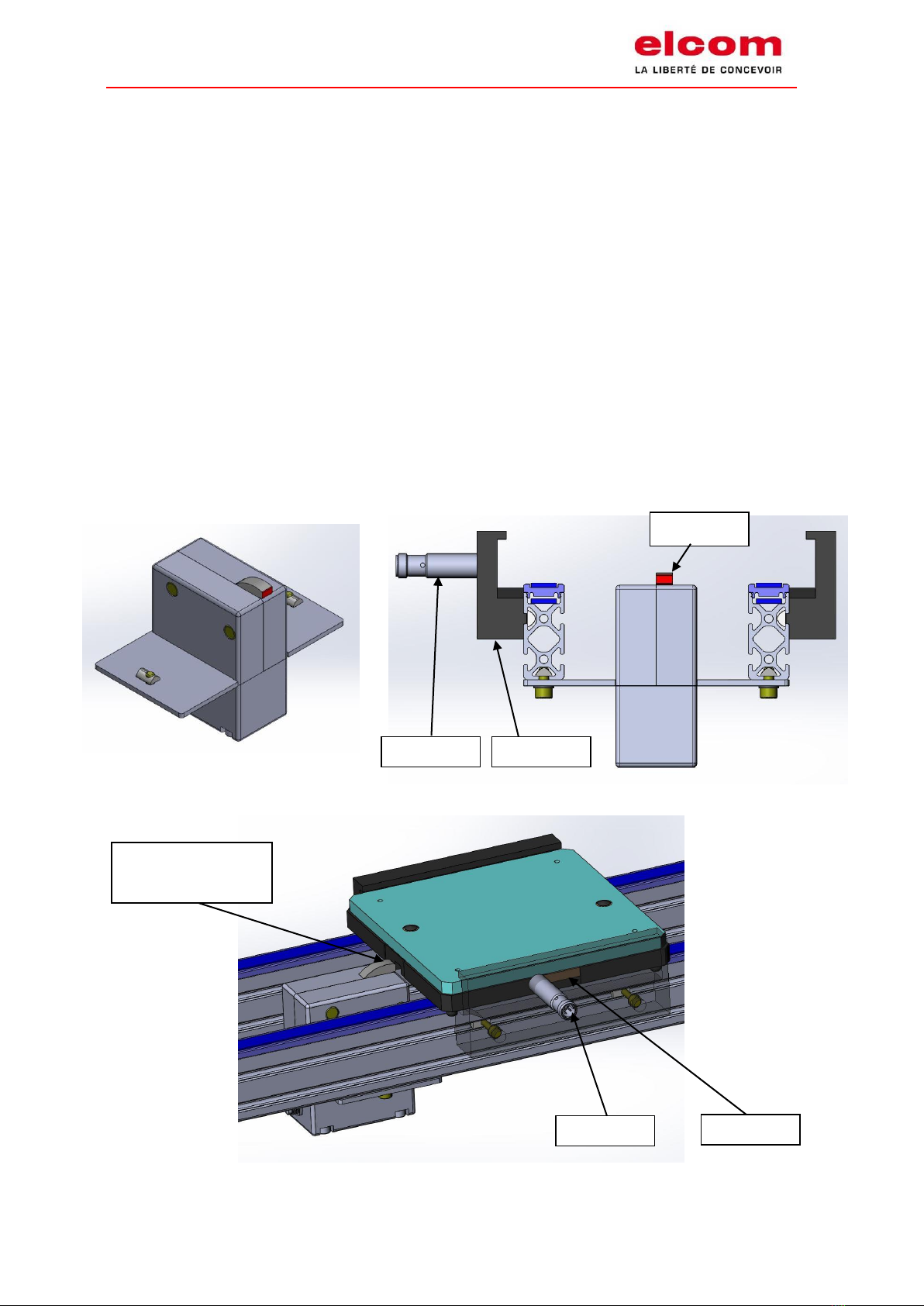
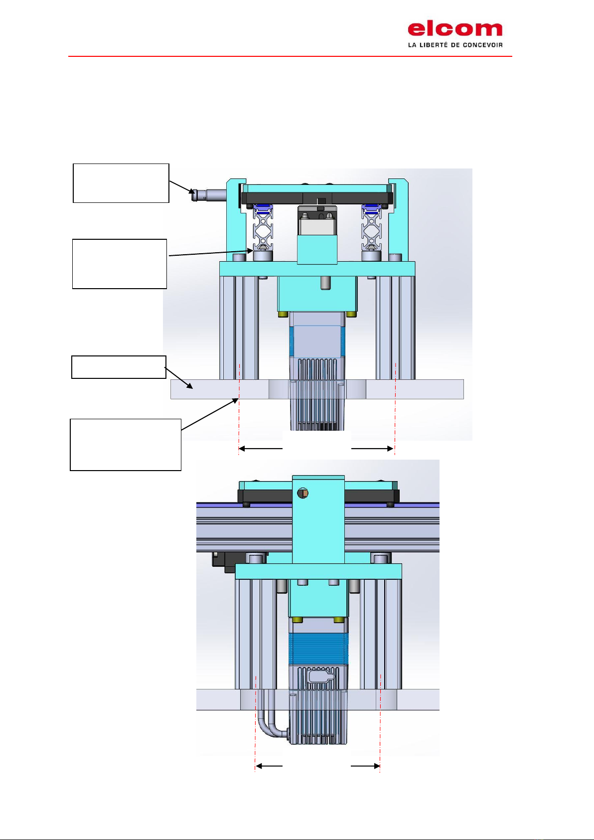
3.3 Positioning unit........................................................................................................................ 5
3.4 Double cam.............................................................................................................................. 6
3.5 Derivation................................................................................................................................ 7
3.6 Carrier...................................................................................................................................... 8
4 Maintenance ....................................................................................................................................9
4.1 Belts wear................................................................................................................................ 9
4.2 Passageways of workpiece carriers......................................................................................... 9
4.3 Pins .......................................................................................................................................... 9
4.4 Wear of the belt guide ............................................................................................................ 9
4.5 Transfert parts....................................................................................................................... 10
4.6 Stoppers ................................................................................................................................ 10
4.7 Positioning unit...................................................................................................................... 11
4.8 Double cam............................................................................................................................ 12
4.9 Derivation.............................................................................................................................. 12
4.10 Other elements of the transfert............................................................................................ 12
5 Changeout of the 24V drive motor ............................................................................................... 13
5.1 Unit with PAPST drive motor:................................................................................................ 13
5.2 Unit with CROUZET motor drive :.......................................................................................... 16
6 Changeout of the drive motor of index unit 24v........................................................................... 19
7 Changeout the toothed belt.......................................................................................................... 21
8 wiring the 24v drives motors......................................................................................................... 22
8.1 Unit with PAPST drive motor :............................................................................................... 22
8.2 Unité avec moteur CROUZET :............................................................................................... 23

I02-243 User & maintenance manual Version 03 (translation of the original manual)
of TLM1500 ITS 24 V
9 Wiring of the drive motor of index unit 24v.................................................................................. 24
10 wiring of the 24v stoppers............................................................................................................. 27
10.1 Connectic required to wire the electrical stoppers (see schematic simple card for stopper).... 27
10.2 Wiring of the control box of the stoppers............................................................................. 29
10.3 Connectic required to wire the doubles cams and derivations ............................................ 31
10.4 Wiring of the control box of the double cam 24V or derivation 24V.................................... 33
11 Responsability ............................................................................................................................... 35
12 CUSTOMER SERVICE...................................................................................................................... 35
13 Appendix........................................................................................................................................ 36
13.1 Maintenance schedule .......................................................................................................... 36
13.2 Quality and environmental commitment: ISO certifications ................................................ 37

I02-243 User & maintenance manual Version 03 (translation of the original manual)
of TLM1500 ITS 24 V Page 1of 37
1GENERAL INFORMATION
1.1 Important notice
The following instructions are used as technical documentation for the manufacturer of the final
machine system. elcom company is the provider of the subset transfer system TLM 1500 ITS 24V.
The manufacturer of the final machine system must ensure that all safety equipment is provided and
functional, that regular checks are made, that any danger arising from moving parts is controlled or
reported (pinch, shear) and that the documentation is complete.
1.2 Applicable standards
The machine system where the subset is incorporated cannot be in service until all the terms and
conditions established by directive 2006/42/CE have not been applied.
According to the European Directive 2006/42/CE, elcom transfer systems are considered as almost
full machine system. They are therefore not subject to an EC declaration of conformity but are the
subject of a declaration of incorporation. The latter is transmitted at the time of delivery,
accompanied by the exploded view of the motorized equipment.
However, the following standards are considered for the design of elcom transfers:
×2006/42/CE directive related to machine systems
×73/23/CE directive related to electrical equipment
Elcom company provides monitoring and quality recognized by the ISO 9001 certification.
Regarding the environment respect, elcom company is also ISO 14001 certified.
1.3 Applications
The linear transfer elements TLM1500 ITS24V are provided for moving and positioning workpiece
carriers depending on each configuration for the end customer.
They are intended to be incorporated in all the line of the user.
1.4 Terms of use
The elements of the TLM 1500 ITS24V transfer system is provided for a normal use in industrial
workshop, type assembly or equivalent, in a dry environment.
They are not suitable for the transport of materials such as sand, granules or grains.
The maximum load applicable to the transfer system is specified in the catalog and must always be
strictly followed.
To ensure a proper operation of the transfer and an optimal lifetime, using shall be focused on the
followings :
×Operating temperatures between 0° and 40° C,
×Avoid dusty or smoky atmospheres,
×Avoid accumulation of sharp edged objects on conveyor,
×Avoid positioning of the machine under direct exposure to UV rays.

I02-243 User & maintenance manual Version 03 (translation of the original manual)
of TLM1500 ITS 24 V Page 2of 36
1.5 Security instructions
The security rules regarding transfer system, especially those related to electrical
equipment must be followed during all using states: installation, transportation,
production. To not follow these rules would be considered as bad use of the device.
Use the transfer in an explosive area may affect the integrity of the conveyor and is
strongly not recommended.
Never handle maintenance operation alone: another person must be compulsory present
in order to turn off power and apply first aid if necessary.
During any handling on the moving transfer or nearby (use, tension setting of the belt …),
do not slide your hand between the belt is the support to prevent from any accident.
During the manipulation or using of the working transfer line, be careful of pinching
areas indicated by this pictogram.
1.6 Motor’s safety instructions
In the case of a power failure, the motor relay must fall, restarting the engines will be
gradual and cycled with the restart of the plant. The engines are not suddenly restart
when power is restored to the installation.
In contrary to the three-phase motors, 24V motors can be stopped frequently. During an emergency
stop, you should stop the transport units in the area.
When you restart, it is necessary to delay a few seconds the start-up of the motors, in order to
ensure the proper functioning of the stoppers (and positioning units), before to moving the
workpiece carrier on the transfer
No reset by the controller is not necessary for the stoppers and positioning units, repositioning is
done automatically (integrated program component).

I02-243 User & maintenance manual Version 03 (translation of the original manual)
of TLM1500 ITS 24 V Page 3of 37
1.7 Additional information
The aim of these instructions is to guarantee people safety and proper use of the transfer system. If
you wish to use the transfer system in any other conditions, don’t hesitate to contact us.
More information is available on elcom website:
http://elcom-automation.com/transfers/documentation
2TECHNICAL CARACTERISTICS
- Maximum weight on workpiece carrier : 4 kg (except workpiece carrier)
- Maximum weight accumulation on stopper : 35 kg for a maximum stretch of 3 meters.
- Electric tension alimentation for motors: Direct 24 V
- Power consumption by motors : C = 0 (no load) →P < 10W
(C= load in kilograms) C = 35Kg →20W < P < 50W
Installed power for this equipment : 220 V - 150 W
- Emission sonore : < 80 dB
- Module weight : See the catalog « Transfert linéaire modulaire & convoyeurs à bandes ».
http://elcom-automation.com/transfers/documentation
Warning ! Every overload can lead to advanced damage for the belt or any other
element.

I02-243 User & maintenance manual Version 03 (translation of the original manual)
of TLM1500 ITS 24 V Page 4of 37
3COMMISIONNING
3.1 Receipt of equipment
When receiving the material, check that the packaging has not been damaged and that the
equipment is in perfect condition.
3.2 Stopper
1. Place the stopper right in the middle of the two profiles of the system.
2. Put the workpiece carrier in contact of the stopper.
3. Adjust the presence detection range :
-Move the 2 claws to align the sensor with the cam of the workpiece carrier (the sensor
must pass 1)
-When the sensor returns to 0, the stop back into the groove of the workpiece carrier.
Sensor
Claw
Cam
Work piece carrier
against the stopper
Sensor
Stopper

I02-243 User & maintenance manual Version 03 (translation of the original manual)
of TLM1500 ITS 24 V Page 5of 37
3.3 Positioning unit
1. Place the stopper right in the middle of the two profiles of the system.
2. The presence detection range is preset.
3. The positioning unit has to be fixed on a frame and not under the transfer.
4. Fix the transfer on the positioning unit.
Machine frame
Presence
detector range
Transfer fixed on
the positioning
unit
120mm
160mm
Screw mounting
4 x M8

I02-243 User & maintenance manual Version 03 (translation of the original manual)
of TLM1500 ITS 24 V Page 6of 37
3.4 Double cam
See overall drawing and assembly N°: 150 21 000 E

I02-243 User & maintenance manual Version 03 (translation of the original manual)
of TLM1500 ITS 24 V Page 7of 37
3.5 Derivation
See overall drawing and assembly N°: 150 07 000 E (Right version) et 150 13 000 E (Left version)

I02-243 User & maintenance manual Version 03 (translation of the original manual)
of TLM1500 ITS 24 V Page 8of 37
3.6 Carrier
1. Check the function of the springs and the pins under the workpiece carrier.
2. Check that no part goes over the lower surface of the workpiece carrier.
4 Pins
Stopper
groove

I02-243 User & maintenance manual Version 03 (translation of the original manual)
of TLM1500 ITS 24 V Page 9of 37
4MAINTENANCE
General visual check
Approximately every 500 hours, check the following points to ensure the proper functioning of the
transfer system.
4.1 Belts wear
Regularly verify visually the state of the belt and especially the welding area
4.2 Passageways of workpiece carriers
The friction of the pins while operating can make some marks appear. Those marks may over the
long term require the part replacement.
4.3 Pins
Pins are sensitive to wear, especially if the load is heavy. Wear can be noticed as soon as a loss of
efficiency in the guiding of the workpiece carrier.
4.4 Wear of the belt guide
Belt guide must be replaced as soon as wear marks or friction on the belt start to appear.
Wear area of the pins
Belt
Belt guide

I02-243 User & maintenance manual Version 03 (translation of the original manual)
of TLM1500 ITS 24 V Page 10 of 37
4.5 Transfert parts
Every 200 hours :
Remove dust from the whole system.
Use the product, réf. 800 00 003 (polish plastique Air Industry 2101).
4.6 Stoppers
Every 5 000 hours :
Clean all stoppers.

I02-243 User & maintenance manual Version 03 (translation of the original manual)
of TLM1500 ITS 24 V Page 11 of 37
4.7 Positioning unit
Every 1,000 hours:
Clean and lubricate guiding shafts :
•Take off the stopper Rep 3 by unscrewing 2 CHC M4 Rep 4.
•Take off the index plate Rep 1 by unscrewing the CHC M4 Rep 2.
•Clean and lubricate the guiding shafts Rep 5 (grease reference : 800 00 002)
Tool needed, Hex keys
•To reassemble, please follow the instructions in the other ways.
1
2
3
4
5

I02-243 User & maintenance manual Version 03 (translation of the original manual)
of TLM1500 ITS 24 V Page 12 of 37
4.8 Double cam
Every 5,000 hours :
Clean all double cams.
4.9 Derivation
Every 5,000 hours :
Clean all derivations.
4.10 Other elements of the transfert
Other elements do not require a specific maintenance.
A regular visual control is advised to check if there is no broken components and to control wear
parts.

I02-243 User & maintenance manual Version 03 (translation of the original manual)
of TLM1500 ITS 24 V Page 13 of 37
5CHANGEOUT OF THE 24V DRIVE MOTOR
Shut down the machine that integrate the transfer system.
Disconnect the wires of the drive to replace.
5.1 Unit with PAPST drive motor:
Take off the drive motor support Rep 8, fixed by 4 screws CHC M5 Rep 9 (see picture below)
Tool needed, Hex keys
Take off belt Rep 7
13
14
9
8
7

I02-243 User & maintenance manual Version 03 (translation of the original manual)
of TLM1500 ITS 24 V Page 14 of 37
Take of the part Rep 8 fixed by 4 screws CHC M5 Rep 10.
Note : Please be sure to note the orientation of this part on the drive, in order to put the new drive in
the correct position.
Take off the sprocket Rep 5 fixed by the pressure screw M4 Rep 6, and take off the spacer Rep 11
8
10
5
6
11

I02-243 User & maintenance manual Version 03 (translation of the original manual)
of TLM1500 ITS 24 V Page 15 of 37
Mouting of the new drive motor :
Do all operation in the other way in order to mount the new drive motor.
Note : in order to ease the positonning of the new drive motor, loosen the belt Rep 7 at the
maximum and present the drive motor with an angle with regard to the support part
Drive motor documentation :
http://img.ebmpapst.com/products/datasheets/VDC34915K4B00-1454904.pdf
7
Drive motor refrence : 150 50 251

I02-243 User & maintenance manual Version 03 (translation of the original manual)
of TLM1500 ITS 24 V Page 16 of 37
5.2 Unit with CROUZET motor drive :
Take off the drive motor support Rep 8, fixed by 4 screws CHC M5 Rep 9 (see picture below) and the
hood Rep 13, fixed by 4 screws CHC M4 Rep 14.
Tool needed, Hex keys
Take off belt Rep 7
13
14
9
7
8
Table of contents
Other ELCOM Accessories manuals