Westgate SOLF-17W-50K User manual

SOLF
LED Solar Light
Instruction Sheet
Please read the following EXTREMELY IMPORTANT
information BEFORE INSTALLATION to ensure your
satisfaction.
READ BEFOREREAD BEFORE
INSTALLATIONINSTALLATION

Read this Instruction manual carefully to ensure proper installation. Please keep this instruction manual for future use.
MUST KNOW ABOUT THIS FIXTURE:
• This solar xture is equipped with a dusk to dawn sensor only to turn on when darkness is detected.
• The xture is designed to stay on with dimmed brightness all night and switch to full brightness when
motion is detected. The xture isn’t intended to stay on 100% brightness continuously.
• The average direct sunshine exposure in the installation area should be at MINIMUM 3.5h/day to ensure
the full functionality of the lighting xture.
• The working temperature of the solar xture is - 4 F to 104 F. But the Battery will stop charging at below
32 F.
• Battery power is less than 40%; the brightness will automatically be reduced by 50% .
• The indicator blinks green slowly when there is less than 10% battery power. When the charge is less than
5%, the xture will shut down.
• The Battery drains every four months when not charged adequately by sunlight or electricity.
MUST DO BEFORE INSTALLATION:
1. Before installation, please check the battery to see if it’s fully charged. Please proceed to theinstallation on
sunny days. Please see the indicator color guide on page 3
2. Before installation, please press the ON/OFF key in the remote control and check whether the
redindicator blinks on the sensor. Please cover the panel and check if the indicator module turns
on,generally within 1 minute. If the light is still o, try the ON/OFF key on the remote one more time. Ifthe
indicator doesn’t blink red upon restart, contact the manufacturer.
3. (Before installation) Select the necessary operation mode with the remote control. Please refer
tothe instruction manual for the remote control for further information. Note: the xture is best set
at20%constant brightness with lumen increase when motion is detected. See the remote controlsettings
on page 2.
4. Before installation, please ensure the light pole foundation is solid enough to withstand the lightingxture.
5. Optimize the lighting xture positioning to optimize its exposition to sunshine. Always face theequator.
(Solar panel to face south if in the northern hemisphere, for example)
6. To allow self-cleaning, please have a minimum angle of 15 degrees.
7. Adjust the lighting xture angle to optimize its exposition to sunshine and the LED module angletoward
the area too bright up.
8. 8.Use the dedicated tool to disassemble the anti-theft screws. Note Dedicated tool not included orsold
separately.
9. Please select the correct operating mode according to the local legislation needs and sunshineconditions.
See the solar radiation map on page 4.
1Phone: (877) 805-2252 | Fax: (877) 805-2252
www.westgatemfg.com |
SOLF VOLTAGE WATTAGE COLOR TEMP. DIMMING
SOLF-17W-50K
120-277V AC
17W
5000K Use the remote control
to adjust
SOLF-36W-50K 36W
SOLF-54W-50K 54W
WARNING
Installation Instructions
OUTDOOR LIGHT

1. ON/OFF: when ON/OFF is pressed, the indicator blinks red if the xture is fully charged and ready to work. The indicator blinks green if
the battery power is less than 10%. If the indicator doesn’t blink upon restart, contact the manufacturer.
2. Test: To sync the remote control with the lighting xture, press hold for 3 seconds, then release this button. To test, press it once. If the
test is successful, the xture will light up to full brightness, dim down, and prepare for the next steps. If the test is unsuccessful, the
xture is either out of charge or turned off. Testing time lasts 10 seconds, and then it goes back to the previous mode in use.
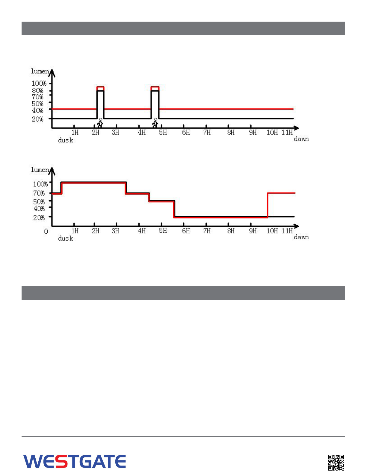
3. Induction Mode 40% - 100%: Constant 40% brightness (turn on at dusk, turn off at dawn); the light goes on 100% brightness for 30
seconds when motion is detected
4. Induction Mode 20% - 80% (Default): Constant 20% brightness (turn on at dusk, turn off at dawn); the light goes on 80% brightness for 30
seconds when motion is detected
5. Gradual Dim Mode: Based on night-time activities: 70% brightness for Hour 0 (Dusk)-0.5, 100% brightness for Hours 0.5-3.5, 70%
brightness for Hour 3.5-4.5, 50% brightness for Hour 4.5-5.5, 20% brightness for Hours 5.5-11 (Dawn).
6. Gradual Dim Mode: Based on night-time activities with increased brightness for early risers: 70% brightness for Hour 0 (Dusk)-0.5,
100%brightness for Hours 0.5-3.5, 70% brightness for Hour 3.5-4.5, 50% brightness for Hour 4.5-5.5, 20% brightness for Hours 5.5-10,
70% brightness for Hour 10-11 (Dawn).
7. Constant Mode 100%: 100% brightness from dusk to dawn. Suitable for areas and seasons with sufcient sunlight.
8. Constant Mode 70%: 70% brightness from dusk to dawn. Suitable for areas and seasons with sufcient sunlight.
9. Constant Mode 40%: 40% brightness from dusk to dawn. Suitable for areas and seasons with sufcient sunlight.
10. Timer Disabled: Press this button to turn off Timer Mode; Settings go back to the previous mode that was set before timer mode.
11. Timer Mode 4 Hours: Light turns off 4 hours after it turns on (dusk). For example: Press this button at any time; if the light turns on at
7pm, it will turn off at 11 pm. It will repeat the same schedule hereafter until it is canceled by using 10 Timer Disabled.
12. Timer Mode 8 Hours: 8 Hours Light turns off 8 hours after turning on (dusk). For example: Press this button at any time; if the light turns
on at 7 pm, it will turn off at 3 am. It will repeat the same schedule hereafter until it is canceled by using 10 Timer Disabled.
2Phone: (877) 805-2252 | Fax: (877) 805-2252
www.westgatemfg.com |
Function:
1. ON/OFF 2. Test
3. Induction Mode 4. Induction Mode
(Default)
5. Gradual Dim Mode 6. Gradual Dim Mode
7. Constant Mode 8. Constant Mode
9. Constant Mode 10. Timer Mode Disabled
11. Timer Mode 12. Timer Mode
• The range of the remote control to the indicator is 16ft (Day time) to 33ft (Nighttime). Because the sunlight will impact the signal of the remote
control, we recommend that users set up the mode before they install the light.
Introduction of Remote Control button
Note: Remote control not included MUST BE PURCHASED separately-1 Per Project
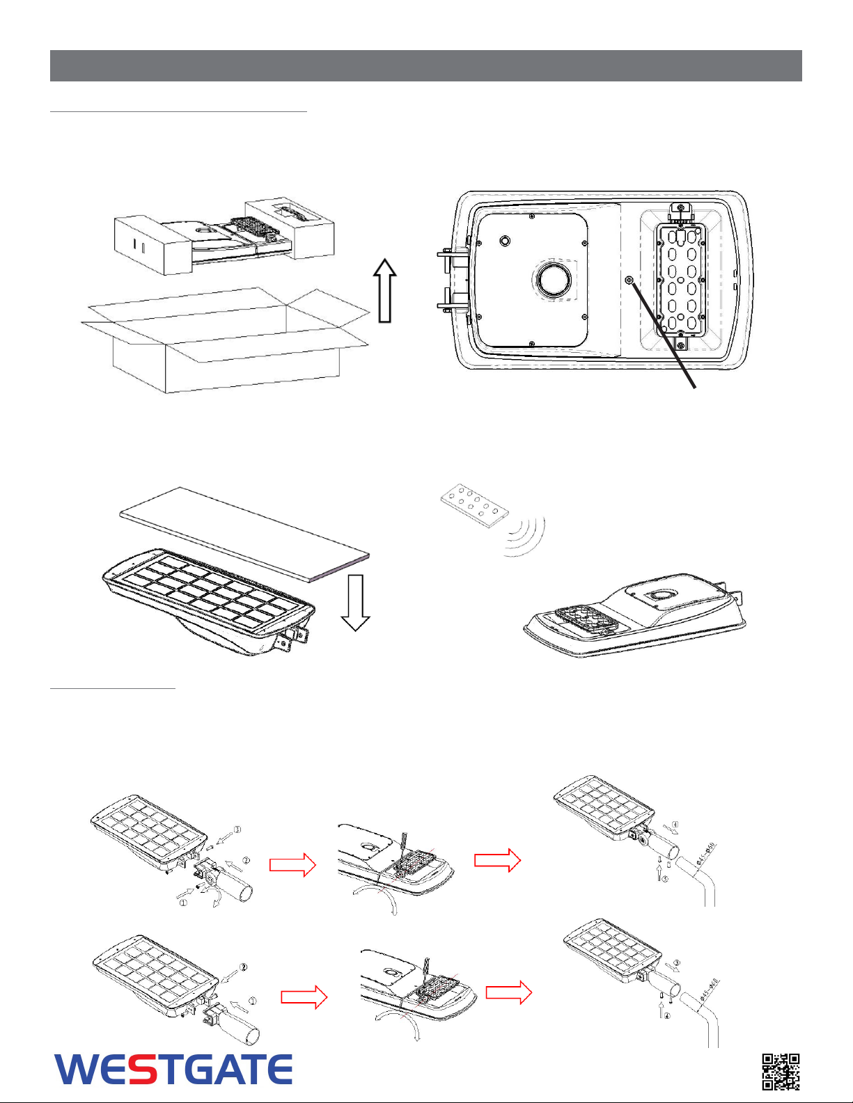
Red and green indicator
Microwave and PIR receiver
light-emitting
module
Charging point,
DC14.6V 5A MAX

3Phone: (877) 805-2252 | Fax: (877) 805-2252
www.westgatemfg.com |
Normal Outdoor Operation:
1. The light is charged and ready to work (Stand By Mode): Red indicator ashes slowly
2. The battery has less than 10% charge: Green indicator ashes fast
3. The light is on (Working Mode): Solid green indicator
4. 4.The xture/battery is defective: The Red indicator ashes fast
When charger (sold separately) is plugged-in:
5. The battery is charging (Stand By Mode): Red indicator ashes slowly
6. The xture/battery is defective: The Red indicator ashes fast
Remote Control Diagram Demonstration
INDICATOR GUIDE
1. Bi Level Setting:
2. Gradual Dim Settings :

4Phone: (877) 805-2252 | Fax: (877) 805-2252
www.westgatemfg.com
Average Daily Solar Radiation Per Month:
0°-13°
13°-26°
26°-37°
37°-46°
Increasing the tilt 15° in the winter or decreasing 15° in the summer gives the maximum sunlight for recharging the battery.
• The best facing direction for the solar panel is toward the south. facing west & east & or
north will provide less sunlight, resulting in a long time to charge the battery. The solar
charge will be less optimal if the installation is facing north.
> 9.0
8.5 - 9.0
8.0 - 8.5
7.5 - 8.0
7.0 - 7.5
6.5 - 7.0
5.0 - 5.5
6.0 - 6.5
4.5 - 5.0
5.5 - 6.0
4.0 - 4.5
kWh/m2/Day

1.
2.
3.
4. Ensure the On/O Button and the Test button has been pressed before installation.
5. Using the dedicated tool to assemble the light body and the mounting accessories, adjust the light xture and LED module toa
suitable angle.
6. Install the light to the round pole, square pole, or wall; tighten the screws and the nuts when xed
Installation steps
5Phone: (877) 805-2252 | Fax: (877) 805-2252
www.westgatemfg.com |
1.
2.
3. Cover the solar panel and check if the light module turns on
4. Press the test button on the remote control to test if the function is normal and set the necessary operation mode. Thelight
module will ash twice when receiving the signal from the remote control. The default setting is Induction mode20%-80%
Open the package and do inspection
Step By Step Installation guide
1. guide1.Take out the xture and the tools from the package.
2. Press the ON/OFF key on the remote control and check whether it shows red light on the sensor. If still not, use adedicated
charger to charge
Charging point, DC14.6V 5A MAX

6Phone: (877) 805-2252 | Fax: (877) 805-2252
www.westgatemfg.com
Select the correct operating mode according to the user’s needs and the local sunshine conditions.
conditionsIn case of battery failure or end of life, loosen the screws on the battery cover, disconnect the wire connectors, replace
the whole battery cover kit (including the smart control system, battery, and cover), connect the wires, and tighten the screws.
Adjustment steps
Replacement and Maintenance operations:

7Phone: (877) 805-2252 | Fax: (877) 805-2252
www.westgatemfg.com |
Mounting Accessories
Item Fixed arm
mounting
Slip tter
mounting U-Trunnion mounting Square-Hoop
Mounting
Round -Hoop
Mounting
17W Solar
Street light
1.Wall mounted
2.Square pole above
100mm
1.Round pole :
Φ50-Φ90mm
2.Square pole
50-90mm
Round pole:
Φ50-Φ110mm
36W Solar
Streetlight
1.Wall mounted
2.Square pole above
120mm
1.Round pole :
Φ60-Φ100mm
2.Square pole
50-100mm
Round pole:
Φ50-Φ120mm
54W Solar
Streetlight
This manual suits for next models
2
Table of contents
Popular Lantern manuals by other brands

HAMPTON BAY
HAMPTON BAY 28235 Use and care guide

EMU
EMU Cone Use instruction

HAMPTON BAY
HAMPTON BAY WQ1007-26B Use and care guide

RealFlame
RealFlame Outdoor Living 160 Redvale manual

LIVARNO LUX
LIVARNO LUX HG03508B Assembly, operating and safety instructions

REV
REV ANGLE LIGHT 55 Assembly and operating instructions