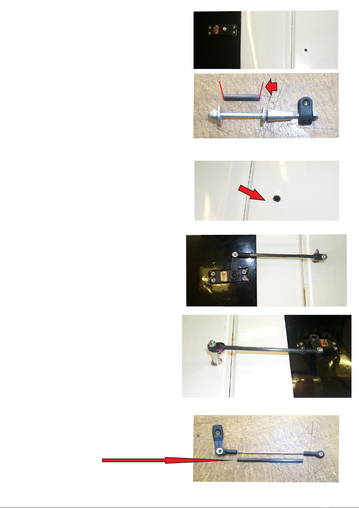
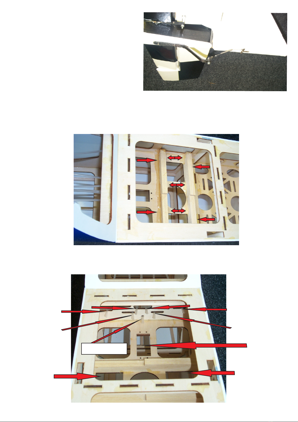
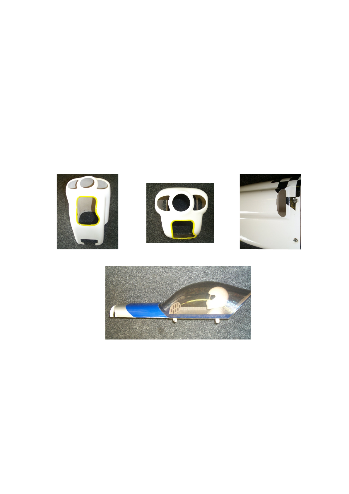
AILERON CONTROL HORN
Using the items as shown in the picture assemble
into the aileron. When you are happy and all set
up has been completed it is recommended to use
Weston Superlock to secure the bolt and nut
assembly.
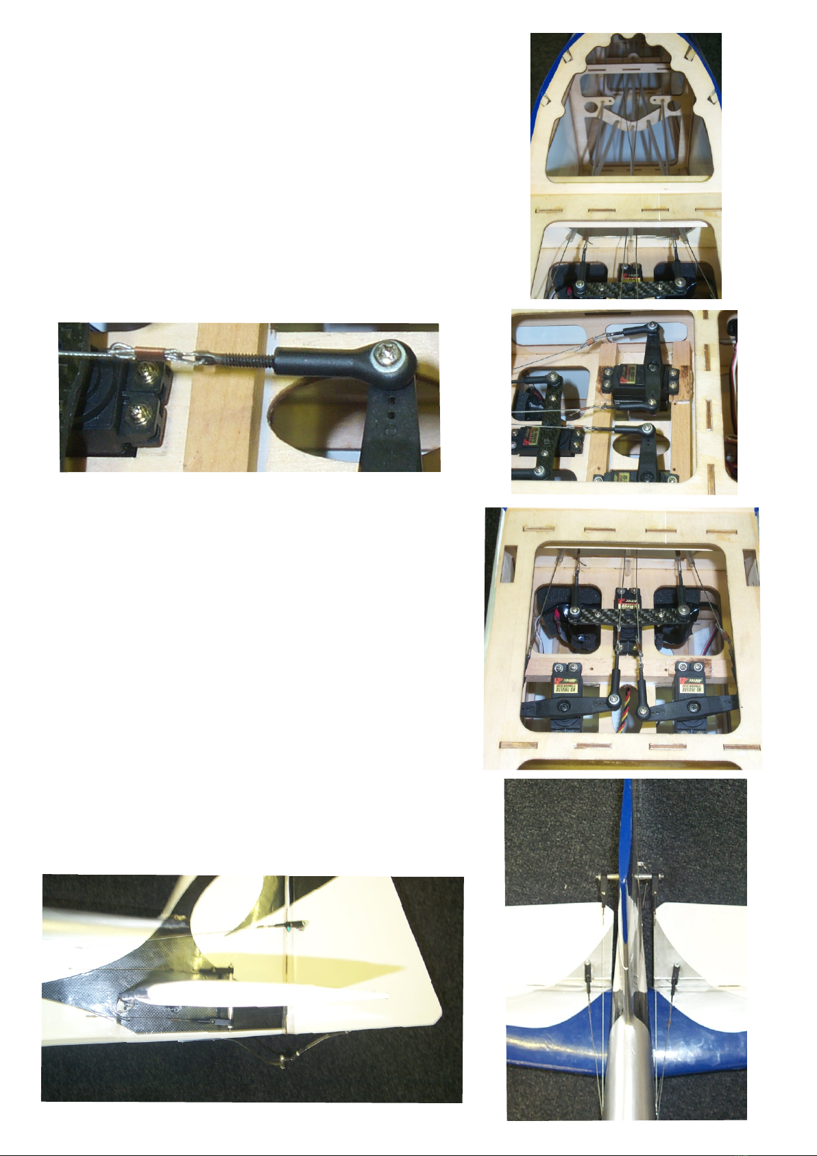
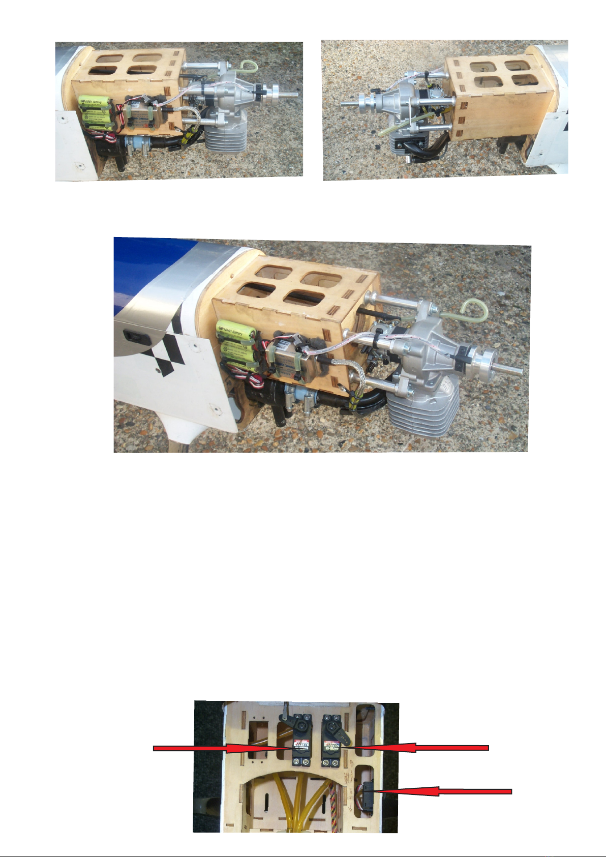
AILERON SERVOS
Pass the servo cable through the wing section to the
exit point in the centre of the wing. Install the servo so
the output arm is to the trailing edge of the wing and
screw into position. Take the aileron pushrods and
connect to the servo arm using the large ball link as
shown. Ensure that the servo and control surface are
both in the neutral position .
Control rod
With the servo installed and the control horn installed
and all in the neutral position make the control rod up
as shown. Using the supplied carbon tube cut to the
required length and wet assemble with slow cyano or
epoxy.
Repeat procedure on other aileron.
WE RECOMMEND DUBRO HEAVY DUTY
SERVO ARMS.
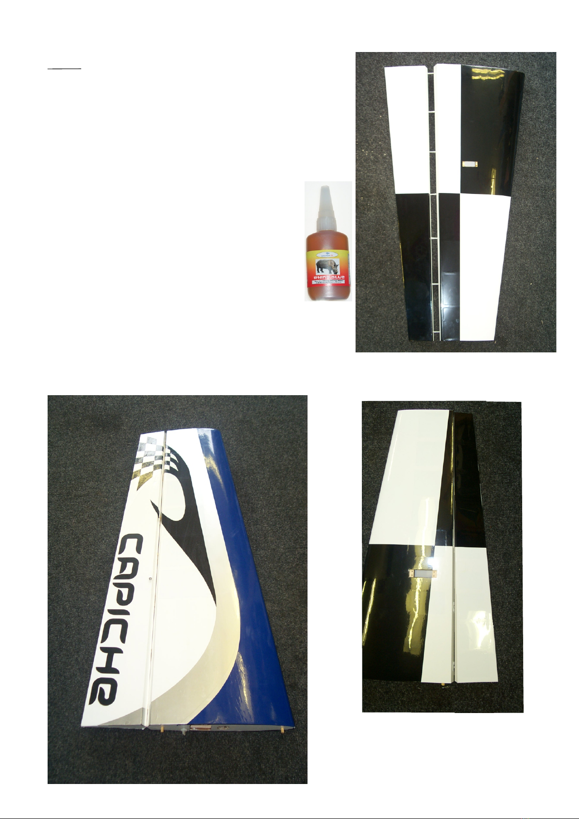
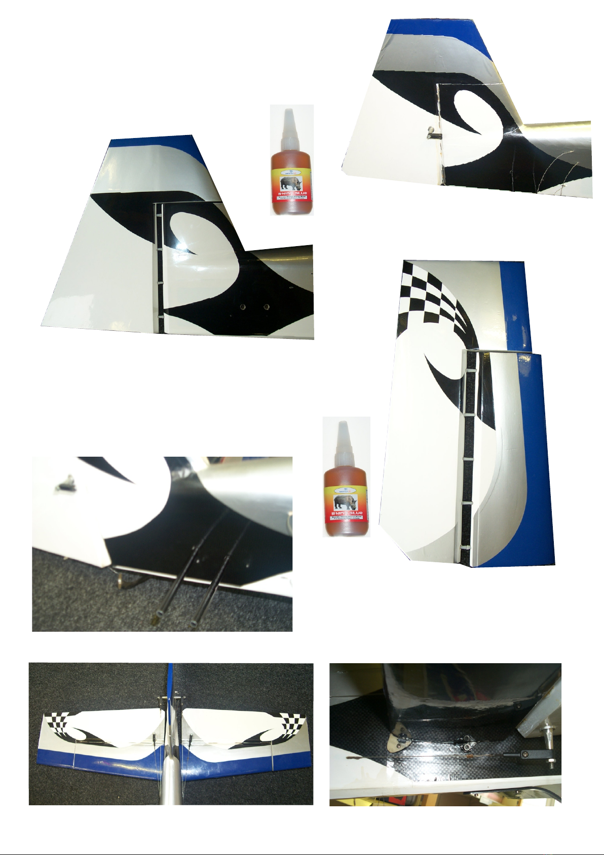
Carbon tube cut to length
Using the control horns as a guide mark out the
hardwood points in the control surfaces and drill to
accept the control horn bolts. Please ensure that
the hole you drill has sufficient hard wood area is
around it and not too close to the edge. Then with
the supplied carbon tube of 4mm ID cut to length
with a razor saw or cutting disk as per pic with angled
ends to sit at the same angle as the control surface
angle. Re-drill the control surface to accept the carbon
tube, the carbon tube is to sit just below the surface
so as not to take the main load but to stop
any compression of the aileron when the control
horn bolts are done up tight. When happy run some
thin cyano to lock carbon tube in place.
CUT AT THE SAME
ANGLE AS THE
AILERON
CARBON TUBE GLUED
IN PLACE