Weston UK MAGNUM R User manual

Tel: +44(0)1795 521030
Fax: +44(0)1795 522020
Vat Reg. No 217 2427 83
www.westonuk.co.uk
84 - 88, London Road,
Teynham,
Near Sittingbourne,
Kent. ME9 9QH.
England.
Before starting please check all components
Additional items requires for completion:
Radio gear, motor, prop, tuned pipe/silencer, cyno,
Epoxy resin, good quality tools and a very sharp blade!
WE RECOMMEND HITEC RADIO EQUIPMENT AS USED BY THE
WESTON UK DISPLAY TEAM:
Throttle HS 422 Ailerons HS 625 MG Eleveator HS 645 MG

Parts List
Fuselage
Wing
Tail fin
Tailplane x 2
Aileron servo mount (W18)
Elevator Servo mount (D23)
Elevator Servo Cover
Accessory Packs containing the following;
Fueltank
Engine mount
Throttle wire
Wing bolt
Engine Mount Bolts + washers
Elevator Pushrod inner x 2
Elevator Pushrod joiner
Elevator Pushrod insert x 2
Aileron Pushrods x 2
Snaplinks x 4
Quicklink (Metal) X 1 (For Elevator Pushrod Joiner)
Swing keeper x 2
Control horns x 2
2mm Screws x 4
Throttle Servo Brass Swivel Link

Wing
Place the Aileron mounting tray over the Servo cutout in the wing. Using a felt tip pen, mark the
edge of the mount and then cut away the covering film. Using cyno, stick the mounting plate to the
wing then screw the servo to the mounting plate. Screw the snaplinks to the Aileron pushrods then
attach the pushrods to the servo arm using the swingkeepers, adjust the length of the pushrod
accordingly.
Remove the ailerons from the hinges, cut away any excess covering from the hinge slots, push the
hinges halfway into ailerons, then put two drops of thin cyno onto the hinge (at the control surface),
allow to dry. Using epoxy, glue the aileron torque rod in and then gently push the aileron into the
wing, when a good fit is achieved (move freely) apply two drops of thin cyno to each hinge, turn the
wing over and repeat the process.
Push plastic bolt as supplied through the wing, cut a small piece of silicone tubing and push onto the
wing bolt. This will stop the bolt from dropping out in transit.
Fuselage
Aerial Tube
Push the throttle wire down the aerial tube out through the end of the fuselage, piercing the
covering.
Throttle
Install the throttle servo into the pre-cut servo mount (see diagram 1). Pass the throttle wire through
the hole in the firewall then attach the wire to the throttle servo (Z bend) to prevent the wire rubbing.
Notch out the front former.
Fueltank
Make up the fueltank (see Diagram 4), attach your desired tubing to the tank, then place the tank
into the tankbay wedging in place using foam. Ensure that the throttle wire does not bind/snag on
the tank or padding.
**Note ** We have identified a minor problem with the tank installation. You simply need to
notch out bulkhead no.1 to allow the tank to go 3mm deeper into the fuselage. Place the tank in the
aeroplane, mark around the corners where it touches the curved bulkhead and with a knife or dremel
relieve it, this allows the tank to sit deeper in the fuselage which solves the problem.
Tailfin
Place the tailfin in the slot. Using a knife (as the covering is black), mark around the fin where the
fuselage meets the fin. Remove the fin from the slot and carefully cut away the covering using a
sharp knife. Insert the fin back into the slot and using some slow cyno or epoxy carefully glue the
fin into the slot.
Battery Mounting
The battery is mounted on the ply frame in front of the wing mounting plate using Ty-raps and foam
padding. The battery should be slid up inside the canopy section to the desired position as this will
avoid any contact with the aileron servo and control rods.
Receiver
The receiver is placed under the canopy behind the balsa sheeting, wrap the receiver in foam before
wedging in place (slide backward towards rear of plane). Feed the aerial through the aerial tube and

Switch
Mount the switch harness in the switch hole provided on the side of the fuselage near the
receiver (on the opposite side to the exhaust/pipe), ensuring free movement of the
switch.
Engine mounting
Install engine onto the pre-drilled engine mount and secure with self tapping allen key
screws. Attach the throttle wire arm using the plastic snaplink supplied.
Also available for noise sensitive sites the Genesis mini pipe
If you have purchased the engine and kit package mount the tuned pipe to the fuselage
using the supplied mount and tiewrap, you should use a 4mm bolt and washer to fix the
pipe mounting to the fuselage (over the pre-installed reinforced area of the fuselage).
Join the pipe using the West moulded silicone joiner and tiewraps provided.
WEST EUROTECH V1 .50 ABN In
excess of
2.8BHP @ 21,500RPM
TUNED PIPE/MANIFOLD
AND SPINNER
(Spinner supplied for £6.95)

Tailplane and Elevator
The tailplane is in two halves and must be inserted into the fuselage which has a pre-set
anhedral. Once inserted mark the film with a pen along the points at which the film has to be
removed. Once removed from fuselage remove film and re-install to ensure good fitment.
When happy with the fitment apply gap filling cyano or “wet assemble” with epoxy.
Remove the elevator from the hinges, cut away any excess covering from the hinge slots,
push the hinges halfway into elevator, then put two drops of thin cyno onto the hinge (at the
control surface), allow to dry. Gently push the elevator into the tailplane, when a good fit is
achieved (move freely) apply a few drops of thin cyno to each hinge, turn the tailplane over
and repeat the process.
Using the screw supplied and 5 min epoxy secure elevator mounting plate (D23) to the
fuselage behind the wing mounting bolt (see diagram 2) and drill and mount elevator servo.
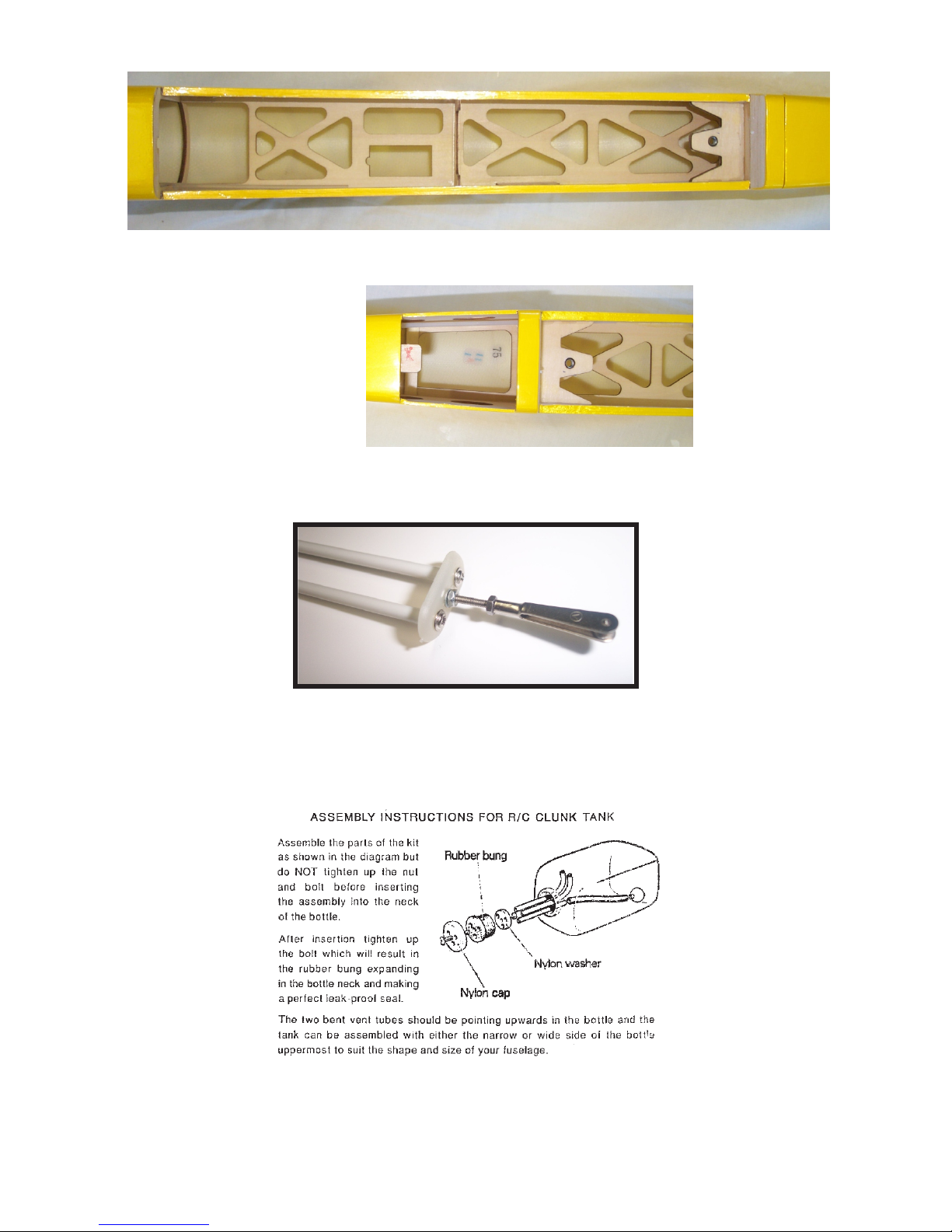
Assemble the pushrods and joiners (see diagram 3). Push the rods through the tubes and
connect to servo, ensuring servo is in neutral position.
The pushrods will overlap the elevator, using this as a guide attach the control horns at the
same angle as the pushrods. Ensure that the front of the horn is flush to the chamfer on the
elevator, then drill and bolt in place.
Trim the pushrods as required, then push the metal rod into the pushrod. This is done easily if
you remove the pushrods from the fuselage and hold the metal rod in a vice or pliers and
screw metal rod into the plastic. Refit the pushrods then fit the snaplinks and fix to the control
horns.
Manually move the elevator by pushing the pushrod to ensure that they move freely (bend
metal rods slightly in the tube to facilitate free running).
Install the elevator hatch and mark out the center point at the rear of the hatch. Drill a hole
5mm from the rear of the hatch and through the tongue on the underside ensuring that the
installed elevator control system is not drilled or damaged. Secure hatch with screw supplied.
General Information
PLEASE NOTE:- We recommend you seal all round the edges of the covering with
Tufkote to ensure no covering will lift during high speed flight.
C of G; this should be 135 - 145mm from the wingroot.
Movements; Elevator 10mm up and down
Ailerons 8mm up and down
The MagnumR is very stable and likes long fast sweeping manoeuvres. We suggest you have
someone to launch the model for the first few flights until trimmed and you have become
familiar with the Magnum.
If fitted with the WEST EUROTEC .52 V1, you will soon have no problem in launching the
model on your own.
We suggest that for the first few flights you use an APC 9 X 6/7 prop, for you to get used to
the general feel of the plane. Then for ultimate performance use an APC 8 x 8 prop.

Diagram 1 - Throttle servo mounting plate, D23
Diagram 3 - Elevator pushrod joiner
Diagram 4 - Fueltank Assembly details
Diagram 2 - Elevator servo
Please use 5
min epoxy and
screw to secure
elevator servo
tray
Table of contents
Other Weston UK Toy manuals
Popular Toy manuals by other brands

Faller
Faller 120129 quick start guide

Hasbro
Hasbro Play-Doh Disney FROZEN Sister Snow Magic manual

MGA Entertainment
MGA Entertainment Poopsie Dancing Unicorn 571162 Quick start quide

Mattel
Mattel Escape from Frank instructions

Lionel
Lionel Hudson Jr. owner's manual

WM aerobatics
WM aerobatics YAK55M SEPP instruction manual