Weston UK Hype 3D R User manual

The latest in Weston UK's range of high performance ARTF kits to
provide the ultimate in freestyle and 3D performance.
READ THE INSTRUCTIONS FULLY BEFORE COMMENCING!
IF UNSURE ABOUT ANY STAGE OF ASSEMBLY PLEASE CONTACT WESTON UK.
MATERIALS REQUIRED FOR COMPLETION:
Motor (.52 size 2 stroke) recommended motor West Eurotech 52T1 + Genesis pipe
APC 13x4w / 12 1/4 x 3 3/4 Prop
4 stroke engine .80-90 (Tuned By West)
Electric West 590kv motor, West 85A bec control, APC 16x8E
4cell or 5 cell 3700/4700ma lipo
Weston UK thin, thick Cyano
Good quality tools and a very sharp blade.
WE RECOMMEND HITEC RADIO EQUIPMENT AS USED BY
THE WESTON UK DISPLAY TEAM.
Recommended servos:
Throttle HS 311 Elevator, Ailerons HS 5625MG Rudder HS 5625MG
www.westonuk.co.uk

KIT CONTENTS
BAG 1
1 x MOTOR BOX
4 X WASHERS
4 X 4MM X 60MM BOLTS
BAG 2
2 X ENGINE MOUNTS
4 X 3MM X 20MM BOLTS
8 X WASHERS
4 X 3MM NYLOCKS
4 X 3MM X 25MM BOLTS
BAG 4
2 X AILERON PUSH RODS
1 X THROTTLE PUSH ROD
BAG 5
1 X SPINNER
BAG 6
1 X TAIL WHEEL ASSEM
6 X CONTROL HORNS
2 X CONTROL HORNS WITH
BACK PLATES
1 X WING BOLT
3 X SWING KEEPERS
9 X CLEVESIS
17 X HINGES
9 X CLEVIS KEEPERS
BAG 7
1 X CLOSED LOOP WIRE
2 X M4 X 40MM BOLTS (U/C)
2 X AF BOLTS 20MM (U/C)
4 X M4 NYLOCKS (U/C)
4 X M4 WASHERS (U/C)
6 X AF X 13MM CAP HEADS
(COWLING AND CANOPY)
15 X 2MM X 20MM BOLTS (
CONTROL HORNS)
15 X 2MM NUTS
(CONTROL HORNS)
6 X CLEVIS ADJUSTERS
2 X BOLTS
12 X CRIMPS
BAG 3
2 X WHEELS

RECOMMENDED MOTOR PACKAGES
ELECTRIC PACKAGE
WEST 590KV MOTOR
WEST 85A BEC CONTROLER
4 CELL OR 5 CELL
3700MAH / 4700MAH
APC 16X8 PROP
IC PACKAGE
WEST EUROTECH 52 T1
GENESIS MINI PIPE
“TIME TO BUILD”
Before starting please check all components.
WING
AILERONS
Each aileron has four hinge points pre-cut. Carefully insert the hinges supplied in the accessory pack into the
aileron ensuring that the hole is clear and free. Repeat procedure on all the aileron holes and when happy
install the aileron to the wing to ensure everything aligns. Remove all the hinges and glue them into place in
the aileron with super thin cyano ensuring they are in the correct orientation. When you are happy glue the
aileron into the wing so there are no gaps between the wing and the aileron and there is no binding at the
edges. Repeat procedure on other aileron.
Ensure once assembled there are no gaps and no binding
If any glue has run down the wing or aileron this can be removed with Cyano
Wipe available from
Weston uk.
ATTENTION!!!!!!!
PLEASE RUN THIN CYANO INTO
THE WING ON THE JOINING POINT
OF THE WING RESTRAINT TO ENSURE
IT CANNOT MIGRATE OUT AND CAUSE
THE WING TO COME OFF DURING FLIGHT

AILERON SERVOS
Install a small draw wire through the wing section very carefully ensuring you do not catch any ribs and draw the
servo cable through the wing section to the exit point in the centre of the wing. Install the servo so the output arm is
to the leading edge of the wing and screw into position. Take the two aileron pushrods supplied and attach clevises
to the threaded ends. With your servo in the neutral position clip the pushrod onto the servo arm. You can now use
this to align the position of your aileron control horns on the aileron over the strengthening points. Once the
position has been found, ensuring the clevis attachment point on the horn is positioned over the hinge line secure
into position by drilling and bolting the control horn and backing plate together. Repeat procedure on other
aileron.
FIN
Insert fin into fuselage so that the rudder can move full travel both ways. Carefully mark out the position of the
joints with a pen and remove fin from fuselage and carefully remove the film using a very sharp knife, ensuring
that you do not cut into the wood, to make a good balsa to balsa glue joint. Refit the tail fin and using thin cyano
glue into position.
RUDDER
The rudder utilizes a closed loop control system. Slide the tailwheel bracket into the fin post to ensure that it aligns
with the rudder. When you are happy insert the tailwheel bracket and cyano into position. Align the rudder to the
fin. Mark and drill the rudder to accept the steering rod of the tailwheel. Insert the hinges into the rudder into the
pre-cut holes and repeat procedure as per ailerons. Run some slow cyano on the tailwheel steering rod while
assembling rudder to fin. Attach control horns into position on the rudder so that when the closed loop wires exit
the fuselage they do not run at an acute angle so as to lessen any binding but also with clearance for full up elevator
. Attach control horns on both sides of the rudder over the strengthened area and bolt into position ensuring correct
alignment over the hinge line. Please note that the rudder horns are better fitted after the stabiliser is fitted.
TAILPLANE
Insert the tailplane into the fuselage slot ensuring correct alignment. When happy mark out the joining points with
a pen and remove tailplane. Using a very sharp knife remove film, ensuring you do not cut into the wood, to make
a good balsa to balsa glue joint. Reinstall tailplane and using thin cyano glue into position.
ELEVATOR
The elevator utilizes a closed loop control system.
Attach elevator to tailplane as per ailerons using
the hinges provided. Once installed attach the
Control horns to the elevator using the
same method as per rudder.
Cut film away

UNDERCARRIAGE/SPATS
Insert 4mm bolt through the recessed side of the wheel then screw nylock nut onto bolt so that the bolt begins to make
the thread into the nylon section of the nut. Once this is achieved take the nut back off the axle and turn it round so the
nylon part of the nut goes onto the axle first. This is then tightened up until it is 2mm from the wheel hub. Push bolt
through undercarriage and using the second nylock nut and washer fasten to undercarriage leg. Slide spat over wheel
and bolt and fix spat to undercarriage leg using small self - tapping screws. You may find that once you have installed
the screw you have to remove it and cut it down so it does not bind against the wheel. Repeat procedure on other spat.
See picture 4. Attach undercarriage to fuselage using the two bolts and washers provided.
ELEVATOR SERVO
Install the servo in the rear servo tray so the servo arm is rear most. Pass the closed loop wire through one of the
elevator outlet holes at the rear of the fuselage, along inside the fuselage and to one side of the servo. Before going
through the servo horn slide a crimp down the cable then pass the cable through the servo horn and back through the
crimp. The cable is then passed through the fuselage to the opposite elevator to which you passed the cable into.
Terminate the cable at the control horn as per the rudder using the clevis and clevis adjuster and secure the crimp at
the servo horn and carry out the same to the other control wire .
Some people find it very hard to understand closed loops on elevator. A simple way to think about it is the two top
control horns of the elevator are linked to one side of the servo horn and the two bottom control horns are linked to the
opposite side of the servo horn.
RUDDER SERVO
Install the rudder servo forward most with the output arm rear most. Pass the wire through the fuselage from the
rudder outlet point to the servo arm. Terminate the cable at the servo arm using the crimp only. Terminate the cable
at the rudder end with the crimp, clevis adjuster and clevis. These items are always external to allow easy
adjustment. Ensure when doing so that the rudder and servo are in the neutral position. Repeat procedure on other
control wire .
Closed loop terminated with
clevis, clevis adjuster and crimp
at the control surface.

MOTOR
Using the supplied bolts, nuts and washers attach the engine mount to the firewall via the capture nuts pre installed
as per picture.
Mount your chosen motor (West 52T1 recommended) to the supplied mount ensuring that when you fit the cowling
the prop drive protrudes past the cowling. Please note the pipe is at 6 o'clock and the cylinder head will be at seven
o'clock. If you are fitting the West 52 T1 the engine will need to be at the very end of the engine mount as shown in
picture and when fitting cowling you may be required to elongate the fixing holes just a little for spinner alignment.
FUEL TANK
Make the fuel tank up as per picture .Once you are happy with your fuel tank install it into the
fuel bay with some foam. It will be necessary to fuel proof the engine box and fuel tank bay to
eliminate fuel contamination.
IC MOTOR INSTALATION

THROTTLE SERVO AND PUSH ROD
Slide the throttle guide tube through the firewall and down the side of the tank into the servo bay area. Allow about
10mm to protrude forward of the firewall. Once in position glue the outer guide tube to the firewall point and support.
Install clevis on the threaded end of the throttle control rod and install into tube. You will have to put a set in the control
rod to ensure a good alignment with the throttle arm ensuring no metal to metal contact. Terminate the other end of the
control rod to the servo arm with the swing keeper as per picture.
Cut cowling for your engine as per picture

ELECTRIC MOTOR INSTALATION
Before installing the electric motor box we
recommend running medium or thick cyano
around the inside of the motor box to ensure
good security. The holes are pre-drilled for our
west 590kv motor and mount so you may have to
adjust if you are using something else. Using
the bolts provided in the motor pack and capture
nuts pre installed install the electric motor box
and motor to the fire wall.
For added security you can glue the electric
motor box to the fire wall as well as bolting it.
Secure your speed controller to the under side of the
box work using velcro and tie-wraps. A
small hole will need to be made from the speed
control tray to the tank bay to pass the cables up.
We recommend you open 1 of the air outlets at the bottom
of the fuselage but you do have three if you wish to do so.
Cooling requirements
We recommend you cut the bottom of the
cowling for the speed controller
Insert the pre moulded scoop inside the cowling
to re-direct airflow onto the motor.
Cut out the cooling holes on the side of the fuselage
behind the cowling and stick on the cooling scoops
for the battery cooling.

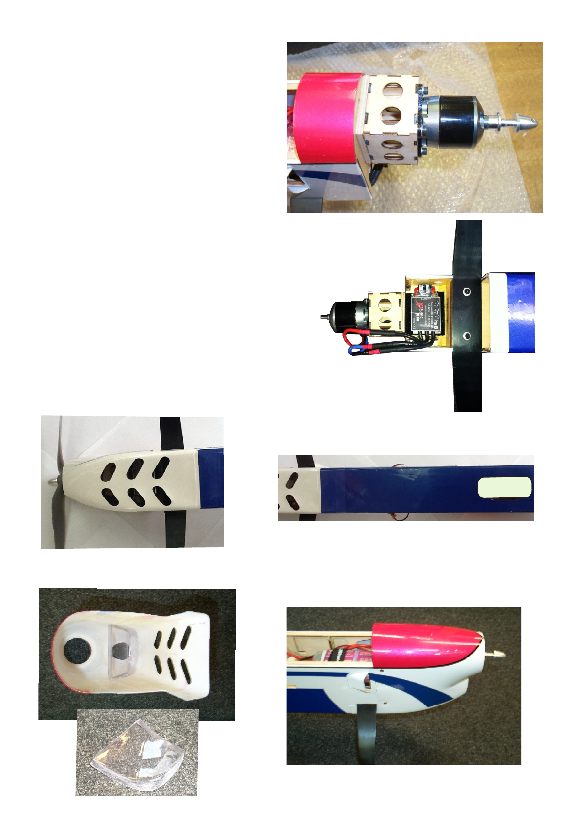
Battery installation
Depending on your chosen lipo 3 cell or 4 cell
will depend on where it is placed for your
required C of G. But once established it is a
good idea to install a small strap and velcro
to eliminate the movement of the battery.
SWITCH INSTALLATION
Install your receiver switch in the pre-cut slot in the side of the fuselage
COWLING
Once all holes have been cut and you are happy that there is no interference install cowling with bolts and
washers.
CANOPY
Install canopy to the hatch with Weston canopy glue or the self tappers provided.
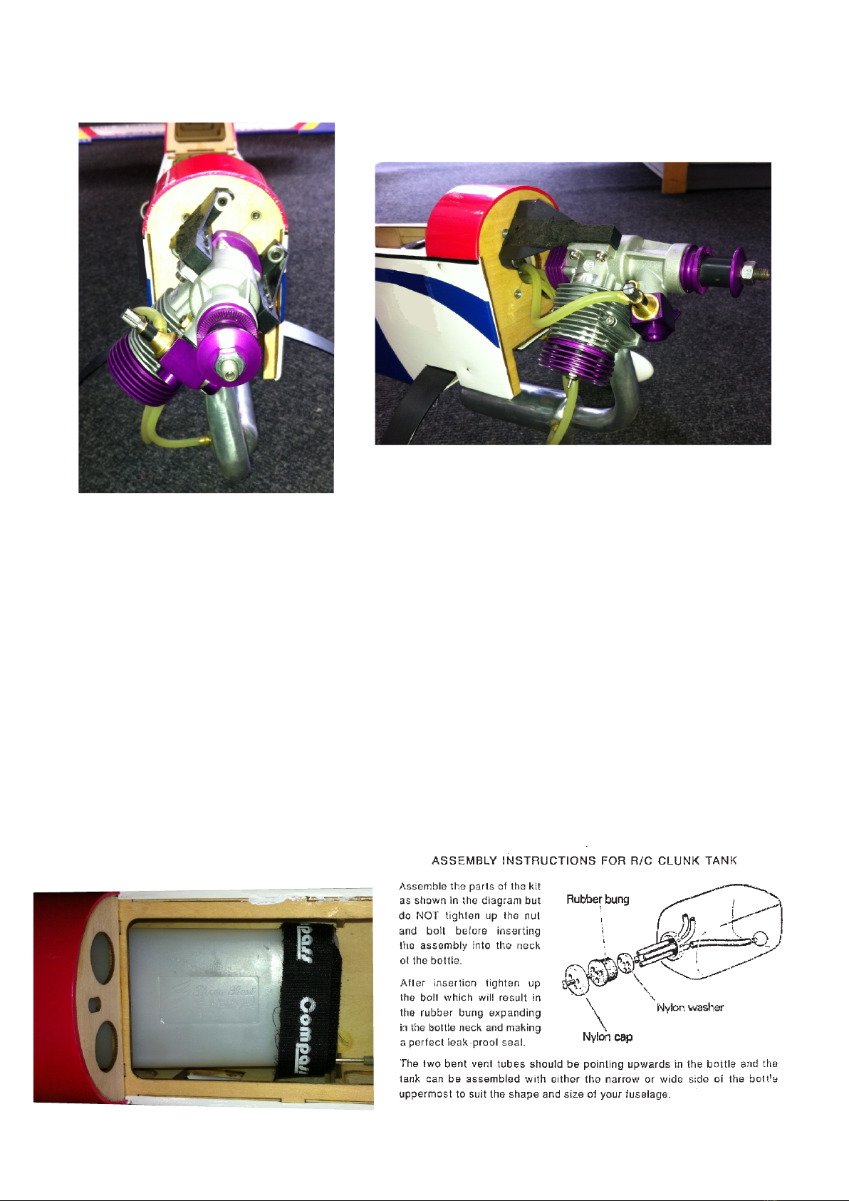
RX BATTERY INSTALLATION(IC VERSION)
The battery installation will vary depending on engine used and C.G position require. A good starting point is
just behind the Rx, but if you want extreme 3D then behind the elevator servo which you will have to tie-wrap
it to the rear servo frame.
RX INSTALLATION
The Rx should be installed in foam and with all leads secured. A good position is just behind the spar.
SET UP
Use the nicad to adjust the C of G. The range for normal use is between and 140mm and up to 155mm for
experts - from the leading edge of the wing.
CONTROL MOVEMENT SET UP MEASURED FROM IN-BOARD POINTS
Intermediate : ailerons 25mm up and down EXPEDENTIAL
elevator 25mm up and down Intermediate: 15% - 30%
rudder 45 degrees side to side Expert 25% - 50%
Advanced: ailerons Max throw
elevator Max throw
rudder Max throw
FLAPERONS
It is not necessary to have flaperons but these can give incredibly tight loop manoeuvres.
WARNING
On take off and landing beware not to apply full elevator as this may cause damage to the elevator in long
grass.
REMEMBER
Before flying check your model and do a thorough range check. Check all electrical connections are solid and
restrained and the receiver is in a padded area.
We trust you will have many happy hours of flying this model!!
Weston UK, 84-88 London Rd, Teynham, Sittingbourne, Kent Me9 9QH, England
Tel: +44(0)1795 521030 Fax or Tel: +44(0)1795 522020, E- mail alan@westonuk
www.westonuk.co.uk
Quick release canopy option
If you have chosen the electric route you can easily
make a quick release canopy. Simply knock out the
capture nuts and use an inner and outer control rod
snake and a bit of fuel tubing at the ends.
Table of contents
Other Weston UK Toy manuals
Popular Toy manuals by other brands

Fisher-Price
Fisher-Price 2031 manual

Talk To Me Technologies
Talk To Me Technologies wego A quick reference

REVELL
REVELL KIT 2835 Assembly manual

Eduard
Eduard Fw 109A-8/R11 Assembly instructions

MODSTER
MODSTER Arrows HOBBY TWIN 64MM F-15 operating manual

Eduard
Eduard BRASSIN 632002 F-4B/J/N/S seat 1/32 Assembly manual