Weston 2VL1 User manual

© 2019 Weston Precision Audio
1
2VL1
Dual VCO + LFO
DIY Eurorack Module
Weston Precision Audio
Designed In Portland, Oregon
Revision 03 - August 29 2019

DESCRIPTION
The 2VL1 is a compact (12HP) Eurorack
format synthesizer module which
includes 2 VCOs and 1 simple LFO. The
2VL1 was designed with the idea of
providing a lot of sound out of a small
space, and for a low price. The unit is
designed to be DIY friendly by
incorporating all through hole
components, all of which are readily
available and low-cost. The 2VL1 is
configured to use a THAT Corporation
matched transistor array and tempo
resistors for the 2 exponential converters
for exceptional thermal stability
SPECS
VCO 1 outputs: Pulse, Saw, & Triangle
VCO 2 outputs: Pulse & Saw
LFO outputs: Triangle & Square
VCO1 & 2 inputs: 1 Volts/Octave*,
Pulse Width Modulation, Linear
Frequency Modulation
*VCO 2 will default to using the VCO 1 Volts/
oct input until a jack is installed into VCO 2
Volts/oct.
VCO 2 Sync: Switchable to Off, synced
from VCO 1, or externally synced*
*For best results supply a 10Vpp sawtooth or
triangle wave. Sync works best when VCO2’s
frequency is higher than the master waveform
and that the sync waveform is in the C3-C5
range.
SPECS, cont.
All wave outputs: 10 Volts peak-to-peak
VCO 1 range: 1Hz - 20kHz
VCO 2 range; 1Hz - 20kHz
LFO range: 20s (.05mHz) - 30Hz
Power input: +12V & -12V via standard
10 pin Eurorack connector.
Power consumption (+12V / -12V):
55mA / 52mA
Tuning error: < 4 Cents (typical from C0
to C7):
© 2019 Weston Precision Audio
2

© 2019 Weston Precision Audio
3
PCB-A
PCB-B
PCB-B
M3 Hex Standoff,
4mm x 12mm L
Typ
Phillips Machine Screw
M3 x 6mmL, Typ
Front Panel
Davies Clone Knobs
(See build instructions
for color requirements)
Round Nuts For
Thonkiconn 3.5mm Jacks, Typ
Potentiometer Hardware, Typ
2VL1 Mechanical Explode View

BUILD INSTRUCTIONS
Begin by stuffing PCB-A using the table
below.
Start with diodes, resistors, ferrite
beads, then caps, then DIP sockets and
connectors, and finally transistors and
trimpots.
© 2019 Weston Precision Audio
4
2VL1 PCB-A Rev AC Stuffing
Reference
Quantity
Value
Footprint/Note
C10 C11
2
10n Film (WIMA)
Capacitor_THT:C_Rect_L7.0mm_W6.0mm_P5.00mm
C14
1
22u Tantalum Axial
Install with negative leg to ground hole (hole closer to edge of board).
Positive leg has the chamfer.
C15 C16 C17
3
33u Electrolytic
Capacitor_THT:CP_Radial_D5.0mm_P2.50mm
C1 C18 C2
3
0.1u Film
Capacitor_THT:C_Rect_L7.0mm_W2.5mm_P5.00mm
C5 C6
2
0.001u Film
Capacitor_THT:C_Rect_L7.0mm_W2.5mm_P5.00mm
C7
1
680p MLCC
Capacitor_THT:C_Disc_D3.0mm_W1.6mm_P2.50mm
C12 C13 C3 C4 C8 C9
6
0.01u Film
Capacitor_THT:C_Rect_L7.0mm_W2.5mm_P5.00mm
D2 D3
2
1N914
Diode_THT:D_A-405_P7.62mm_Horizontal
D1 D4
2
4148
Diode_THT:D_A-405_P7.62mm_Horizontal
J1
1
RECEPTICAL - IO 1
2x8 Pin Socket / Make sure it is installed level and square on silk side!
J2
1
RECEPTICAL - IO 2
2x8 Pin Socket / Make sure it is installed level and square on silk side!
J3
1
Eurorack Power
Connector_Multicomp:Multicomp_MC9A12-1034_2x05_P2.54mm_Vertical
L1 L2
2
Ferrite Bead
Inductor_THT:L_Axial_L5.3mm_D2.2mm_P7.62mm_Horizontal_Vishay_IM-1
Q1 Q2
2
2N3904
Package_TO_SOT_THT:TO-92
R11
1
22K
Resistor_THT:R_Axial_DIN0207_L6.3mm_D2.5mm_P7.62mm_Horizontal
R1 R2
2
2M
Resistor_THT:R_Axial_DIN0207_L6.3mm_D2.5mm_P7.62mm_Horizontal
R8 R12
2
1M
Resistor_THT:R_Axial_DIN0207_L6.3mm_D2.5mm_P7.62mm_Horizontal
R10 R13 R27
3
820R
Resistor_THT:R_Axial_DIN0207_L6.3mm_D2.5mm_P7.62mm_Horizontal
R14 R19
2
5.1K
Resistor_THT:R_Axial_DIN0207_L6.3mm_D2.5mm_P7.62mm_Horizontal
R15 R17
2
8.45K
Resistor_THT:R_Axial_DIN0207_L6.3mm_D2.5mm_P7.62mm_Horizontal
R18 R21
2
33K
Resistor_THT:R_Axial_DIN0207_L6.3mm_D2.5mm_P7.62mm_Horizontal
R20 R22
2
412K
Resistor_THT:R_Axial_DIN0207_L6.3mm_D2.5mm_P7.62mm_Horizontal
R24 R28
2
200K
Resistor_THT:R_Axial_DIN0207_L6.3mm_D2.5mm_P7.62mm_Horizontal
R30
1
51K
Resistor_THT:R_Axial_DIN0207_L6.3mm_D2.5mm_P7.62mm_Horizontal
R31 R32 R37
3
47K
Resistor_THT:R_Axial_DIN0207_L6.3mm_D2.5mm_P7.62mm_Horizontal
R33
1
75K
Resistor_THT:R_Axial_DIN0207_L6.3mm_D2.5mm_P7.62mm_Horizontal
R34 R40
2
1K
Resistor_THT:R_Axial_DIN0207_L6.3mm_D2.5mm_P7.62mm_Horizontal
R35
1
1.5K
Resistor_THT:R_Axial_DIN0207_L6.3mm_D2.5mm_P7.62mm_Horizontal
R36
1
12K
Resistor_THT:R_Axial_DIN0207_L6.3mm_D2.5mm_P7.62mm_Horizontal
R38
1
24K
Resistor_THT:R_Axial_DIN0207_L6.3mm_D2.5mm_P7.62mm_Horizontal
R16 R39
2
10K
Resistor_THT:R_Axial_DIN0207_L6.3mm_D2.5mm_P7.62mm_Horizontal
R26 R41
2
100K
Resistor_THT:R_Axial_DIN0207_L6.3mm_D2.5mm_P7.62mm_Horizontal
R3 R5
2
2K TEMPCO
Resistor_THT:R_Axial_DIN0207_L6.3mm_D2.5mm_P7.62mm_Horizontal
R4 R7
2
47R
Resistor_THT:R_Axial_DIN0207_L6.3mm_D2.5mm_P7.62mm_Horizontal
R6 R9
2
220K
Resistor_THT:R_Axial_DIN0207_L6.3mm_D2.5mm_P7.62mm_Horizontal
TP1 TP2
2
100R
Potentiometer_THT:Potentiometer_Bourns_3266Z_Horizontal
TP3 TP4 TP5 TP6
4
100K
Potentiometer_THT:Potentiometer_Bourns_3266Z_Horizontal
U1
1
TL084
Package_DIP:DIP-14_W7.62mm_Socket
U2 U6
2
TL082
Package_DIP:DIP-8_W7.62mm_Socket
U3
1
THAT320P14-U
Package_DIP:DIP-14_W7.62mm_Socket
U4
1
CD40106
Package_DIP:DIP-14_W7.62mm_Socket
U5
1
LM13700
Package_DIP:DIP-16_W7.62mm_Socket
1

BUILD INSTRUCTIONS, cont.
Next, stuff PCB-B using the same parts
order as the previous board.
© 2019 Weston Precision Audio
5
2VL1 PCB-B Rev AD Stuffing
Reference
Quantity
Value
Footprint/Note
C19 C20 C21 C22 C23 C24 C25 C26
8
0.01u Film
Capacitor_THT:C_Rect_L7.0mm_W2.5mm_P5.00mm
C27 C28
2
1.5u Film
Capacitor_THT:C_Rect_L7.0mm_W2.5mm_P5.00mm
J1
1
PINHEADER - IO 1
2x8 Pin Header / Make sure it is installed square and straight on the
silkscreen side of board
J2
1
PINHEADER - IO 2
2x8 Pin Header / Make sure it is installed square and straight on the
silkscreen side of board
J3
1
RECIPTICAL - IO 3
2x4 Pin Receptical / Make sure it is installed square and straight on the
silkscreen side of board
J4
1
RECIPTICAL - IO 4
2x4 Pin Receptical / Make sure it is installed square and straight on the
silkscreen side of board
J5
1
RECIPTICAL - IO 5
2x4 Pin Receptical / Make sure it is installed square and straight on the
silkscreen side of board
Q3 Q4
2
KSC945
Package_TO_SOT_THT:TO-92
R42
1
33K
Resistor_THT:R_Axial_DIN0207_L6.3mm_D2.5mm_P7.62mm_Horizontal
R44
1
9.1K
Resistor_THT:R_Axial_DIN0207_L6.3mm_D2.5mm_P7.62mm_Horizontal
R45
1
56K
Resistor_THT:R_Axial_DIN0207_L6.3mm_D2.5mm_P7.62mm_Horizontal
R46 R49
2
360K
Resistor_THT:R_Axial_DIN0207_L6.3mm_D2.5mm_P7.62mm_Horizontal
R48
1
7.5K
Resistor_THT:R_Axial_DIN0207_L6.3mm_D2.5mm_P7.62mm_Horizontal
R51
1
37.4K
Resistor_THT:R_Axial_DIN0207_L6.3mm_D2.5mm_P7.62mm_Horizontal
R52 R53
2
150K
Resistor_THT:R_Axial_DIN0207_L6.3mm_D2.5mm_P7.62mm_Horizontal
R54 R55
2
2K
Resistor_THT:R_Axial_DIN0207_L6.3mm_D2.5mm_P7.62mm_Horizontal
R22 R25 R43 R47 R50 R60 R61 R64 R66
9
100K
Resistor_THT:R_Axial_DIN0207_L6.3mm_D2.5mm_P7.62mm_Horizontal
R62 R63
2
2M
Resistor_THT:R_Axial_DIN0207_L6.3mm_D2.5mm_P7.62mm_Horizontal
R56 R57 R58 R59 R68 R70
6
10K
Resistor_THT:R_Axial_DIN0207_L6.3mm_D2.5mm_P7.62mm_Horizontal
R69 R71
2
3K
Resistor_THT:R_Axial_DIN0207_L6.3mm_D2.5mm_P7.62mm_Horizontal
R72 R73
2
2.2K
Resistor_THT:R_Axial_DIN0207_L6.3mm_D2.5mm_P7.62mm_Horizontal
R74 R75
2
191K
Resistor_THT:R_Axial_DIN0207_L6.3mm_D2.5mm_P7.62mm_Horizontal
R76 R77 R78 R79
4
1K
Resistor_THT:R_Axial_DIN0207_L6.3mm_D2.5mm_P7.62mm_Horizontal
TP7 TP9
2
100K
Potentiometer_THT:Potentiometer_Bourns_3266Z_Horizontal
U7 U9
2
TL084
Package_DIP:DIP-14_W7.62mm_Socket
U10 U8
2
TL082
Package_DIP:DIP-8_W7.62mm_Socket
1

BUILD INSTRUCTIONS, cont.
Finally, stuff PCB-C using the same parts
order as the previous board. Leave the
pots and LEDs off for now.
**If you are using the LEDs on the
BOM, use 47k for R90 and 10k for R91.
© 2019 Weston Precision Audio
6
2VL1 PCB-C Stuffing
Reference
Quantity
Value
Footprint/Note
C27 C28 C29
3
0.47u MLCC
Capacitor_THT:C_Disc_D3.0mm_W2.0mm_P2.50mm
C30
1
150u Al Polymer
Capacitor_THT:CP_Radial_D6.3mm_P2.50mm
D5 D6
2
LED
LED_THT:LED_D3.0mm
J12
1
VCO1 V/OCT IN
Jacks:Thonkiconn Mono Jack / Install square and level!
J13
1
VCO2 V/OCT IN
Jacks:Thonkiconn Mono Jack / Install square and level!
J14
1
PWM1 IN
Jacks:Thonkiconn Mono Jack / Install square and level!
J15
1
FM1 IN
Jacks:Thonkiconn Mono Jack / Install square and level!
J16
1
PWM2 IN
Jacks:Thonkiconn Mono Jack / Install square and level!
J17
1
FM2 IN
Jacks:Thonkiconn Mono Jack / Install square and level!
J18
1
SYNC IN
Jacks:Thonkiconn Mono Jack / Install square and level!
J19
1
SAW1 OUT
Jacks:Thonkiconn Mono Jack / Install square and level!
J20
1
TRI1 OUT
Jacks:Thonkiconn Mono Jack / Install square and level!
J21
1
PLS1 OUT
Jacks:Thonkiconn Mono Jack / Install square and level!
J22
1
SAW2 OUT
Jacks:Thonkiconn Mono Jack / Install square and level!
J23
1
PLS2 OUT
Jacks:Thonkiconn Mono Jack / Install square and level!
J24
1
LFO TRI OUT
Jacks:Thonkiconn Mono Jack / Install square and level!
J25
1
LFO SQ OUT
Jacks:Thonkiconn Mono Jack / Install square and level!
J3
1
PINHEADER - IO3
2x4 Pin Header / Install square and level on silkscreen side!
J4
1
PINHEADER - IO4
2x4 Pin Header / Install square and level on silkscreen side!
J5
1
PINHEADER - IO5
2x4 Pin Header / Install square and level on silkscreen side!
Q5
1
2N3904
Package_TO_SOT_THT:TO-92_Inline
R81 R84 R88 R82 R85
5
100K
Resistor_THT:R_Axial_DIN0207_L6.3mm_D2.5mm_P7.62mm_Horizontal
R83 R86
2
3.9M
Resistor_THT:R_Axial_DIN0207_L6.3mm_D2.5mm_P7.62mm_Horizontal
R89
1
10K
Resistor_THT:R_Axial_DIN0207_L6.3mm_D2.5mm_P7.62mm_Horizontal
R90 R91
2
DEPENDS ON LED
See notes on LEDs on page 7.
RV12
1
1M LIN
Install square and level! Don’t forget to solder the 2 retention tabs. They
are grounds!
RV1 RV10 RV2 RV3 RV4 RV5 RV6 RV7 RV8 RV9
10
100K LIN
Install square and level! Don’t forget to solder the 2 retention tabs. They
are grounds!
SW1
1
SYNC SOURCE
Switches:Apem MHS233K 2P3T
1

BUILD INSTRUCTIONS, CTD.
Now that you’ve stuffed all 3 PCBs
except for the pots and installing ICs,
put all 3 boards through your flux
cleaning procedure. Most people prefer
to use water soluble flux for this.
After cleaning the boards and
thoroughly blowing them off with
compressed air, solder the pots with
“no-clean” solder. Note that 1 pot is a
different value (the 1M). The others are
all 100K linear.
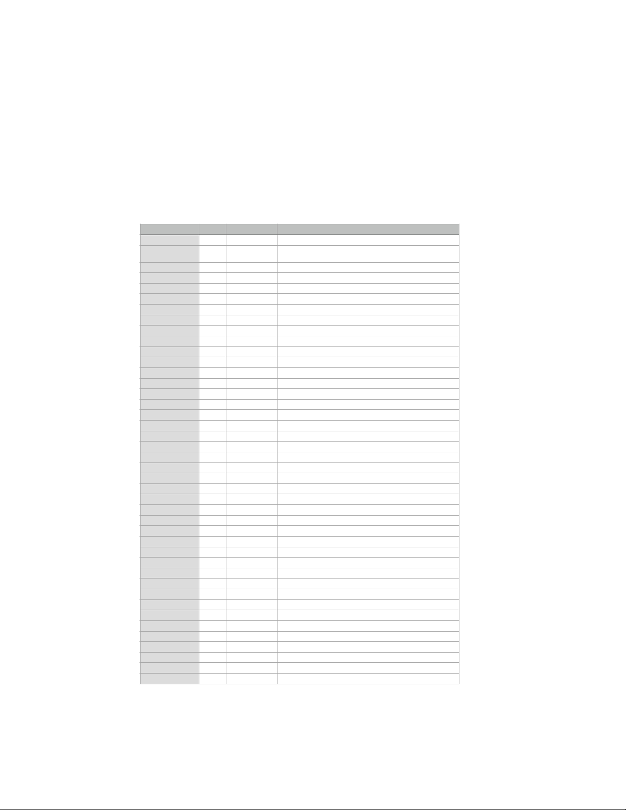
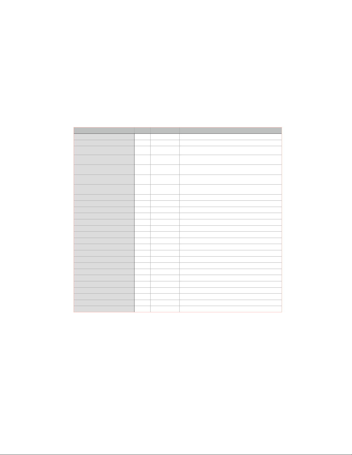
Next, install all the ICs into their sockets
in the correct locations listed on the
build tables for each respective board.
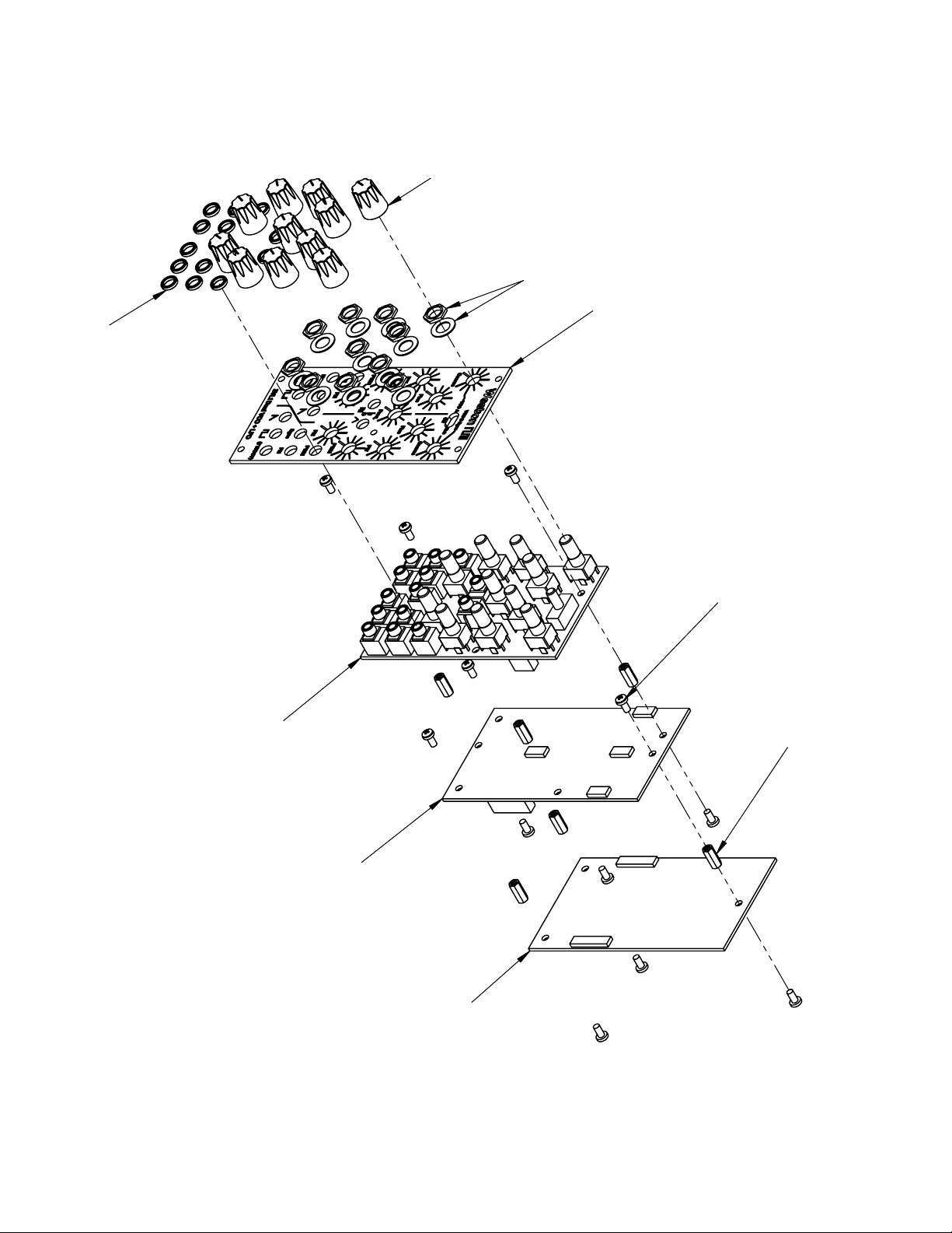
After installing the ICs, assemble the
boards together in the stack as shown in
the explode diagram on page 3. Leave
the front panel off for now.
Power the unit up and if everything went
well, you will have some waveforms and
can move on to calibration.
CALIBRATION
1) Set the controls as follows: VCO1
and VCO2 coarse and fine tune set
to achieve about 4 KHz. PW1 and
PW2 set to center. PWM1, PWM2,
FM1, & FM2 set to full CCW. LFO
rate to full CW.
2) Monitor VCO1 saw output with your
O-scope and adjust SAW1 SHAPE
trim pot to connect the halves of the
saw.
3) Monitor LFO triangle output with
your DMM or O-scope and adjust
the LFO TRI OFFSET trim pot to
center the wave about zero.
4) Monitor LFO square output with your
DMM or O-scope and adjust LFO
SQ OFFSET trim pot to center the
wave about zero.
5) Monitor VCO2 saw output with your
O-scope and adjust the SAW2
SHAPE trim pot to connect the halves
of the saw.
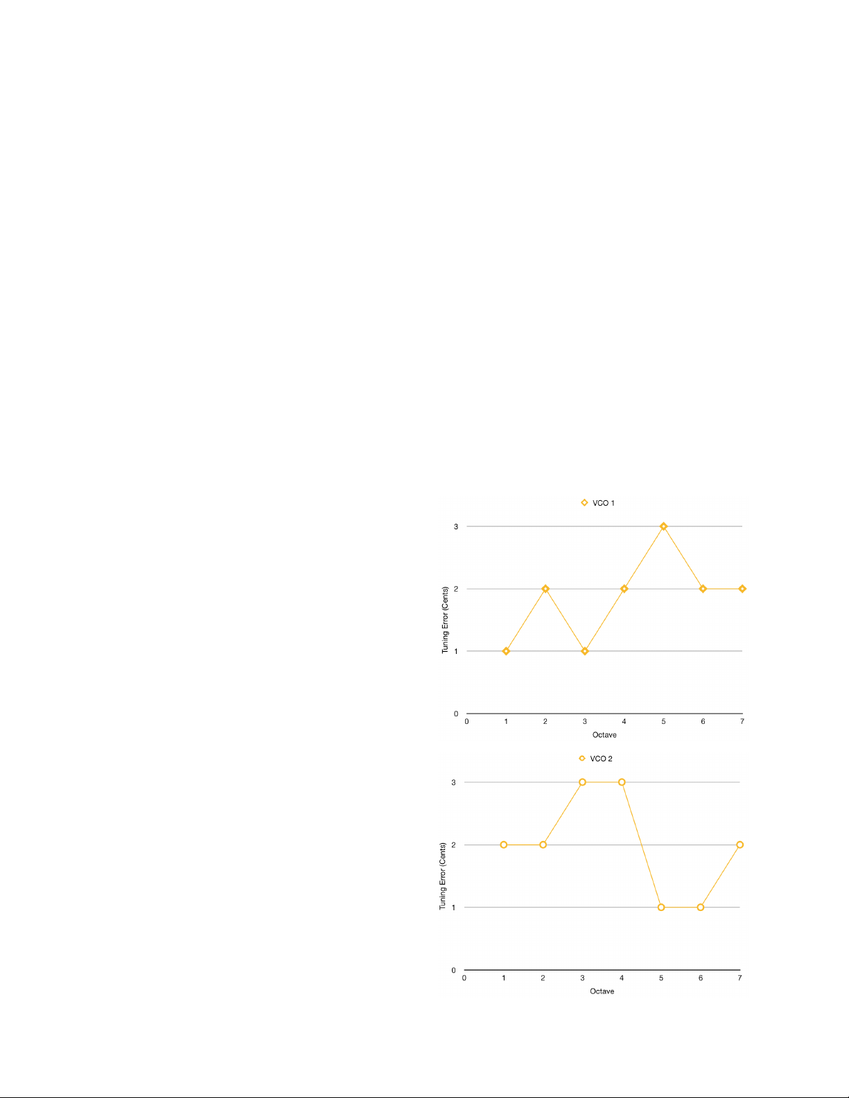
6) Plug in your 1 V/OCT CV source to
the left 1 V/OCT jack and plug the
VCO’s sawtooth wave into your
tuning app or O-scope. Hit C1 and
tune the VCO to C1 (32.7Hz). Hit
C3 and adjust VCO1 V/OCT trim to
tune to C3 (130.81Hz). Repeat this
until no further improvements can be
made. Hit C7 and adjust VCO1 HF
TRIM pot to correct any HF flatness*.
You will probably have to iterate
between correcting the HF trim and
V/Oct trim a couple of times before
you are optimally tuned. *Many
tuners and tuner apps will wig out at
high frequency. You will get best
results tuning the HF trim by using
your ear or the frequency counter
hardware on your oscilloscope.
7) Repeat (6) for VCO2.
Now install the LEDs, front panel. A note
about LEDs: It is recommended that you
use high-brightness type LEDs that will
look good with a resistor value of
4.7KOhm or higher. If the oscillating
currents for lighting the LFO LED are
© 2019 Weston Precision Audio
7

large enough, they may become ever so
slightly audible upon the pitch of not just
the 2VL1, but any other VCOs on your
Eurorack as well. The transistor circuit
and 150uF cap on PCB-C help mitigate
these ripples to a great degree, but it’s
still best to avoid high-current LEDs as
well (“Belt and suspenders”).
Be careful to not scratch the panel while
installing the jack and pot nuts and
washers!
Finally, install the knobs. The picture
below shows the recommended color
layout.
That’s it! Please enjoy your new module
and happy music making!!!
© 2019 Weston Precision Audio
8

REF (PCB Pics Finished)!
© 2019 Weston Precision Audio
9

SCHEMATICS (PCB-A)!
© 2019 Weston Precision Audio
10
1 2 3 4 5 6 7 8
1 2 3 4 5 6 7 8
A
B
C
D
E
A
B
C
D
E
Date: 2019-07-16
KiCad E.D.A. eeschema (5.0.0-3-g5ebb6b6)
Rev: ACSize: B
Id: 1/1
Title: 2VL1 PCB-A
File: 2VL1 PCB-A.sch
Sheet: /
Weston Precision Audio
12
-
13
+
14
DIODE_BIAS
15
16
U5A
LM13700
V+
10
9
U5B
LM13700
R30
51K
R28
200K
1 2
U4A
40106
VSS
7VDD 14
U4G
40106
C11
10n WIMA
-12V
V+ 11
V-
6
U5E
LM13700
-12V
+12V
C8
0.01u
GND
C9
0.01u
GND
GND
+12V
C18
0.1u
GND
3 4
U4B
40106
5 6
U4C
40106
1
-
2
+
3
U1A
TL084
+
5
-
6
7
U1B
TL084
V-
11 V+ 4
U1E
TL084
R17
8.45K
C1 1
NC2 11
E2
12
B2 13
C2 14
B1
2
E1
3
NC1
4
U3A
THAT320P14-U
GND
R12
1M
-12V
C17
33u
GND
C1
0.1u
C2
0.1u
GND
GND
-12V
+12V
R5
2K TEMPCO
GND
R7
47R
1
2
3
TP2
100R
GND
R13
820R
GND
C6
0.001u
D3
1N914
1
2
3
TP4
100K
GND
VCO1 Volts/Octave
VCO1
High Freq
Trim
R9
220K
R2
2M
R24
200K
R15
8.45K
GND
R8
1M
-12V
R3
2K TEMPCO
R4
47R
1
2
3
TP1
100R
GND
R10
820R
GND
C7
680p
D2
1N914
1
2
3
TP3
100K
GND
VCO1 Volts/Octave
VCO1
High Freq
Trim
R6
220K
R1
2M
E4
10
E3
5
B3
6
C3 7
C4 8
B4 9
U3B
THAT320P14-U
GND
9 8
U4D
40106
1
DIODE_BIAS
2+
3
-
4
5
U5C
LM13700
V+
7
8
U5D
LM13700
SYNC
PULSE GENERATOR
C3
0.01u
+12V
GND
-12V
C4
0.01u
GND
11 10
U4E
40106
13 12
U4F
40106
R33
75K
R32
47K
R31
47K
1
2
3
TP5
100K
LFO TRI OFFSET
TRIM
+12V
R34
1K
R35
1.5K
C14
22u
GND
R36
12K
GND
R39
10K
R37
47K
-12V
LFO SQ OFFSET
TRIM
R40
1K
R41
100K
LFO LED
BUFFER
C15
33u
GND
C16
33u
GND
-12V
+12V
TRI1RAW
SQ1RAW
FM1
SUM1
FM2
SUM2
SYNCIN
TRI2RAW
SQ2RAW
LFOCW
LFOCCW
LFOTRI
LFOSQ
+
10
8
-
9
U1C
TL084
+
12
-
13
14
U1D
TL084
1
10
2
3 4
5 6
7 8
9
J3
Eurorack Power
-12V
+12V
GND
GND
EURORACK POWERPOWER FILTERING
40106 POWER FILTERING
SUM1 FM1 SUM2
FM2
SYNCIN
1
10
11 12
13 14
15 16
2
3 4
5 6
7 8
9
J1
RECEPTICAL - IO 1
1
10
11 12
13 14
15 16
2
3 4
5 6
7 8
9
J2
RECEPTICAL - IO 2
LFOCW
LFOCCW
LFOTRI
LFOSQ
TRI1RAW
SQ1RAW TRI2RAW
SQ2RAW
VCO 1 CORE
VCO 2 CORE
LFO
LEDOUT
+12V
LEDOUT
1H1
M3 Mounting Hole
1H2
M3 Mounting Hole
1H3
M3 Mounting Hole
1 2
L1
100uH
1 2
L2
100uH
D4
4148
GND
GND
R22
412K
-12V
GND
R21
33K
GND
C10
10n WIMA
GND
R26
100K
R20
412K
-12V
GND
R18
33K
GND
R27
820R
R11
22K
1
2
3
Q1
2N3904
GND
R14
5.1K
+12V
1
2
3
Q2
2N3904
R16
10K
D1
4148
GND
GND
R19
5.1K
+12V
C5
0.001u
1
-
2
+
3
U2A
TL082
V-
4V+ 8
U2C
TL082
+
5
-
6
7
U2B
TL082
C12
0.01u
+12V
GND
-12V
C13
0.01u
GND
1
-
2
+
3
U6A
TL082
V-
4V+ 8
U6C
TL082
+
5
-
6
7
U6B
TL082
-12V
GND
GND
-12V
+12V
1
2
3
TP6
100K
+12V
R38
24K
-12V

SCHEMATICS (PCB-B)!
© 2019 Weston Precision Audio
11
1 2 3 4 5 6 7 8
1 2 3 4 5 6 7 8
A
B
C
D
E
A
B
C
D
E
Date: 2019-08-06
KiCad E.D.A. eeschema (5.0.0-3-g5ebb6b6)
Rev: ADSize: B
Id: 1/1
Title: 2VL1 PCB-B
File: 2VL1 PCB-B.sch
Sheet: /
Weston Precision Audio
1
-
2
+
3
U7A
TL084
+
5
-
6
7
U7B
TL084
+
10
8
-
9
U7C
TL084
R60
100K
R42
33K
R48
7.5K
1
2
3
TP7
100K
+12V R44
9.1K
TRI1 BUFFER
V-
11 V+ 4
U7E
TL084
GND
+12V
-12V
C19
0.01u
GND
C20
0.01u
GND
R68
10K
R56
10K
R57
10K
SAW1 CONVERTER
R64
100K
R74
191K
GND
R76
1K
R77
1K
R54 2K
R62 2M
R69 3K
R72
2.2K
GND
PLS1
COMPARATOR
R52
150K
GND
R46
360K
R47
100K
SAW1 SHAPE
TRIM
SQ1RAW
TRI1RAW
SAW1
TRI1
PULSE1
PWM1
PW1
+
12
-
13
14
U7D
TL084
1
-
2
+
3
U8A
TL082
+
5
-
6
7
U8B
TL082
V-
4V+ 8
U8C
TL082
C23
0.01u
GND
+12V
C24
0.01u
GND
-12V
1
-
2
+
3
U9A
TL084
+
5
-
6
7
U9B
TL084
+
10
8
-
9
U9C
TL084
R61
100K
R51
37.4K
TRI2 BUFFER
V-
11 V+ 4
U9E
TL084
GND
+12V
-12V
C21
0.01u
GND
C22
0.01u
GND
R70
10K
R58
10K
R59
10K
SAW2 CONVERTER
R66
100K
R75
191K
GND
R78
1K
R79
1K
R55 2K
R63 2M
R71 3K
R73
2.2K
GND
PLS2
COMPARATOR
R53
150K
GND
R49
360K
R50
100K
SAW2 SHAPE
TRIM
SQ2RAW
TRI2RAW
SAW2
TRI2
PULSE2
PWM2
PW2
+
12
-
13
14
U9D
TL084
1
-
2
+
3
U10A
TL082
+
5
-
6
7
U10B
TL082
V-
4V+ 8
U10C
TL082
C25
0.01u
GND
+12V
C26
0.01u
GND
-12V
1
10
11 12
13 14
15 16
2
3 4
5 6
7 8
9
J1
PINHEADER - IO 1
1
10
11 12
13 14
15 16
2
3 4
5 6
7 8
9
J2
PINHEADER - IO 2
+12V
-12V
SQ1RAW
TRI1RAW
FM1SUM1
LFOTRI
LFOSQ
SQ2RAW
TRI2RAW
FM2
SYNCIN
LFOCW
LFOCCW
SUM2
LEDOUT
1 2
3 4
5 6
7 8
J3
RECIPTICAL - IO 3
1 2
3 4
5 6
7 8
J5
RECIPTICAL - IO 5
1 2
3 4
5 6
7 8
J4
RECIPTICAL - IO 4
SAW1
TRI1PULSE1
SAW2
TRI2PULSE2
PW1
PWM1
PW2
PWM2
SUM2SUM1
FM1
FM2
SYNCIN
LFOCW
LFOCCWLEDOUT
I/O BETWEEN BOARD A & B I/O BETWEEN BOARD B & C (JACK BOARD)
1H1
M3 Mounting Hole
1H2
M3 Mounting Hole
1H3
M3 Mounting Hole
1H4
M3 Mounting Hole
1H5
M3 Mounting Hole
1H6
M3 Mounting Hole
+12V
-12V
GND
-12V
+12V
R43
100K
1
2
3
TP9
100K
+12V R45
56K
-12V
+12V
1
2
3
Q3
KSC945
1
2
3
Q4
KSC945
LFOTRI
LFOSQ
I/O BETWEEN BOARD A & B
I/O BETWEEN BOARD B & C (JACK BOARD)
GND GND
GND
R22
100K
R25
100K
GND
C27
1.5u Film
C28
1.5u Film
GND

SCHEMATICS (PCB-C)
© 2019 Weston Precision Audio
12
1 2 3 4 5 6 7 8
1 2 3 4 5 6 7 8
A
B
C
D
E
A
B
C
D
E
Date: 2019-07-16
KiCad E.D.A. eeschema (5.0.0-3-g5ebb6b6)
Rev: ACSize: B
Id: 1/1
Title: 2VL1 PCB-C
File: 2VL1 PCB-C.sch
Sheet: /
Weston Precision Audio
1
2
3J19
SAW1 OUT
SAW1 OUT
GND
1
2
3J20
TRI1 OUT
GND
TRI1 OUT
1
2
3J21
PLS1 OUT
PLS1 OUT
GND
1
2
3
J14
PWM1 IN
GND
1
2
3
RV6
100K LIN
GND
PLS1 PW
MOD AMOUNT
1
2
3
RV7
100K LIN
GND
C27
0.47u
1
2
3
J15
FM1 IN
GND
1
2
3
J12
VCO1 V/OCT IN R81
100K
GND
1
2
3
RV1
100K LIN
+12V
-12V
VCO1 COARSE
R82
164K
1
2
3
RV2
100K LIN
+12V
-12V
VCO1 FINE
R83
3.9M
1
2
3J22
SAW2 OUT
SAW2 OUT
GND
1
2
3J23
PLS2 OUT
PLS2 OUT
GND
1
2
3
J16
PWM2 IN
GND
1
2
3
RV9
100K LIN
GND
PLS2 PW
MOD AMOUNT
1
2
3
RV10
100K LIN
GND
C28
0.47u
1
2
3
J17
FM2 IN
GND
1
2
3
J13
VCO2 V/OCT IN R84
100K
GND
1
2
3
RV3
100K LIN
+12V
-12V
VCO2 COARSE
R85
164K
1
2
3
RV4
100K LIN
+12V
-12V
VCO2 FINE
R86
3.9M
1
2 3
4
SW1
SYNC SOURCE
GND
R89
10K
C29
0.47u
1
2
3
J18
SYNC IN
GND
1
2
3J24
LFO TRI OUT
GND
1
2
3J25
LFO SQ OUT
GND
D6
LED
LFO LED
SUM1
SUM2
TRI1
SYNCIN
FM1
FM2
PWM2
PWM1
1
2
3
RV5
100K LIN
+12V
-12V
PW1
1
2
3
RV8
100K LIN
+12V
-12V
PW2
SAW1
TRI1
PULSE1
SAW2
PULSE2
LFOTRI
LFOSQ
LEDOUT
D5
LED
PWR LED
R90
DEPENDS ON LED
+12V
GND
1 2
3 4
5 6
7 8
J3
PINHEADER - IO3
1 2
3 4
5 6
7 8
J5
PINHEADER - IO5
1 2
3 4
5 6
7 8
J4
PINHEADER - IO4
I/O BETWEEN BOARD B & C
PW1
PWM1
FM1
SAW1
TRI1PULSE1
SUM1
SAW2
TRI2PULSE2
SUM2 PW2
PWM2FM2
LFOCW
SYNCIN
LFOCCWLEDOUT
GND
1
2
3
RV12
1M LIN
LFO RATE
LFOCW LFOCCW
1J26
Mounting Hole
1J27
Mounting Hole
1J28
Mounting Hole
TRI2
1
J29
TRI2 TEST POINT
LFOTRI
LFOSQ
R88
100K
GND
+12V
GND
-12V
1
2
3
Q5
2N3904
GND
R91
DEPENDS ON LED
+12V
C30
150u
GND
Table of contents