Westric SW Series User manual

Manual de Instalación,
Operación y Mantenimiento

76-5023-05 Page 2 of 20

76-5023-05 Page 3 of 20
Table of Contents
Contents
Page
Table of Contents
3
Field of application
5
Model identification
5
Dimensions
7
Mounting
8
Connecting diagram
9
Wiring Diagram for Single-phase units
10
Wiring Diagram for Three-phase units
11
Operation Modes
12
General characteristics
12 –15
Terminal Block Description
16
Displaying and adjusting parameters flowchart
17
Operation Examples
18 - 20

76-5023-05 Page 4 of 20

76-5023-05 Page 5 of 20
Field of application
Westric´s SW-302sequencers are manufactured entirely by Multicontrol SA and are intended to control the
operation of two air conditioning units in telephone rooms, servers, computer centers and all those applications
where a simple but efficient and reliable control of air conditioning units is required.
Westric Sequencers are available in different versions or models:
Model Identification
S
W
-
3
X
X
X
X
X
X
X
Special Features
S= Standard
N = Economizer / Emergency Ventilation
Alarm reset
M= Manual
A= Automatic
Power supply
A= 220V - 50Hz –1ph
P = 110V - 60Hz –1ph
S = Permanent Ventilation
Operation Mode
D= Third unit Reinforces
U= Third unit Backup
NUMBER OF UNITS TO CONTROL
02 = Controls two units (1 + 1)
03 = Controls two Units (2 + 1)
Series
3 = 300 Series
Electronic Sequencer

76-5023-05 Page 6 of 20

76-5023-05 Page 7 of 20
SW-302 Dimensions

76-5023-05 Page 8 of 20
Notice: The sequencer cover should be placed as follows:
Location
The location of the sequencer in the room should be such that it is not affected by air flows that could result in
wrong temperature readings.
Suggested locations vary according to the position of the conditioning unit.
a) Both units on the same side b) One unit each side
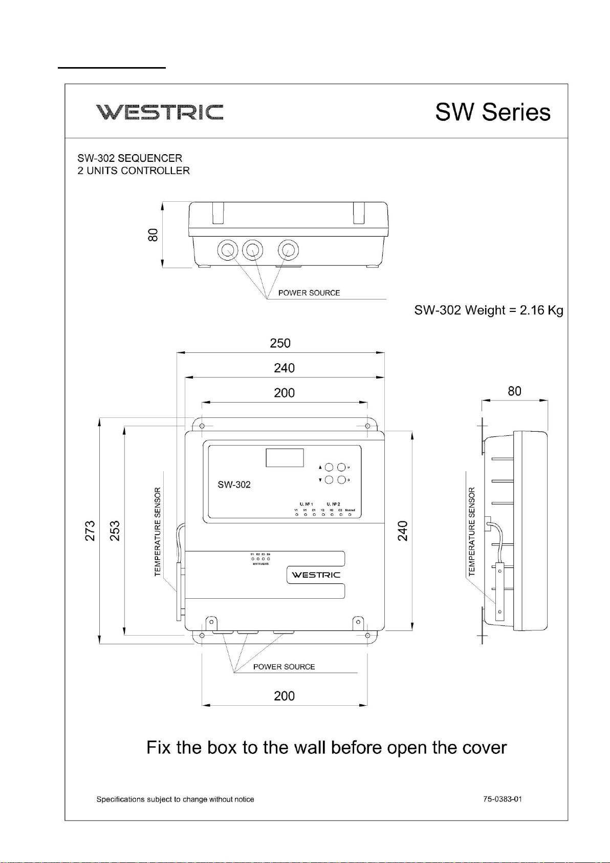
Mounting
The sequencer assembly on the wall of the room must be made through the two holes located on the outside of the
top and the two located on the bottom, without disassembling the cover, to prevent dust from entering the
controller.
SW-302 Sequencer

76-5023-05 Page 9 of 20
Connecting Diagram
Once the sequencer is fixed to the wall, proceed to connect the cables that connect it to the air conditioning unit, to
the electrical panel and to the rest of the installation parts.
It is advisable to have a 2 pole breaker switch on the electrical panel from which the sequencer will be supplied with
220VAC.
All wiring connected to the sequencer must have a minimum gauge of 1.5 mm2 (AWG 15):
1
Terminal block for connecting to fire alarm control and/or phase monitoring relay
2
Terminal block for mechanical thermostat connection
3
Dry contact terminal block for failure output
Main
Panel
Unit
1
SW-303
Power supply 220V
2 x 1.5 mm2 + Earth
Power supply according to
Unit’s model
Power supply according to
unit’s model
1
1
2
Unit
2
3

76-5023-05 Page 10 of 20

76-5023-05 Page 11 of 20

76-5023-05 Page 12 of 20
Operation Modes
D Model
When a temperature value set by the user is reached in the room, the backup unit starts as a support or
reinforcement of the head units until the temperature reach normal values. From this point onwards, only previous
working units will continue to operate.
U Model
Unlike D model, when a temperature value set by the user is reached in the room, the sequencer senses a failure
of the head unit. As a result, disconnects it and turns on the backup one. At the same time it triggers the high
temperature alarm or unit failure. In this model, both units do not work together
Digital Inputs
The sequencer has two digital inputs, E1 and E2, these are used when instantaneous cycle is desired in the event
of a unit failure, for this the unit should be provided with a safety chain and the output of a dry NC contact. The
digital inputs E1, E2 or FF have a light indication (Led), when this on indicates normal state, led off fault.
When a digital input E1 or E2 (unit failure 1, or 2) opens the sequencer cycles, turning on the unit that was in
backup, in this case the alarm for high temperature (F) that makes cycle or turn on the backup unit, is without
effect.
The E1, E2 unit digital input failure must be reset manually.
Resetting Alarms
M Model
Alarms are still on and must be reset manually even if the cause that originated them has been normalized.
A Model
The alarms are automatically reset when the cause is normalized.
Ventilation
S Model
The head unit fan are always on.
General characteristics
Operation control of two cool or cool/heat units.
Digital display indication of ambient temperature, parameter programming, and failures.
Keyboard for programming of parameters.
Programmable room temperature control
Access code for changing parameters
Hourly cycling of the unit operation programmable by keyboard and display from 1 to 7 days.
Alarm output through dry contact due to: high temperature, temperature sensor failure, power supply
anomalies, emergency stop (fire, phase failure, etc.), opening of digital inputs of equipment 1 or 2.
High temperature alarm delay programmable from 0 to 60 minutes.
Automatic start after a power failure

76-5023-05 Page 13 of 20
Light indicators when power on the following elements:
-V1: Unit 1 Evaporator Fan
-V2: Unit 2 Evaporator Fan
-R1: Unit 1 Electrical Heater
-R2: Unit 2 Electrical Heater
-C1: Unit 1 Compressor
-C2: Unit 2 Compressor
-NORMAL: Lit: No failure, Off: Failure.
System parameters
The following parameters can be displayed or programmed by the user very easily through the display and
keyboard of the sequencer.
-Ambient temperature
-Heating set point
-Cooling set point for head unit
-Cooling set point for backup unit
-High temperature alarm set point
-High temperature alarm delay
-Unit cycle time
-Access code
Emergency stop terminal block.
This terminal block can be used to interconnect the sequencer with various safety or protection devices such as
fire alarm control, phase monitoring relays, etc... When any these contacts are open, the air conditioning system
comes to a complete stop.
The Westric SW-302sequencer is delivered with a bridge in this terminal block, which must be removed if you
choose to connect it to any of the devices mentioned above.
Manual Thermostat Terminal Block (Not included in the sequencer and not required)
Westric SW-302 sequencers have a terminal block to which a mechanical room thermostat can be connected.
In the event of a possible microprocessor failure, this thermostat can be used to force both units to switch on in
order to keep the room cool.
The thermostat temperature set point must be at least one degree higher than the alarm value programmed in the
sequencer.
It should be noted that when this thermostat is actuated the timers do not, therefore it should be used for
emergency situations and only by authorized personnel.
For connection to the terminal block, the lower and upper cover of the sequencer must be removed.
Terminal block for unit stop.
It has two terminals one for each unit, these digital inputs are for the case that the unit has a failure digital output,
when it opens the sequencer instantly cycles to the backup unitt and stop the one that was working. The reset of
this failure is manual.

76-5023-05 Page 14 of 20
Access code to access parameter modification (password).
The programming of parameters of the system is protected by an access code or password, factory set is 000. To
enter the code press the arrows, this increases or decreases the unit, pressing D increases the ten. If an incorrect
code is entered three times in a row, the real key is blocked for one minute.
Compressor restart timing
The SW-302sequencers have a compressor restart timer that prevents a compressor from restarting until three
minutes have elapsed.
Power source connect or reconnect timer delay
Each time the sequencer is connected to the power line or power is returned after a power outage, a three-minute
timer is triggered that disables compressor startup during that period. If the system detects temperature to turn on
the two compressors, after three minutes they starts with five seconds delayed between them.
Terminals for connecting the sequencer and the units.
Input terminal block for power supply of the sequencer 220V - 50Hz (N+L+E)
Non Volatile Memory
The SW-302sequencer has a non-volatile memory in which the following information is stored in the event of an
indefinite power failure:
- All system parameters and set points
- What unit whas working as head at the time of the power outage.
- Number of operating hours of head units up to the time of power failure
This ensures uniform wear of the machines even in areas with frequent power outages.
When the power is restored, the sequencer keeps the programming of parameters and set points, turns on the unitt
that was working at the time of the power outage and keeps it working until completing the number of hours
remaining for the cycle. After three minutes from the power source backs, the compressor is enabled.
Manual cycle
By entering a code through the keypad, the sequencer allows you to change the head unit to the backup unit. This
function has been incorporated to allow the manual rotation of the units and to eases the maintenance and repair of
the units.
Alarm display
The SW-302Sequencers indicates triggering of the alarms by the elements indicated in each case below:
High Temperature Alarm
The display shows ALT and the room temperature alternately.
The sequencer beeps
NORMAL LED goes out
The failure dry contact closes

76-5023-05 Page 15 of 20
Temperature sensor failure alarm
The display flashes showing STE
The sequencer beeps
NORMAL LED goes out
All unit control outputs opens
The failure dry contact closes
Emergency stop alarm
The display flashes showing FF
The sequencer beeps
NORMAL LED goes out
All unit control outputs opens
The failure dry contact closes
Power supply failure alarm
The display flashes showing BTE
The sequencer beeps
NORMAL LED goes out
All unit control outputs opens
The failure dry contact closes
Digital input alarm
The display flashes showing FE1 or FE2 (unit 1 or 2).
The sequencer beeps
NORMAL LED goes out
All unit control outputs opens
The failure dry contact closes

76-5023-05 Page 16 of 20
Terminal Blocks
Terminal Block
block
Terminal
Description
Digital Inputs
Com
Digital inputs common
E1
Connect to the NC failure terminals of unit #1 (if available).
Factory set bridged
E2
Connect to the NC failure terminals of unit #2 (if available).
Factory set bridged
Fire, FF
Connect to the Fire Alarm Control NC terminals, or to the Phase Monitoring
Relay auxiliary NC terminals.
Factory set bridged
Unit 1
Unit 2
COM
Outputs common
V
Evaporator fan
R
Electrical Heater
C
Compressor
Failures
NA
Remote alarm failure output - NO
LM
Remote alarm failure - Common
NC
Remote alarm failure output - NC
Ext Thermostat
External thermostat
Connect to a mechanical room thermostat for emergency operation
(Optional and not indispensable for the operation of the sequencer)
External thermostat
Power Source
T
Earth
N
220VAC 50Hz power supply to the sequencer
L1
Keyboard
Key
Function
Forward and back screens, to increase or to diminish the value of the parameters and to
enter codes.
D
Displays the content of a parameter, in access code sum of 10
G
Saves the new value assigned to a parameter. Pressing it a second time allows you to exit
the setting screens.

76-5023-05 Page 17 of 20
Displaying and adjusting parameters flowchart
Parameter
Description
Range
Minimum
Maximum
Factory
t2
Cycling time in days
1 day
7 days
1 day
t1
High temperature alarm delay
0 min
60 min
0 min
F
High temperature alarm set point
C2 + 1ºC
31º.
31ºC
29ºC
C2
Backup unit compressor start setpoint
(2nd refrigeration stage)
C1 + 1ºC
30ºC
25ºC
C1
Head unit compressor start setpoint
(1st refrigeration stage)
21ºC
29ºC
23ºC
r
Heating set point
10ºC
C1-1ºC
14ºC
Cod
Access code for parameter change
000
255
000

76-5023-05 Page 18 of 20
Example of parameter display
Let us suppose that we want to visualize the content of parameter F
Starting from the ambient temperature, press the keys indicated below:
23.5
F
D
30.0
D
F
Press the key
Several times until you return to the room temperature display
Example of parameter adjustment:
Suppose we want to adjust the content of parameters t1 and F
Starting from the ambient temperature, press the keys indicated below:
The access code is increased by ten by pressing D
23.5
Cod
D
000
Enter access code
XXX
G
r
t1
D
000
Change parameter
0XX
G
t1
F
D
30
Change parameter
0XX
G
F
G
Double beep confirms the recording of
parameters
23.5
Indicator lights
Indicator
Description
Color
V1
On indicates start of the unit 1 evaporator fan
Yellow
R1
On indicates start of the unit 1 electrical heater
Yellow
C1
On indicates start of the unit 1 compressor
Yellow
V2
On indicates start of the unit 2 evaporator fan
Yellow
R2
On indicates start of the unit 2 electrical heater
Yellow
C2
On indicates start of the unit 2 compressor
Yellow
NORMAL
Power on indicates no alarms
Green

76-5023-05 Page 19 of 20
Built-in fixed timers
Timer function
Time
Delay in compressors start due to power failure
3 min
Compressor restart delay due to temperature change, set point, etc.
3 min
Phase shifted between compressors
5 sec
Return to the temperature display from an inactive display
1 min
Disabling the input of the access code due to repeated erroneous entry (3 times)
1 min
Alarm Identification
Message on the Display
Identification
Action
ALT
High Temperature Alarm
The display shows ALT and the room
temperature alternately.
The sequencer beeps
NORMAL LED goes out
The failure dry contact closes
STE
Temperature Sensor Failure Alarm
The display flashes showing STE
The sequencer beeps
NORMAL LED goes out
All unit control outputs opens
The failure dry contact closes
BTE
Power Supply Failure Alarm
(Low voltage)
The display flashes showing BTE
The sequencer beeps
NORMAL LED goes out
All unit control outputs opens
The failure dry contact closes
FE1,FE2
Unit Failure stop alarm (Digital
input)
The display flashes showing FE1,
FE2 (unit 1 or 2).
The sequencer beeps
NORMAL LED goes out
All unit control outputs opens
The failure dry contact closes
FF
Emergency Stop Alarm
(Fire, phase failure, etc.)
The display flashes showing FF
The sequencer beeps
NORMAL LED goes out
All unit control outputs opens
The failure dry contact closes

76-5023-05 Page 20 of 20
Alarm reset
To reset the beeping alarm signal press G
To reset the display and the output of dry contacts, press D on M models sequencers, provided that the problems
that caused the fault have been normalised, otherwise the alarm will be triggered again.
In A models, the display and dry contact output are automatically reset when the causes that generated the fault
disappear.
Manual cycle
In order to facilitate maintenance work and testing of the units, it is possible to manually cycle the units in the
following way:
Press from the room temperature display:
D
G
Customer service
If you have any questions regarding the installation, programming or use of this product, please contact Westric´s
Electronic Department at +5411-4715-2522.
This manual suits for next models
1
Table of contents