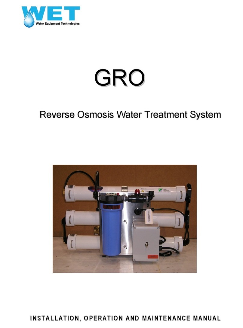
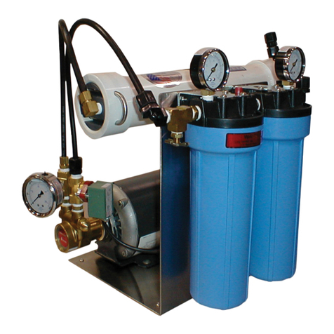
WET ES Series User manual

E
ES
S
S
Se
er
ri
ie
es
s
R
Re
ev
ve
er
rs
se
e
O
Os
sm
mo
os
si
is
s
W
Wa
at
te
er
r
T
Tr
re
ea
at
tm
me
en
nt
t
S
Sy
ys
st
te
em
m
I
IN
NS
ST
TA
AL
LL
LA
AT
TI
IO
ON
N,
,
O
OP
PE
ER
RA
AT
TI
IO
ON
N
A
AN
ND
D
M
MA
AI
IN
NT
TE
EN
NA
AN
NC
CE
E
M
MA
AN
NU
UA
AL
L

2
I
IM
MP
PO
OR
RT
TA
AN
NT
T
U
US
SE
ER
R
I
IN
NF
FO
OR
RM
MA
AT
TI
IO
ON
N
PLEASE DO NOT DISCARD
THIS MANUAL CONTAINS IMPORTANT INFORMATION WHICH
SPECIFICALLY APPLIES TO THIS UNIT. THIS INFORMATION MAY BE
NEEDED AS REFERENCE DURING ANY FUTURE SERVICING OF THE
SYSTEM.
D
DI
IS
SC
CL
LA
AI
IM
ME
ER
R
A
AN
ND
D
L
LI
IM
MI
IT
TA
AT
TI
IO
ON
NS
S
This manual discloses proprietary information of WET. This information is provided for the purpose of operating
and maintaining its RO systems, and may not be used for any other purpose.
It is recommended that this manual be read and understood before performing installation, operation, and
maintenance of the RO system. The equipment warranty may be voided if instructions are not followed correctly.
The information provided may not cover all possible variations of detail in relation to equipment use. Please
contact the WET Service Department for any technical questions that are not specifically answered in this
manual.
The Seller reserves the right to make enhancements or changes that may not be included in the manual.
Therefore, it is understood that the material presented here is subject to change without notice and is for
informational purposes only.
This manual is believed to be complete and accurate at the time of publication. However, WET assumes no
responsibility for the technical content of the manufacturer literature. Due to the inability to verify all vendor-
provided materials, WET assumes no responsibility for any errors and shall not be liable for damages in
connection with the use of this manual.
© Copyright 2006 WET. All rights reserved.
I
IN
NI
IT
TI
IA
AL
L
I
IN
NS
SP
PE
EC
CT
TI
IO
ON
N
A
AN
ND
D
H
HA
AN
ND
DL
LI
IN
NG
G
On receipt of the RO unit, note any damage on appropriate shipping documents. File damage
claims with carrier immediately (not WET).
RO MODEL______________________________
INSTALLED BY___________________________
TELEPHONE_____________________________
INITIAL STARTUP DATE___________________
W
Wa
at
te
er
r
E
Eq
qu
ui
ip
pm
me
en
nt
t
T
Te
ec
ch
hn
no
ol
lo
og
gi
ie
es
s
1
10
06
66
61
1
N
Ne
ew
wk
ki
ir
rk
k
S
St
tr
re
ee
et
t
D
Da
al
ll
la
as
s,
,
T
TX
X
7
75
52
22
20
0
T
Te
el
l:
:
1
1-
-8
80
00
0-
-7
78
86
6-
-7
74
48
80
0
T
Te
el
l:
:
1
1-
-5
56
61
1-
-6
68
84
4-
-6
63
30
00
0
F
Fa
ax
x:
:
1
1-
-5
56
61
1-
-4
47
71
1-
-0
06
62
29
9
h
ht
tt
tp
p:
:/
//
/w
ww
ww
w.
.w
we
et
tp
pu
ur
re
ew
wa
at
te
er
r.
.c
co
om
m

3

4
Safety Check Item
Don’t Do This
Special Attention
SAFETY NOTES – READ AND UNDERSTAND BEFORE PROCEEDING
Safety Check Item
Don’t Do This
Special Attention
WARNING
√High Voltage Electricity √Spinning Parts
√High Pressure Components √Pressurized Water
√Noise
Failure to follow good safety practices and the instructions included in this manual
may result in damage to the unit, its surroundings, personal injury or death.
Please take all possible precautions when working on or around this unit.
Pressure
Reverse Osmosis units operate by forcing water at high pressure against a semi-permeable membrane. The
higher the TDS (Total Dissolved Solids) of the feedwater, the higher the pressure required to produce
acceptable amounts of purified water. Fresh water typically requires up to 150 psig to suitably overcome
osmotic pressure. Even a small leak at elevated pressures can be dangerous.
Electricity
Electricity and water DO NOT MIX. Every effort is made to insure that the electrical equipment on our systems
is resistant to water intrusion. Once installed, the system is subject to many factors beyond our control.
•The reject water of this RO unit is a concentrated solution with high electrical conductivity. Spills should be
immediately cleaned. Leaks of any kind should be repaired as soon as possible.
•Check all electrical components on a regular basis to insure that water-resistant seals are still in place and
functional.
•DO NOT DRILL HOLES IN THE TOP SURFACE OF ANY ELECTRICAL BOXES.
Chemicals
•Exposure to the highly concentrated reject water, especially at the high pressures of an operating RO unit,
can cause injury or permanent damage to the eyes, skin, and mucous membranes.
•Exposure to the chemicals used in cleaning, disinfection, and preservation is dangerous and may cause
permanent damage.
•Test all hoses and connections before using any cleaning system to clean or preserve the membranes. Do
NOT allow worn hoses or fittings to be used.
•Avoid contact with chemicals by wearing eye and skin protection equipment. Avoid breathing chemical
fumes.

Table of Contents
Section Page
System Description .................................................................................................................................5
Installation ...............................................................................................................................................8
Initial Startup .........................................................................................................................................10
Operation ..............................................................................................................................................11
System Maintenance.............................................................................................................................13
Cleaning RO Membranes......................................................................................................................16
Disinfection............................................................................................................................................21
Preservation ..........................................................................................................................................22
Troubleshooting ....................................................................................................................................23
Drawings
Unit P&I Diagram
Electrical Schematic
RO Unit Layout
Appendix
ES Series Specifications
Limited Warranty
Warranty Service Policy
Daily Operator Log Sheet
Cleaning Log
RO Maintenance Schedule

5
System Description
Theory of Operation
Feed water is supplied to the RO unit through a inlet valve. Next, the feed water passes through a
pre-filter for removal of suspended particles 5 microns or larger.
The filtered water enters a high-pressure pump where the water pressure is increased to RO
operating levels and is directed into the 1st stage RO membrane assembly. Inside the membrane
assembly, a portion of the feed water, referred to as product or permeate, passes through a
membrane barrier that rejects suspended and dissolved solids. The remaining portion of feed
water, referred to as reject or concentrate, carries concentrated contaminants out of the membrane
assembly. This reject water is sent to the 2nd stage RO membrane assembly, which extracts
additional product water.
The reject water, upon leaving the 2nd stage RO membrane assembly, is regulated by a Reject
valve, and is monitored by a flow indicator, before leaving the system to waste.
The combined product water from both the first and second stage RO membranes is monitored by
a conductivity sensor and analytical instrument to determine the Total Dissolved Solids content of
the product water.
Recovery, an important operating parameter, is the ratio of the product water to the feed water
flow. See the System Specifications section of this manual for details.
The ES Series of RO systems will produce high quality water from either municipal or well
water supplies. The reverse osmosis process uses a semi-permeable spiral wound membrane
to separate and remove dissolved solids, organics, pyrogens, submicron colloidal matter, and
bacteria from water. The feed water is pressurized to approximately 130 PSI forcing the water
molecules through the minute pores as purified water. Impurities in the water are generally too
large to pass through the pores and they are concentrated in the "reject" stream and flushed to
the drain. The RO membranes are capable of removing 90 - 99% of Total Dissolved Solids
(TDS), and up to 99% of organics, pyrogens and bacteria that may be in the feed water.

6
ES Series Layout

7
ES Series Standard Features
The ES Series of RO Systems is designed for light commercial use. Simplicity of design and the
use of industry standard components provide for reliable operation and easy serviceability. With
over 20 years experience in design and manufacture of water treatment solutions, the ES Series
RO System has provided dependable, cost-efficient water production to thousands of customers
and end users around the world.
ES Series Standard Features
• Thin Film Composite Membranes
• Industrial Painted Frames
• Stainless Steel Pump
• Heavy Duty FRP Pressure Vessels
• 5 Micron Sediment Pre-filter
• Manual Feed Water Shutoff Valve
• Product Water Check Valve
• Panel Mounted Instruments & Lights
• Automatic Inlet Valve
• Low Pressure Pump Shutoff
• Product, Reject & Recirculation Flow Indicators
• Feed & Product Water Sample Ports
• Poly Tubing & Fittings on Product Line
• Heavy Duty Concentrate & recirculation Control Valve
• Pretreatment Lockout
• Pre and Post Flush
• Factory Performance Tested

8
Recommended Operating Limits
The model number of your unit designates the system's daily production capacity. For example, a
model ES-600 will produce 600 gallons of water per day plus or minus 15%. This production is
based on a feed water temperature of 77 degrees F (25 degrees C), Total Dissolved Solids of
1000 ppm or less, turbidity of less than 1 NTU and a Silt Density Index (SDI) of less than 5.
Higher or lower water temperature will increase or decrease the product water output. Higher
TDS levels will decrease output production.
Complete equipment and operating specifications for the ES Series RO systems is included in the
Appendix.
Recommended RO Operating Limits
Water Pressure 40 to 90 PSI (275 to 620 kPa)
Total Dissolved Solids (TDS) 1000 PPM (mg/l)
Temperature 40° to 85° F (4.4° to 29.4° C)
pH
2 to 11
Hardness 51 PPM (3 grains per gallon)
Iron
0.2 PPM (mg/l)
Chlorine 0.0 PPM (zero)
Turbidity
1 NTU max.
SDI 5 max.

9
Installation
RO Unit Piping
Chlorine MUST be removed from the feedwater if present. Chlorine will
damage thin film composite membranes and void the warranty. If
activated carbon is used to remove chlorine, the carbon MUST be rinsed
to drain before the RO unit is operated.
RO Installation Requirements
1. The RO system and its components should be installed indoors whenever possible.
2. The system must be protected from freezing at all times. If shipped to warm climate (ambient
over 70°F) inspect for bacteria.
3. The site should allow for adequate ventilation in order to relieve heat buildup which can cause
weakening of fitting and plumbing connections.
4. The feed pressure should be at least 20 psi and no greater than 90 psi.
5. All pumps must be aligned to manufacturer’s specifications prior to initial pump startup.
6. The RO system will produce a sound level of approximately 80-90 decibels. The system should
be installed in a location where these sound levels will not be an issue.
7. Suitable drainage capable of removing the free discharge of the supply source. Drain
connections must be suitable for the disposal of concentrated saline, acid/alkaline chemicals, and
membrane preservatives or disinfectants.
Piping Assembly
Connect the feed, product, and reject lines to the RO unit using non-corrosive hose, pipe, or tubing.
Tubing for the product and reject connections are supplied with the unit.
The feed connection is located near the pre-filter cartridge housing. The product and reject
connections are located behind the instrument panel at the flowmeter connection. Refer to the
system layout drawings in the Appendix of this manual for the proper connection sizes.
For drain connections the use of an air gap to prevent possible back flow into the RO
unit is recommended.

10
Electrical
Electrical Assembly
The RO controls are contained in an RO Control Panel mounted on the front of the skid. The Control
Panel houses the relays, timers, and pilot devices (lights and selector switches) required for operation
of the RO system.
Use copper conductor for grounding equal to the circuit conductors supplying power to
this system.
Electrical installation should be done by a qualified electrician to avoid personal and/or
possible damage to the RO unit.
Verify the correct voltage for your system by referring to the “MANFACTURED BY” name plate
and NOT the motor plate.
Plug in the RO system using the 3-prong plug in a standard 115 VAC outlet or 220 VAC outlet as
required. If the RO unit is equipped with a 3-phase motor, connect 3-phase power to the motor
starter and check for proper rotation.
Terminals #1 and #5 (see electrical diagram provided in the Appendix) are provided for automatic
on-off operation with a product tank level switch for non-pressurized systems or a pressure switch
for pressurized systems. For manual operation, place a jumper between terminals #1 & #5.
Do NOT run injector tubing and electrical wiring in the
same conduit.

11
Initial Startup
Procedure
Successful long-term performance of the RO system depends on proper operation and
maintenance of the system. Proper startup is essential to prepare the membranes for operating
service and to prevent membrane damage due to overfeeding or hydraulic shock. Following the
proper startup sequence also helps ensure that system operating parameters conform to design
specifications so that system water quality and productivity goals can be achieved.
It is recommended to perform a full feed water analysis immediately
prior to startup to establish initial feed water contamination levels.
Initial Startup Procedure
1. Disconnect the product water line at the service connection (not flowmeter). Direct the
line to a drain to discard the product water during the first hour of operation.
This RO system is shipped with a disinfectant compound (sodium metabisulfite)
in the membranes. Before using any water from the RO, operate the system for
ONE HOUR with all water going to drain.
2. Start the feedwater supply.
3. Open the reject valve completely.
4. Start the RO system using the control power toggle switch on the Control Panel.
5. Adjust the reject valve until the flows match those indicated in the ES Series System
Specifications (see Appendix). If the unit is equipped with a recirculation loop, the
recirculation valve may require adjustment also.
6. Operate the RO for ONE HOUR with all product water going to drain.
7. Shut down the RO using the toggle switch. Reconnect the product water line. The RO is
ready for normal operation.
Do not exceed 190 PSI pump pressure (Models ES-450 and ES-600) and 225 PSI on
Models ES-1000 to ES-9000.

12
Operation
Startup
1. With feedwater supply being delivered to the RO system, open the Reject valve, then
start the system using the On-Off switch.
2. Adjust the reject valve until the product flow reaches the proper flow rate. (See System
Specifications) As the valve is closing the product flow will increase, the reject flow will
fall, and the pump pressure will rise.
DO NOT exceed the recommended product flow rate or fall below the
minimum reject flow rate shown in the System Specifications for your unit or
membrane fouling could occur very rapidly.
3. After the proper flows have been set and an adequate amount of water has been
pumped to drain, record all flows, pressures, TDS levels and water temperature (See
RO Daily Log Sheet in Appendix). This initial start-up information is very important when
determining the system’s performance over time. For accurate TDS readings, let the RO
system run for at least 15 minutes.
Shutdown
The ES system can be turned off manually with the On-Off switch.
In normal operation, the unit will automatically shut off when the storage tank is full or at a
desired pressure. After any normal shutdown, the RO system will enter a short post-flush cycle
(see next page for details)
To prevent biological growth during system shutdowns (one week or longer) the
membranes must be immersed in a preservative solution (Item #753).
If sanitization is required, the system must be in use for at least six hours before
formaldehyde can be used. If the membranes are exposed to formaldehyde before being
in use for this period of time, severe damage will result. Other disinfecting solutions such
as hydrogen peroxide can be used. For further information, contact your local
representative.

13
Pre and Post-Flush
Shutdown of the RO unit by loss of mains power prevents post-
flush of the system and may cause fouling or corrosion. If an
emergency shutdown is necessary, restart the system as soon
as practical.
The pre-flush floods the membranes and the RO pump suction, removing trapped air in the
lines. The RO pump will start and the automatic flush valve will close at the end of the pre-
flush cycle.
The post-flush washes reject concentrate from the entire system to prevent mineral deposits,
scaling or sludge buildup. Post-flush prolongs the life of the membranes, valves, fittings and
other components of the system.
When the RO is shut down normally, using the toggle switch (or by an optional product tank
pressure switch or level device), the RO pump will stop, then the Inlet valve will open for a
predetermined time to allow filtered feedwater to flush the system at low flow and pressure,
before the post-flush cycle times out and the valve closes.
If an emergency shutdown is required, restart the system as soon as practical. At minimum,
allow a pre and post-flush event before the system is shut off for any length of time (This can
be done by starting the system for a brief period to allow the pre-flush cycle to complete, then
immediately powering off the system, causing a post-flush cycle to occur.)

14
System Maintenance
Overview
A daily operators log, along with RO system maintenance and cleaning schedules, can be
found in the rear of this manual. Make copies for the operators and send the completed copies
to XYLEM to validate the warranty.
Follow these basic guidelines to minimize unplanned downtime
Complete Log Sheets regularly. Add data as needed.
Review the data periodically. Look for unusual readings and trends.
Be familiar with your equipment. Periodically inspect all components.
Use sight, sound, smell and touch to discover unusual conditions.
Component Preventive Maintenance Activity Remarks
RO Membranes
Clean the membranes when the
normalized water output rate drops by
10%, salt content in the product water
rises noticeably, or the differential
pressure increases by 15% from the
reference conditions.
See Cleaning section and OEM literature for
details.
Pumps
Check pump clamp
ES-450, ES-600 only (Monthly)
Check shaft coupling setscrew
ES-1000 through ES-9000 (Monthly)
Pre-Filters
Check ∆P. If ∆P drops, open filter
housing and inspect cartridges for
damage / blockage. If the difference
between the filter inlet and outlet
pressures (∆p) reaches 10 PSI,
replace the filters.
Replace the cartridges with 5 micron rated
filters. Replace the cartridges 4 times per year,
regardless of pressure drops, to minimize
bacterial growth.
Pressure
Vessels
Check the pressure vessel head
assemblies for leakage.
Replace the pressure vessel head seals if
leaking occurs.
Instruments Wipedown, visual inspection, leak
check, zero and span, cleaning
Maintain data history log for each instrument.
Keep consumables and spares in stock.

15
Major Components
Remove pressure and shut down the RO system attempting any
service or repair on high pressure components.
Reverse Osmosis Membranes
Mineral scale, biological matter, colloidal particles and organic constituents can cause
membrane fouling during normal operation. Build-up on the membranes causes loss in water
output, salt rejection, or both. Clean the membranes when the normalized water output rate
drops by 10%, salt content in the product water rises noticeably, or the differential pressure
increases by 15% from the reference conditions. (Reference conditions refer to the flow rate
and differential pressures established during the first 24 to 48 hours of operation.)
Water output drops as feed water temperatures decrease. Malfunction in the pre-treatment,
the pressure control or pump can cause a drop in the feed water pressure or flow, the product
water output or increase in salt passage. Consider these situations when problems are
observed. Membranes may not require cleaning. Refer to the Cleaning section of this manual
or the Filmtec OEM Literature for details.
RO Pump
Follow the recommended interval for the duty cycle of your specific RO unit. Lubricate pumps
and motors with manufacturer recommended lubricants for longest life. Environmental and
operational conditions will contribute to the minimum required lubrication intervals.
Ensure that the set screw is tight and the coupling is not loose. If the set
screw is allowed to become loose, damage to the shaft and coupling
could occur.

16
5 Micron Pre-filter
The 5-micron rated cartridge filters remove particulate matter from the feed water harmful to
the RO pump and membranes. When the pressure difference between the filter inlet and outlet
reaches 10 PSID, replace the filter cartridges. Differential pressure across filters increases
with time. When the ifferential pressure drops, open the filter housing and inspect the
cartridges for damage. Replace the cartridges (4) four times per year, regardless of pressure
drops, to minimize bacterial growth.
Extreme care must be taken not to allow debris to enter the RO feed.
Adequate pre-filtration is recommended to avoid damage to the RO
membrane elements.
Activated Carbon Filter
(If installed) An activated carbon filter may be included with the ES series RO system to remove
chlorine that can damage the membranes. The carbon filter must be rinsed and backwashed
before initial startup and at regular intervals to ensure that loose carbon fines are flushed to
drain.
Carbon filters lose efficiency over time and require periodic testing for chlorine breakthrough.
Activated carbon should be REPLACED every 4 months OR SOONER to prevent breakthrough.
A chlorine test kit (available from your dealer) is used to check for chlorine as follows:
With the unit running, draw a sample from the pre-filter drain valve. Test the sample for free
chlorine residual. If any chlorine is detected, replace the activated carbon immediately.
Do NOT replace the 5 micron pleated cartridge with an activated carbon cartridge.
An activated carbon cartridge does not have enough surface area to effectively
remove all of the chlorine in the feedwater. Severe pressure drops may also occur,
causing the unit to continuously cycle on and off and damage the pump.
Pressure Vessels
The pressure vessels need no maintenance other than periodic inspection and wipe down with
a damp cloth and mild dish soap solution. All connections should be checked for leakage. No
leakage should be tolerated which might cause corrosion of fittings.
Conductivity Monitors (TDS), Flow Meters, Pressure Gauges
No instrument or sensor lasts forever and any wide variations in a reading over a short interval should
be investigated. Connections should be checked and the sensor reading tested against a sample
taken from an appropriate system sample port. Calibration charts for each instrument should be
maintained and each unit tested with fresh standard solutions immediately prior to use. Detailed
maintenance and operating procedures are located in the OEM literature included with this manual.

17
Cleaning RO Membranes
Overview
In normal operation, the membranes in the RO system pressure vessel(s) become fouled by mineral
scale, biological matter, colloidal particles and insoluble organic constituents. Deposit build up on the
membrane surfaces can cause loss of water output, loss of salt rejection, or both.
Membrane elements should be cleaned whenever the normalized water output rate drops by 10%, or
the differential pressure (∆P) increases by 15% from the initial startup reference conditions. (The
need for cleaning more than once per month may indicate that pre-treatment is inadequate.)
Acid and alkaline cleaners are the standard cleaning chemicals. Use acid cleaners to remove
inorganic precipitates including iron, and alkaline cleaners to remove organic fouling including
biological matter. Use reverse osmosis permeate water for mixing cleaning solutions whenever
available. If permeate water is not available, use only clean, chlorine-free water for cleaning. Rinse
the RO unit thoroughly of one chemical before introducing another.
When working with chemicals, follow the accepted safety practices. Water Equipment Technologies
supplied chemicals are generally mixed with 1 pound of powdered cleaner to each 15 US gallons of
clean water. For severe fouling, this concentration can be increased to as much as 1 pound per 10
US gallons of water, but this should be avoided as harsh cleaning can reduce the useful life of the
membranes.
RO membranes should be cleaned whenever:
Normalized water output rate drops by 10%,
Salt content in the water rises noticeably (10%)
Differential pressure (
∆
P) increases by 15% from the flow rate and
∆
P
established at initial startup.
Failure to observe this cleaning schedule will cause premature fouling and
reduced service life from the membranes.

18
The pH levels for acid and alkaline cleaning depend on water temperature. It is NOT recommended
to use a cleaning temperature below 15° C because of the very slow chemical kinetics at low
temperatures. When difficult organic fouling problems exist, alkaline cleaning procedures will be
more effective when performed at elevated temperatures. Solutions maintained at 45 - 50 degrees C
at a maximum pH of 10, 35 degrees C at a maximum pH of 11, or 30 degrees C at a maximum pH of
12 are recommended.
Several conditions can cause a reduction in the water quality and/or water production. The following
items should be checked before considering cleaning.
1. Temperature change
Water temperature will affect production rates. Lower water temperature will result in LESS
water passing through the membrane. Higher water temperature will result in MORE water
passing through the membrane. As a rule, at a given pressure and TDS level, for each one
degree change in water temperature the change in water production is approximately 2%.
Thus, if the water temperature is 20 degrees C, the amount of water produced will be 10%
less than at 25 degrees C.
2. TDS level increase
As the TDS (Total Dissolved Solids) level climbs, the amount of water passing through the
membrane decreases. If the TDS level has climbed since the time of installation the unit will
produce less water. Check the TDS level of the feed water and compare it with the TDS level
at the time of installation. If the TDS levels have climbed, the rejection rate will have to be
increased to reduce the TDS level build-up within the membrane.
3. Pre-filters plugged
A dirty pre-filter can reduce the amount of water and the pressure going to the RO unit. If a 5
micron filter cartridge appears dirty, it should be cleaned or replaced. On extremely dirty
water, a larger pre-filter may be needed. When cleaning the pre-filter, check its condition. If
signs of wear appear, replace it immediately.
4. Change in flow rates or water pressure change
Check the product and reject flow rates to determine any change from normal conditions.
Adjust the flows and pressures if necessary to maintain the proper settings.
Follow the unit’s normal direction of flow during cleaning. Refer to the OEM literature in this manual
for more information about cleaning RO membranes.
This unit was shipped without a cleaning system. For purposes of illustration, a
simplified cleaning diagram and the cleaning instructions in this section reference the
typical RO membrane cleaning system available through your XYLEM representative.

19
Procedure
Step 1 Mix the Cleaning Chemicals
Remove the plug and connect a line to the product connection. Connect the other end to the Product
Return connection on the cleaning tank.
Fill the cleaning tank with non-chlorinated product water.
Add the appropriate amounts of chemicals (1 lb. to 15 gal of H2O) of the appropriate chemical (i.e.
acid/alkaline) into the cleaning tank. Refer to
the labels on the chemical containers for
instructions. Mix the solution, checking the pH,
until all chemicals are dissolved and well
mixed before circulating the solution to the
elements.
Close the Reject valve completely.
Step 2 Low Flow Pumping
Connect a line to the feed cleaning connection. Connect the other end to the cleaning system feed
connection.
Remove the plug/cap and connect a line to the reject cleaning connection on the reject header and
back to the reject return connection on the cleaning tank.
Close the feed cleaning valve halfway (50% open) and start the cleaning system pump. This will
pump the cleaning solution through the membranes at a low flow and low pressure to displace the
process water. Low flow and pressure (between 4 to 5 GPM for each pressure vessel) minimizes
redisposition of dirt on the membranes.
Verify the flow at the cleaning tank and observe the color of the returning solution. (Color may
indicate the type of membrane fouling). Check the pH level and add more chemicals to adjust the pH
to its original value. Recirculate the solution for 30-45 minutes.
Table of contents
Other WET Water Filtration System manuals
Popular Water Filtration System manuals by other brands

Insignia
Insignia NS-HAF-CIN-1 Quick setup guide

PREMIER TECH
PREMIER TECH Rewatec Ecoflo EC-2.8 Quick reference guide

Waterway
Waterway pro clean plus owner's manual

Hydac
Hydac MF80 Spare parts list

Donaldson Torit
Donaldson Torit 684LP Installation, operation and maintenance manual

Berkey
Berkey PF-2 manual

EcoWater
EcoWater ESM11CE owner's manual

Apec Water
Apec Water Essence Series Installation instructions & owner's manual

Lovato
Lovato T-FIRE MODUL Assembling instructions and maintenance

Pentair
Pentair EVERPURE MRS-350 quick guide

KWC
KWC PURESTREAM Installation and instruction manual

Vetus
Vetus NSF16S installation instructions