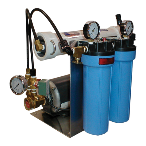
WET GRO User manual

G
GR
RO
O
R
Re
ev
ve
er
rs
se
e
O
Os
sm
mo
os
si
is
s
W
Wa
at
te
er
r
T
Tr
re
ea
at
tm
me
en
nt
t
S
Sy
ys
st
te
em
m
I
IN
NS
ST
TA
AL
LL
LA
AT
TI
IO
ON
N,
,
O
OP
PE
ER
RA
AT
TI
IO
ON
N
A
AN
ND
D
M
MA
AI
IN
NT
TE
EN
NA
AN
NC
CE
E
M
MA
AN
NU
UA
AL
L

- 2 -
WELCOME
This manual is provided for installation, operation, and maintenance of a Reverse Osmosis (RO) water purification
system designed and built by WET. It is intended to be used, along with the component manufacturer literature
included in the Appendix, to provide comprehensive and accurate information for the operation of this RO system.
WET wants to ensure your complete satisfaction with their products and services. Contact your WET
representative for sales, technical support, and service using the contact information provided with this manual.
DISCLAIMER AND LIMITATIONS
This manual discloses proprietary information of WET. This information is provided for the purpose of operating
and maintaining its RO systems, and may not be used for any other purpose.
It is recommended that this manual be read and understood before performing installation, operation, and
maintenance of the RO system. The equipment warranty may be voided if instructions are not followed correctly.
The information provided may not cover all possible variations of detail in relation to equipment use. Please
contact the WET Service Department for any technical questions that are not specifically answered in this manual.
The Seller reserves the right to make enhancements or changes that may not be included in the manual.
Therefore, it is understood that the material presented here is subject to change without notice and is for
informational purposes only.
This manual is believed to be complete and accurate at the time of publication. However, WET assumes no
responsibility for the technical content of the manufacturer literature. Due to the inability to verify all vendor-
provided materials, WET assumes no responsibility for any errors and shall not be liable for damages in connection
with the use of this manual.
© Copyright 2006 XYLEM WET. All rights reserved.
IMPORTANT USER INFORMATION
PLEASE DO NOT DISCARD
THIS MANUAL CONTAINS IMPORTANT INFORMATION WHICH SPECIFICALLY APPLIES
TO THIS UNIT. THIS INFORMATION MAY BE NEEDED AS REFERENCE DURING ANY
FUTURE SERVICING OF THE SYSTEM.
RO MODEL_______________________________
INSTALLED BY____________________________
TELEPHONE______________________________
INITIAL STARTUP DATE____________________
W
Wa
at
te
er
r
E
Eq
qu
ui
ip
pm
me
en
nt
t
T
Te
ec
ch
hn
no
ol
lo
og
gi
ie
es
s
1
10
06
66
61
1
N
Ne
ew
wk
ki
ir
rk
k
S
St
tr
re
ee
et
t
D
Da
al
ll
la
as
s,
,
T
TX
X
7
75
52
22
20
0
9
97
72
2-
-2
24
47
7-
-4
44
44
40
0
h
ht
tt
tp
p:
:/
//
/w
ww
ww
w.
.w
we
et
tp
pu
ur
re
ew
wa
at
te
er
r.
.c
co
om
m

- 3 -
Safety Check Item
Don’t Do This
Special Attention
SAFETY NOTES – READ AND UNDERSTAND BEFORE PROCEEDING
Safety Check Item
Don’t Do This
Special Attention
WARNING
√High Voltage Electricity √Spinning Parts
√High Pressure Components √Pressurized Water
√Hazardous Chemicals √Noise
Failure to follow good safety practices and the instructions included in this manual
may result in damage to the unit, its surroundings, personal injury or death.
Please take all possible precautions when working on or around this unit.
Pressure
Reverse Osmosis units operate by forcing water at high pressure against a semi-permeable membrane. The
higher the TDS (Total Dissolved Solids) of the feedwater, the higher the pressure required to produce
acceptable amounts of purified water. Fresh water typically requires only about 100 psig to suitably overcome
osmotic pressure, while salt water may require up to 1000 psig. Even a small leak at elevated pressures can
be dangerous.
Electricity
Electricity and water DO NOT MIX. Every effort is made to insure that the electrical equipment on our systems
is resistant to water intrusion. Once installed, the system is subject to many factors beyond our control.
•The reject water of this RO unit is a concentrated saline solution with high electrical conductivity. Spills
should be immediately cleaned. Leaks of any kind should be repaired as soon as possible.
•Check all electrical components on a regular basis to insure that water-resistant seals are still in place and
functional.
•DO NOT DRILL HOLES IN THE TOP SURFACE OF ANY ELECTRICAL BOXES.
Chemicals
•Exposure to the highly concentrated reject water, especially at the high pressures of an operating RO unit,
can cause injury or permanent damage to the eyes, skin, and mucous membranes.
•Exposure to the chemicals used in cleaning, disinfection, and preservation is dangerous and may cause
permanent damage.
•Test all hoses and connections before using any cleaning system to clean or preserve the membranes. Do
NOT allow worn hoses or fittings to be used.
•Avoid contact with chemicals by wearing eye and skin protection equipment. Avoid breathing chemical
fumes.

- 4 -
Table of Contents
Section Page
System Specifications ............................................................................................................................ 5
Installation............................................................................................................................................... 6
Operation ................................................................................................................................................ 9
System Maintenance ............................................................................................................................ 10
Cleaning................................................................................................................................................ 12
Troubleshooting .................................................................................................................................... 14
Drawings
GRO 150-700 RO PSI Diagram
GRO 150-700 RO Unit Layout
GRO 150-700 Electrical Schematic

- 5 -
System Specifications
GRO REVERSE OSMOSIS SYSTEMS
Model
Product
Feedwater
Reject
Pipe Size (inches)
GPM
(LPM)
GPM
(LPM)
GPM
(LPM)
Inlet
Product
Reject
GRO 150
0.1
0.39
0.33
1.3
0.23
0.87
3/8"
1/4"
1/4"
GRO 250
0.17
0.65
0.48
1.8
0.31
1.17
3/8"
1/4"
1/4"
GRO 500
0.34
1.3
0.86
3.3
0.52
1.97
3/8"
1/4"
1/4"
GRO 700
0.48
1.8
1
3.8
0.52
1.97
3/8"
1/4"
1/4"
Note: 1) Product flow is the MAXIMUM recommended flow.
2) Reject flow is the MINIMUM recommended flow.
3) Pump pressure must not exceed 200PSI (13.4 Bar)
Typical Operating Parameters
SPECIFICATIONS ------------------------------------------------------------------------------------- T.F.C. MEMBRANE
Membrane Feed Pressure ---------------------------------------------------------------------- 20-90 psi (275-620 kPa)
Feed Water TDS--------------------------------------------------------------------------------- 300-1000 ppm (also mg/l)
Temperature ----------------------------------------------------------------------------------------------- 40-90°F (4.4-32°C)
pH ------------------------------------------------------------------------------------------------------------------------------- 2-11
Hardness --------------------------------------------------------------------------------------- 51.00 ppm/ 3 grains per gal.
Iron-----------------------------------------------------------------------------------------------------------0.2 ppm (also mg/l)
Chlorine ------------------------------------------------------------------------------------------------------------------- 0.0 ppm
Turbidity-------------------------------------------------------------------------------------------------------------- 1 NTU max.
SDI --------------------------------------------------------------------------------------------------------------------------- 5 max.
Recovery = PRODUCT flow ÷ FEED flow
FEED flow = PRODUCT flow + REJECT flow

- 6 -
Installation
Initial Inspection
On receipt of the RO unit, note any damage on appropriate shipping documents. File damage claims with
the freight carrier immediately.
Install Requirements
oThe GRO unit requires an adequate water supply, with a line pressure of at least 30 PSI / 2.1
Bar (50 PSI / 3.5 Bar maximum). PVC pipe or other noncorrosive plumbing should be used.
oThis unit is tested and the membranes are preserved before shipment to insure quality
and performance. This preservative solution MUST be flushed completely from the
unit. On new installations, DO NOT ALLOW THE GRO PRODUCT WATER TO
FLOW INTO A STORAGE TANK OR BE USED UNTIL THE G-RO UNIT HAS
RUN FOR ONE HOUR.
oWhen installing a GRO system that utilizes a booster pump in an enclosed area, be
sure that there is adequate ventilation to dissipate the heat from the motor. Otherwise
the heat buildup can weaken the plastic tubing and may cause it to burst under pump
pressure.
oChlorine MUST be removed from the feedwater if present. Chlorine will damage the thin film
composite membrane and void the warranty! If activated carbon is used to remove chlorine,
the carbon MUST be rinsed to remove small carbon fines before the RO unit is operated or
fouling of the membranes will occur.
Install Recommendations
This unit combines the use of high pressure water and electricity.
Any electrical connections to the electrical control box should be
protected from water or moisture intrusion. Tight fXyleming
grommets or watertight hubs should be used to protect all entry
points. Periodic checks of the interior of the control box should be
performed to inspect for water damage.

- 7 -
Installation
oTo maximize product water output, a non-pressurized (atmospheric) storage tank should be used
with ALL GRO series RO systems. A plastic (preferably polyethylene) or stainless-steel tank is
recommended with an atmospheric vent and an overflow piped to drain. If a pressurized storage
tank is used, the back pressure will reduce the GRO product output by up to 40%. If a
pressurized storage tank is used, then a 20/40 PSI (1.3/2.6 Bar) pressure switch is necessary to
turn the GRO unit on and off automatically.
A liquid level switch (or pressure switch or float switch, if used) is required to initiate
automatic operation of the GRO system. The switch should have a high and low
activation point with an adequate dead band to prevent the GRO unit from turning OFF and ON
too frequently. A normally closed contact is required so that when the tank fills to the required
level, the OPENING of contacts shuts the GRO unit OFF.
oFor long term performance with minimum maintenance:
Chlorine is removed from the feedwater
Hardness is removed from the feedwater
Iron is removed from the feedwater
If a water softener or automatic carbon filter is used, it should be set to regenerate when the
RO unit is not running, usually at night.
Hookups
1. (Supply) Connect the carbon filter to the GRO unit at the prefilter using non-corrosive hose or
pipe. If no chlorine is present in the feed water system and a carbon filter is not being used, tap
into the main feed water line with a tee or other suitable fitting for connection to the GRO feed
water line.
2. (Reject) Attach the supplied tubing to drain and connect the other end to the reject fitting as
marked. Use an air gap to prevent the possible backflow to the unit.
3. (Product) Attach one end of the supplied tubing to the GRO unit product fitting as marked and
connect the other end to the storage tank.
Do NOT install isolation valves in the Feed or Permeate (Product) lines. Pressures and
temperatures can reach levels where piping and interconnects may fail, causing damage,
personal injury or death. If isolation valves MUST be used, be sure they are lockable and
are secured in the OPEN position during operation of the RO unit.
4. Connect the correct power (voltage) to the GRO unit. All units are provided with a power cord
that will plug into an outlet. GRO units are available in 110-120 VAC and 220-240 VAC.
Current requirements for the units vary with the capacity of the unit and the required pump
power.

- 8 -
Installation
5. To connect a product tank level switch to the GRO unit, BE SURE THAT ALL POWER IS OFF!
Open the electrical control box and remove the jumper between terminals 1 and 2. Connect the
level switch between these terminals.
The G-RO unit may be operated manually without the use of a level switch.
Carbon Tank
1. (If a carbon tank is to be used for chlorine removal) With the carbon tank disconnected from the
GRO unit, allow water to slowly fill the tank from the reverse direction, i.e., outlet to inlet, to
initially rinse the carbon. Run the water through the tank in this manner for 15 minutes, directing
the water to drain.
2. Connect the tank from the inlet to outlet and run the water through the tank for an additional 5-
minute rinse to drain.
Failure to follow backwash and rinse the carbon tank, as described above, will
allow carbon to enter the RO membrane assembly and block the water
passages, causing early system failure or degraded performance.
3. If a manual or automatic carbon tank is used for chlorine removal, use the backwash mode for
an additional 5 minutes rinse to drain.
Do NOT replace the 5 micron pleated cartridge with an activated carbon cartridge.
An activated carbon cartridge does not have enough surface area to effectively
remove all of the chlorine in the feedwater. Severe pressure drops may also occur,
causing the unit to continuously cycle on and off and damage the pump.

- 9 -
Operation
oOn new installations, DO NOT allow product water to flow into a storage tank or be
used until the unit has run for one hour.
oIf the system is equipped with a cast iron pump, all liquid in the pump should be
drained before start-up by disconnecting the discharge hose from the pump outlet.
Unit Startup
1. Open the Feed and Reject valves, then start the system using the On-Off switch or the plug.
2. Adjust the reject valve until the product flow reaches the proper flow rate. (See System
Specifications) As the valve is closing the product flow will increase, the reject flow will fall, and
the pump pressure will rise.
DO NOT exceed the recommended product flow rate or fall below the minimum
reject flow rate shown in the System Specifications for your unit or membrane
fouling could occur very rapidly.
3. After the proper flows have been set and an adequate amount of water has been pumped to
drain, record all flows, pressures, TDS levels and water temperature. This initial start-up
information is very important when determining the system’s performance over time. (For the
most accurate TDS readings, let the GRO unit run for at least 15 minutes.)
Unit Shutdown
The standard GRO system with no options is turned off manually with the On-Off switch or plug.
Because the standard unit is not equipped with an automatic shut-off valve, the Feed valve must also be
closed, or water will continue flowing through the system producing small amounts of water with poor
quality.
For units equipped with a product water tank pressure switch or a level switch, the unit will automatically
shut off when the storage tank is full or at a desired pressure.
To prevent biological growth during system shutdowns (one week or longer) the membranes must
be immersed in a preservative solution.
If sanitization of the GRO system is required, the GRO system must be in use for at least six hours
before formaldehyde can be used. If the membranes are exposed to formaldehyde before being
in use for this period of time, severe damage will result. Other disinfecting solutions such as
hydrogen peroxide or renalin can be used. Do not allow the solution to come in contact with the
cast iron pumps. For further information, contact your local representative.

- 10 -
System Maintenance
Pre-Filters
Check the pre-filter inlet/outlet pressure gauges for pressure drop. If the differential pressure increases by
more than 10 PSI (0.7 Bar) from the ORIGINAL pressure at the time of installation, then either clean or
replace the cartridge.
Activated Carbon
Chlorine will rapidly degrade the performance and life expectancy of the RO membranes. Check for
chlorine breakthrough by testing with a chlorine test kit.
To test for free chlorine residual, fill a test jar with water downstream of the activated carbon tank. If
chlorine is indicated, replace the activated carbon tank immediately. On chlorinated water supplies the
activated carbon should be replaced every 6 MONTHS OR SOONER to prevent chlorine break-through.
Blending Valves
Installations that are using blending valves to mix hot and cold water going to the GRO unit should be
checked for the maximum temperature of the hot water, particularly during the winter. Hot water leaking
by the blending valve could result in leaking RO membrane assembly and fittings. Feed water
temperature should be kept below 100 degree F (37.5 degrees C).
Membranes
Always keep moisture in the membrane pressure vessel, and always keep the ends plugged (be careful
not to cross thread or over tighten, as a cracked end plug may result). If freezing weather conditions
exist, drain water from the RO membrane assembly during shutdown periods and plug the holes.
Pump
DRIVE COUPLING
Check the “V” clamp connecting the motor to the pump at least once per month. Motor and pump
should move as one unit. Any play between the pump and the motor will cause the coupling to wear
excessively, damaging the motor and pump bearings. “Butterfly” wear of the shaft coupling and
resultant bearing failure may not be covered under warranty.
INLET PRESSURE
Minimum desired feed water pressure should be 20 PSI (1.4 Bar) after the prefilter.
OUTLET PRESSURE
Check pump outlet pressure weekly (or more often if use warrants) and adjust or clean as indicated.
Consistent high pressures may indicate blockage or severe membrane fouling.
RO pump outlet pressure should not exceed 200 PSI (GRO 150 – GRO 700). Pressures
in excess of those shown will reduce the useful life of the membranes and system
components and may cause a hazardous situation resulting in injury or death.

- 11 -
System Maintenance
STANDING LIQUID
If the system is equipped with a cast iron pump, liquid should not be allowed to sit in the pump
discharge casing during the periods of non use. Drain liquids by disconnecting the discharge hose
from the pump outlet.
Water Quality
For maximum performance and reduced frequency of membrane cleaning cycles, remove or sequester
calcium carbonate, ferrous iron, and calcium sulfate from the feed water via water softening or an anti-
scalant chemical feed system. (Use test kit to check water quality.)
Follow these basic guidelines to minimize unplanned downtime:
•Complete Log Sheets regularly. Add data as needed.
•Review the data periodically. Look for unusual readings and trends.
•Be familiar with your equipment. Periodically inspect all components.
•Use sight, sound, smell and touch.
• Look for leaks
• Listen for unusual noises
• Sniff for unusual odors
• Touch for heat and vibration

- 12 -
Cleaning
In normal operation, the membranes in the GRO system pressure vessel(s) become fouled by mineral
scale, biological matter, colloidal particles and insoluble organic constituents. Deposit build up on the
membrane surfaces can cause loss of water output, loss of salt rejection, or both.
The membranes should be chemically cleaned whenever the GRO unit flows and/or
pressures vary by more than 10% from the initial operating conditions.
Several conditions can cause a reduction in the water quality and/or water production. The following
items should be checked before considering cleaning.
1. Temperature change
This GRO unit is designed for water at 25 degrees C and 250 MG/L TDS. Lower water
temperature will result in LESS water passing through the membrane. Higher water
temperature will result in MORE water passing through the membrane. As a rule, at a
given pressure and TDS level, for each one degree change in water temperature the
change in water production is approximately 2%. Thus, if the water temperature is 5
degrees C, the amount of water produced will be 40% less than at 25 degrees C.
2. TDS level increase
As the TDS (Total Dissolved Solids) level climbs, the amount of water passing through
the membrane decreases. If the TDS level has climbed since the time of installation the
unit will produce less water. Check the TDS level of the feed water and compare it with
the TDS level at the time of installation. If the TDS levels have climbed, the rejection rate
will have to be increased to reduce the TDS level build-up within the membrane. Use the
TDS tester #661-10 for up to 1250 MG/L.
3. Prefilters plugged
Five Micron - A dirty prefilter can reduce the amount of water and the pressure going to
the GRO unit. If the cartridge appears dirty it should be cleaned or replaced. On
extremely dirty water a larger prefilter may be needed. When cleaning the prefilter, check
its condition. If signs of wear appear, replace it immediately.
Activated Carbon - The activated carbon prefilter is used to reduce the volatile organic
substances and chlorine. It should be changed every 6 months or sooner if chlorine is
detected after the activated carbon tank.
4. Change in flow rates or water pressure change
Check the product and reject flow rates to determine any change from normal conditions.
Adjust the flows and pressures if necessary to maintain the proper settings.

- 13 -
Cleaning
Cleaning Procedure
When working with any chemicals, follow accepted safety practices. Use eye and
skin protection and positive ventilation when needed.
1. Obtain equipment:
Pump
Hoses
5 Micron Filter
Mixing Tank
Cleaning chemicals
Rags
Protective gear
2. Prepare the GRO unit for cleaning:
a. Disconnect the pump discharge manifold from the pump and connect the manifold to the
cleaning system.
b. Place the product line from the RO unit into the mixing tank.
c. Disconnect the reject line coming from the last membrane and place it in the mixing tank.
d. To make up the cleaning solution, mix sodium hydroxide (NaOH) with RO product water (2
gallons of water per membrane) to obtain a 0.1% solution (pH 11-12, 30 degrees C maximum
water temperature).
3. Once the solution is mixed, pump it through the membranes at less than 50 PSI and recirculate
back to the mixing tank for 30 minutes.
Test both reject and product water for traces of cleaning or
disinfection chemicals before sending water to the service
connection or product storage.
4. After cleaning, the RO product water should be pumped to drain for at least 10 minutes or until the
water is clear.
If the water quality and/or production does not change after correcting
ALL of the conditions listed in this section and performing a thorough
cleaning, contact your GRO supplier for assistance.

- 14 -
Troubleshooting
This is a listing of some common problems, their causes, and the appropriate remedy. For conditions
other than those listed here, contact your GRO sales representative for guidance.
NOT MAKING ENOUGH WATER
1. Reject ratio too low
2. Product line blocked
3. Pressure too low
4. TDS too high
5. Membrane fouled
6. Prefilter plugged
7. Pressure tank has too much air pressure (if used)
MAKING TOO MUCH WATER(possible reasons)
1. O-ring by-pass on membranes
2. Chlorine damage to membranes
3. Temperature increase
4. Reverse flow through membrane (causing a rupture in the membrane)
PERMEATE TDS TOO HIGH(possible reasons)
1. O-ring by-pass in RO membrane assembly
2. Chlorine damage to membranes
3. Membrane fouling
4. Ruptured membrane
5. Increase in feed water TDS
6. High pH in feed water (over 9.0)
PUMP CYCLES ON AND OFF (every few seconds)
A defective pressure switch could cause the pump to cycle rapidly on all models. Check for leaks in
the product line. If there is a pressure tank in line, be sure it is properly pressurized.

- 15 -

- 16 -
Rev 4
October 2018
Table of contents
Other WET Water Filtration System manuals
Popular Water Filtration System manuals by other brands

Diffraction
Diffraction Boltwood Cloud Sensor III user manual

Drinking Fountain Doctor
Drinking Fountain Doctor EFHFA8 2 Installation use and care manual

Bühler technologies
Bühler technologies AGF-VA-350 Installation and operation instruction

Speck pumpen
Speck pumpen BADU Star 69/12 original operation manual

JRC
JRC NSVS614 manual

Aquafine
Aquafine Avant Series ACCOMPANIMENT TO THE INSTALLATION, OPERATION AND MAINTENANCE MANUAL