Wetstyle FRAME LINEA Series User manual

- FRAME LINEA CABINET INSTALL GUIDE -
(2018-05-07)
1/14
FRAME LINEA CABINET INSTALLATION GUIDE
INDEX
Before you begin p.1
Insta ation
•Wa preparation – Surface Mounted p.3
•Wa preparation – Recessed Mounted p.4
•Cabinet preparation p.7
•E ectrica preparation p.8
•Cabinet insta ation p.9
•C eaning guide p.14
•Warranty p.14
BEFORE YOU BEGIN
T ank you for c oosing from WETSTYLE’s line of quality products.
Please note t at prior to s ipment from t e manufacturing facility, t e furniture you
ave received as passed quality control and was in excellent condition upon leaving
t e WETSTYLE facility.
We recommend t at you carefully inspect t e product prior to its installation. If t ere
are any defects, please contact t e dealer from w om you purc ased t e product
and please DO NOT install t e furniture. WETSTYLE will not be eld responsible for any
defects or damage discovered once t e furniture is installed.
It is ig ly recommended t at a professional undertake t e installation of t e Vanity.
Please read t is guide carefully to ensure t e proper installation and reliability of your
product for many years to come.
For assistance, please call customer service at 1.888.536.9001.

- FRAME LINEA CABINET INSTALL GUIDE -
(2018-05-07)
2/14
WARNING!
To reduce t e risk of fire, electric s ock, or injury to persons, please read t ese instructions
t oroug ly before using t is product.
Important Safety Instructions must be kept for future use.
TOOLS AND EQUIPMENT
• Drill and bits
• Measuring tape
• Protective paper
• Pencil
• Level
• Protective eyeglasses
•Wood screw #8, 5/8" and 1-½" long
• Wood screw #10, 3" and 4" long
IMPORTANT
T is installation mig t require custom placement of studs relative to t e position of t e
product in t e room. Please read t e instructions related to your Vanity model carefully.

- FRAME LINEA CABINET INSTALL GUIDE -
(2018-05-07)
3/14
MIRROR CABINET
The FRAME LINEA Mirror Cabinet may be surface or recessed mounted. In either installation
scenario special wall preparation is needed prior to installation of the unit.
A. MIRROR CABINET - SURFACE MOUNTED
Wall Preparation Steps
1.1 Make sure t at walls and floor are straig t and level.
1.2 Determine overall cabinet dimensions.
1.3 Determine t e desired location of t e cabinet.
1.4 T e distance between studs s ould not be more t an 16".
1.5 Metal studs s ould be reinforced vertically by 2" x 4" wooden studs. T is is
applicable for bot Frame Cabinet and Vanities.
1.6 Metal and wooden studs s ould be reinforced orizontally wit 2" x 6" wooden
studs at anc oring eig ts:
• 73" along t e full widt of t e mirror cabinet
1.7 Do not apply t e product to t e wall surface until all braces and mounting clips
ave been installed and all plumbing and electrical roug ins ave been
completed.
* See diagram on page 9
Heig ts:
Mirror Cabinet (Monarc -clips): 73’’
Mirror Cabinet (Wall Anc or)*: 47 ½’’
& 72 ½’’
Electrical Feed: 68’’
73”

- FRAME LINEA CABINET INSTALL GUIDE -
(2018-05-07)
4/14
B. MIRROR CABINET - RECESSED MOUNTED (ignore this step if SURFACE MOUNTED and
proceed to section C)
Wall Preparation Steps
T e FRAME recessed cabinet collection is designed for a 4” (101.6 mm) deep opening and
needs special wall preparation.
1. Make sure t at walls and floor are straig t and level.
2. Determine overall cabinet dimensions.
3. Determine t e desired location of t e cabinet.
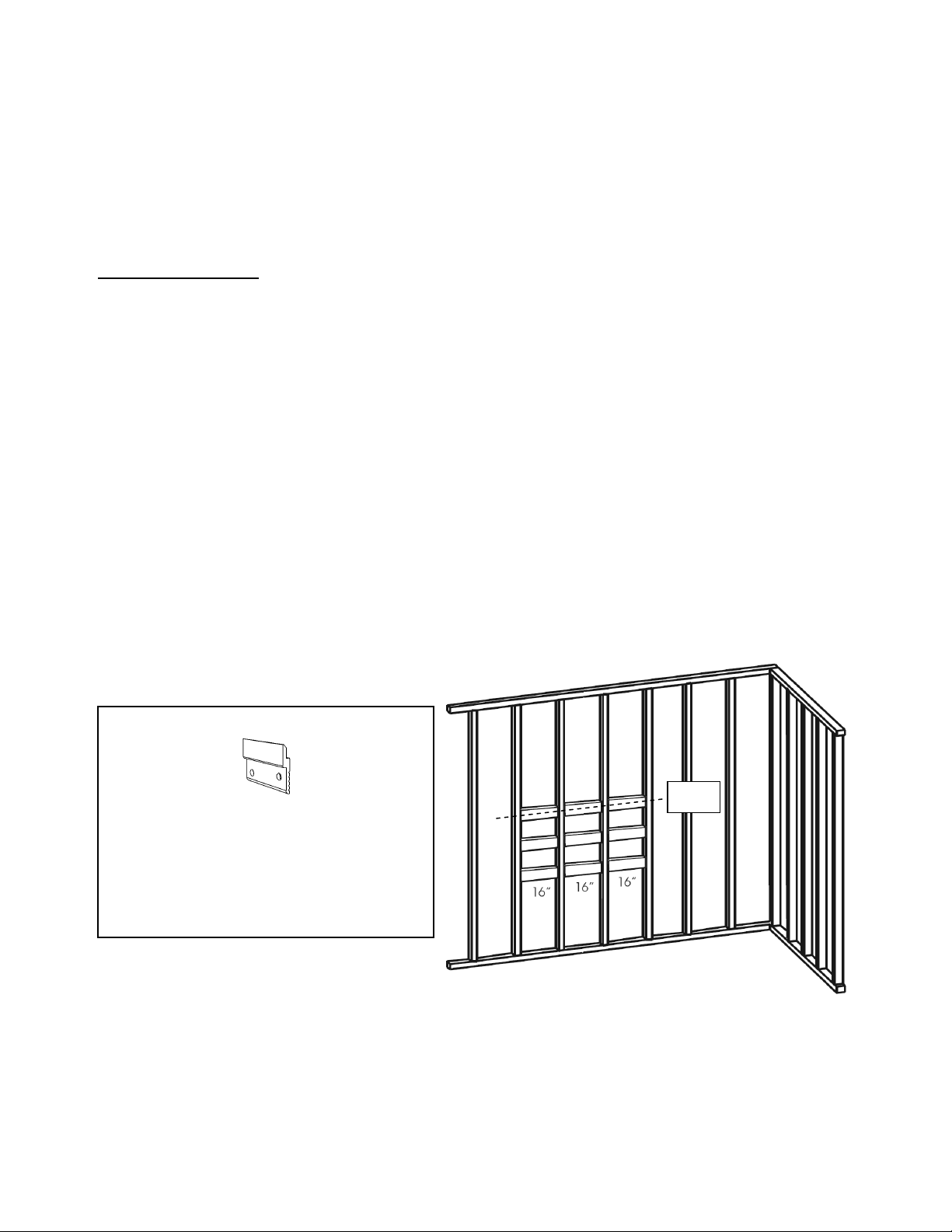
4. T e distance between studs is determined by t e cabinet size you purc ased.
Refer to diagrams below to find t e correct stud position to mount your cabinet.
5. Metal studs s ould be reinforced vertically by 2" x 4" wooden studs.
6. Metal and wooden studs s ould be reinforced orizontally wit 2" x 6" wooden
studs at t e position of t e wall opening for your corresponding cabinet model.
(See CHART for Rough Wall Openings below)
7. Do not apply t e product to t e wall surface until all braces and mounting clips
ave been installed and all plumbing and electrical roug ins ave been
completed.
8. Do not apply t e wall surface until you test your stud placement wit your
cabinet size and make sure t e cabinet will cover t e roug wall opening.
RECESSED MIRROR CABINET– ROUGH OPENINGS
Model Product size Opening size
FRL24MEL-REC
23 7/8”x 30”
60.6 cm x 76.2 cm
23 3/16” x 29 5/16”
58.9 cm x 74.5 cm
FRL36MEL-REC
35 7/8”x 30”
91.1 cm x 76.2 cm
35 3/16” x 29 5/16”
89.4 cm x 74.5 cm
FRL48MEL-REC
47 7/8’’x 30”
121.6 cm x 76.2 cm
47 3/16’’ x 29 5/16”
119.9 cm x 74.5 cm
FRL60MEL-REC
59 7/8”x 30”
152.1 cm x 76.2 cm
59 3/16” x 29 5/16”
150.3 cm x 74.5 cm
FRL72MEL-REC
71 7/8 ”x 30”
182.6 cm x 76.2 cm
71 3/16” x 29 5/16”
180.8 cm x 74.5 cm

- FRAME LINEA CABINET INSTALL GUIDE -
(2018-05-07)
5/14
WALL OPENING DIAGRAM
* Please note that rough opening sizes include a 5/32” gap all around the cabinet for levelling
purposes. This will yield an actual 11/32” overlay of the cabinet over the opening
Horizontal opening
FRL24MEL-REC = 23 3/16” (58.9 cm)
FRL36MEL-REC = 35 3/16” (89.4 cm)
FRL48MEL-REC = 47 3/16’’ (119.9 cm)
FRL60MEL-REC = 59 3/16” (150.3 cm)
FRL72MEL-REC = 7 3/16” (180.8 cm)
Vertical Openings
FRL24MEL-REC,
FRL36MEL-REC,
FRL48MEL-REC,
FRL60MEL-REC,
FRL72MEL-REC =
29 5/16” (74.5 cm)
Suggested distance
from finis ed floor
Cabinet eig t = 45 ½’’
(115.6 cm)

- FRAME LINEA CABINET INSTALL GUIDE -
(2018-05-07)
6/14
9. Once cabinet is positioned wit in wall opening, secure fixture wit 4x 1-½" long
No.8 wood screws t roug pre- oles provided wit top and bottom inge
mounting plates.

- FRAME LINEA CABINET INSTALL GUIDE -
(2018-05-07)
7/14
C. CABINET PREPARATION
Prior to installation
1. Carefully remove unit from packaging.
2. Gently remove packaged glass s elves, wooden s elves and ardware bag
from wit in cabinet.
3. If your unit as t e defogger option, you must disconnect t e Defogger
Connectors prior to removing t e cabinet doors. Unscrew security ring (1/4 turn)
on connector and remove as depicted below.
4. Remove and store doors w ile you continue installation.

- FRAME LINEA CABINET INSTALL GUIDE -
(2018-05-07)
8/14
NOTE: ELECTRICAL PREPARATON
It is mandatory to have a qualified and licensed electrician install and provide all
wiring for the cabinet
WARNING: To reduce t e risk of electrical s ock, s ut off power before wiring t e
cabinet.
CAUTION: Requires 110 VAC 15 Amp circuit.
CAUTION: Proper bonding must be supplied to t e mirrored cabinet as to equalize
ground potential and eliminate static disc arge between components. Please bond
t e entire system at t e indicated location wit supplied ardware.
CAUTION: Cabinet must be wired to a 15 Amp GFI (Ground Fault Interrupter) circuit
breaker when used in bat rooms and all ot er locations required by t e local Electric
Code.
5.
Cabinet
electrical
outlet

- FRAME LINEA CABINET INSTALL GUIDE -
(2018-05-07)
9/14
D. CABINET INSTALLATION
1. In the case of SURFACE MOUNTED the FRAME mirror cabinet must be wall-
mounted with the MONARCH mounting clips provided with the furniture as seen
in the exhibit below. These Monarch mounting clips are used to mount cabinet
on wall for levelling and installation support. The cabinet is secured to the wall
using security tie-down, 3" long #10 wood screws at wall post, owever t is is to
be done at a later step and after wooden console and electrical preparation as
explained in next sequence of steps.
Monarch mounting clip
CAUTION: Cabinet is to be ung onto t e Monarc Clips provided
NOTE: Mounting clips and s elf pins are packaged wit glass s elves.
2. Align and level mounting clips according to orizontally reinforced studs and
desired cabinet eig t.
3. Space mounting clips evenly along widt of cabinet.
4. Install mounting Clips to t e wall using 3" long #10 wood screws. Fasten securely.
5. Unfasten wooden consoles by removing access screws at top and bottom of t e
cabinet.
WALL – Back view
Level
WALL
Access screws
NOTE (Number of Monarch c ips per mode )
FRL24MEL: 2 clips
FRL36MEL & FRL48MEL: 3 clips
FRL60MEL & FRL72MEL: 4 clips
Top
Bottom
Note
Electrical outlets &
switc es on bottom

- FRAME LINEA CABINET INSTALL GUIDE -
(2018-05-07)
10/14
6. Gent y turn t e wooden console to its side wit in t e cabinet. Be aware t at
t ere are wiring connections inside. Installation s ould be cautious and gentle at
t is stage.
7. Feed electrical wire t roug access oles located in t e center and back of
cabinet.
8. Carefully lift t e cabinet and mount onto t e Monarc mounting clips.
Bonding
lug
Access
Hole
Level
Level
clips

- FRAME LINEA CABINET INSTALL GUIDE -
(2018-05-07)
11/14
9. Fasten down t e cabinet to t e wall by adding security tie-down, 3" long #10
wood screw at wall post. Do not over tig ten as t is may damage t e backing
(wit in console).
10. Secure electrical wire wit cable connector.
11. Bond t e entire electrical system at t e indicated location wit supplied
ardware. (depicted at step 11)
12. Make connections wit WAGO terminal blocks (insert positive and negative
leads to respectful terminal blocks as per electrical diagram wit w ite to w ite,
black to black)
13. Carefully replace console, making sure not to crimp or pinc wires and
connections.
WAGO
terminal

- FRAME LINEA CABINET INSTALL GUIDE -
(2018-05-07)
12/14
14. Fasten wooden console by replacing access screws at top and bottom of t e
cabinet.
NOTE: 60’’ & 72’’ Cabinets - Electrical Outlet on secondary Wooden Console (60’’ & 72’’
Cabinets) - Apply steps 9 to 18.
FINAL ASSEMBLY
15. Mount doors onto inge plates.
16. Doors may be adjusted wit inge adjustment features.
17. Connect defogger cord into t e outlet connector. Pus in and turn counter-
clockwise to lock. (as per step 3)
18. Turn on power.
19. Test electrical options by activating electrical switc es on consoles.
20. Defogger option: Left and switc
21. LED lig ting option: Rig t and switc
Secondary
console
Primary
console

- FRAME LINEA CABINET INSTALL GUIDE -
(2018-05-07)
13/14
22. Insert Adjustable s elf pins to wooden console and aluminum sidings.
23. Insert glass s elves wit in adjustable s elf pins and secure into place on upper 3
sets of oles.
CAUTION: Maximum load 30 LBS
NOTE: Be sure to turn t e defogger off w en not in use. W en t e defogger is on, t e
center area of t e mirror will remain fog-free. If t e defogger does not function, please
verify if defogger connectors are properly inserted.
Adjustable
S elf Pins

- FRAME LINEA CABINET INSTALL GUIDE -
(2018-05-07)
14/14
CLEANING GUIDE
WETSTYLE FRAME LINEA FURNITURE is made from Oak or Walnut.
WETSTYLE Furniture is ultra-easy to clean: after use, simply wipe wit a soft clot to remove
any surface dirt. For standard cleaning, we recommend using warm water wit mild soap.
Do not use abrasive products or cream cleaners. Never use petroleum-based products
w en cleaning t e wood, i.e. paint t inners or ot er solvents, as t ey may damage t e
wood surface. Glass surfaces may be cleaned using standard glass cleaning products.
WARRANTY
T e warranty on WETSTYLE products covers all defects in materials and manufacturing for a
period of one year from t e date on w ic t e owner originally purc ased t e product
directly from WETSTYLE or from an aut orized retailer. T is warranty is valid for t e original
owner only. T is warranty does not apply to cases in w ic a product was incorrectly
installed, or to damage due to negligence, misuse, cigarettes, flames, natural disasters or
ot er accidents.
WETSTYLE is not responsible for any fees or recovery c arges t at may ave been
generated by t e purc ase of a product t at is not adequate for an existing building
structure.
At t e discretion of t e manufacturer, t e guarantee is limited to t e repair or replacement
(of a product of equal or greater value) at t e condition t at t e claim is made during t e
guarantee period to an aut orized dealer or directly to WETSTYLE. T e andling fees and all
ot er c arges related to t e product replacement are not covered by t e guarantee.
Printed in Canada
www.WETSTYLE.CA – Montreal – Canada
Tel. 450.536.9000 – 1.888.536.9001 – Fax. 450.536.0202
This manual suits for next models
5
Other Wetstyle Indoor Furnishing manuals
Popular Indoor Furnishing manuals by other brands

J.Burrows
J.Burrows TORO TOR18LCBKT Assembly instructions

Bensons for Beds
Bensons for Beds Hip Hop STK268002 Assembly instructions

Riverside Furniture
Riverside Furniture 24530 Assembly instructions

Coaster
Coaster 205070KE Assembly instructions

John
John 5059413795008 Assembly and Care Guide

Seconique
Seconique CORONA 5' TABLE Assembly instructions

Home Decorators Collection
Home Decorators Collection CHANNING CGBV3022D Use and care guide

AIS
AIS Divi installation instructions

Safco
Safco 8916 Assembly instructions

Artist's Loft
Artist's Loft 10299013 Assembly instructions

m-Dimension
m-Dimension 8514 Assembly instructions

Hülsta
Hülsta hs.450 Important product information