Wetstyle Frame Series User manual

installation guide
Frame collection
www.WETSTYLE.CA


- FRAME INSTALL GUIDE -
(2013-08-28)
1/20
FRAME CABINET INSTALLATION GUIDE
BEFORE YOU BEGIN
Thank you fo choosing f om WETSTYLE’s line of quality p oducts.
Please note that p io to shipment f om the manufactu ing facility, the fu nitu e you
have eceived has passed quality cont ol and was in excellent condition upon leaving
the WETSTYLE facility.
We ecommend that you ca efully inspect the p oduct p io to its installation. If the e
a e any defects, please contact the deale f om whom you pu chased the p oduct
and please DO NOT install the fu nitu e. WETSTYLE will not be held esponsible fo any
defects o damage discove ed once the fu nitu e is installed.
It is highly ecommended that a p ofessional unde take the installation of the cabinet
and vanity.
Please ead this guide ca efully to ensu e the p ope installation and eliability of you
p oduct fo many yea s to come.
Fo assistance, please call custome se vice at 1.888.536.9001.
WARNING!
To educe the isk of fi e, elect ic shock, o inju y to pe sons, please ead these inst uctions
tho oughly befo e using this p oduct.
Impo tant Safety Inst uctions must be kept fo futu e use.
TOOLS AND EQUIPMENT
• D ill and bits
• Measu ing tape
• P otective pape
• Pencil
• Level
• P otective eyeglasses
•Wood sc ew #8, 5/8" and 1-½" long
• Wood sc ew #10, 3" and 4" long
IMPORTANT
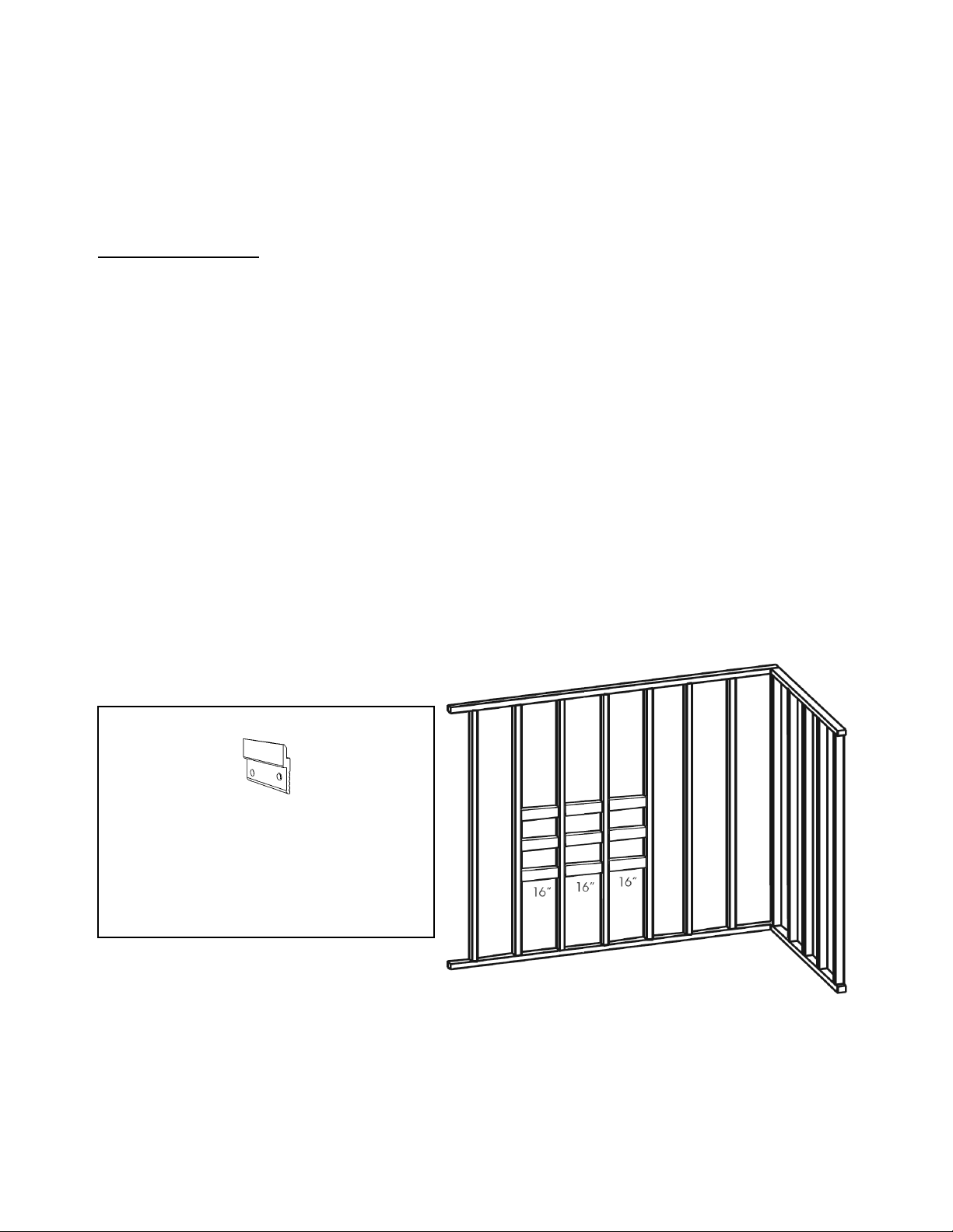
This installation might equi e custom placement of studs elative to the position of the
p oduct in the oom. Please ead the inst uctions elated to you cabinet model ca efully.

- FRAME INSTALL GUIDE -
(2013-08-28)
2/20
MIRROR CABINET
The FRAME Mirror Cabinet may be surface or recessed mounted. In either installation
scenario, s ecial wall re aration is needed rior to installation of the unit.
A. MIRROR CABINET - SURFACE MOUNTED
Wall P epa ation Steps
1.1 Make su e that walls and floo a e st aight and level.
1.2 Dete mine ove all cabinet dimensions.
1.3 Dete mine the desi ed location of the cabinet.
1.4 The distance between studs should not be mo e than 16".
1.5 Metal studs should be einfo ced ve tically by 2" x 4" wooden studs. This is
applicable fo both F ame Cabinet and Vanities.
1.6 Metal and wooden studs should be einfo ced ho izontally with 2" x 6" wooden
studs at ancho ing heights:
• 14 ¾’’ & 30" along the full width of the vanity
• 73" along the full width of the mi o cabinet
1.7 Do not apply the p oduct to the wall su face until all b aces and mounting clips
have been installed and all plumbing and elect ical oughins have been
completed.
* See diag am on page 13
Heights:
Mi o Cabinet (Mona ch-clips): 73’’
Mi o Cabinet (Wall Ancho )*: 47 ½’’
& 72 ½’’
Elect ical Feed: 68’’
Vanity: 14 ¾’’ & 30’’

- FRAME INSTALL GUIDE -
(2013-08-28)
3/20
B. MIRROR CABINET - RECESSED MOUNTED (ignore this ste if SURFACE MOUNTED and
roceed to section C)
Wall P epa ation Steps
The FRAME ecessed cabinet collection is designed fo a 4” (101.6 mm) deep opening and
needs special wall p epa ation.
1. Make su e that walls and floo a e st aight and level.
2. Dete mine ove all cabinet dimensions.
3. Dete mine the desi ed location of the cabinet.
4. The distance between studs is dete mined by the cabinet size you pu chased.
Refe to diag ams below to find the co ect stud position to mount you cabinet.
5. Metal studs should be einfo ced ve tically by 2" x 4" wooden studs.
6. Metal and wooden studs should be einfo ced ho izontally with 2" x 6" wooden
studs at the position of the wall opening fo you co esponding cabinet model.
(See CHART for Rough Wall Openings below)
7. Do not apply the p oduct to the wall su face until all b aces and mounting clips
have been installed and all plumbing and elect ical oughins have been
completed.
8. Do not apply the wall su face until you test you stud placement with you
cabinet size and make su e the cabinet will cove the ough wall opening.
RECESSED MIRROR CABINET ROUGH OPENINGS
Model P oduct size Opening size
FR18ME-REC
17 7/8”x 30”
45.4 cm x 76.2 cm
17 3/16” x 29 5/16”
41.1 cm x 74.5 cm
FR20ME-REC
19 7/8”x 30”
50.5 cm x 76.2 cm
19 3/16” x 29 5/16”
48.7 cm x 74.5 cm
FR24ME-REC
23 7/8”x 30”
60.6 cm x 76.2 cm
23 3/16” x 29 5/16”
58.9 cm x 74.5 cm
FR36ME-REC
35 7/8”x 30”
91.1 cm x 76.2 cm
35 3/16” x 29 5/16”
89.4 cm x 74.5 cm
FR48ME-REC
47 7/8’’x 30”
121.6 cm x 76.2 cm
47 3/16’’ x 29 5/16”
119.9 cm x 74.5 cm
FR60ME-REC
59 7/8”x 30”
152.1 cm x 76.2 cm
59 3/16” x 29 5/16”
150.3 cm x 74.5 cm
FR72ME-REC
71 7/8 ”x 30”
182.6 cm x 76.2 cm
71 3/16” x 29 5/16”
180.8 cm x 74.5 cm

- FRAME INSTALL GUIDE -
(2013-08-28)
4/20
WALL OPENING DIAGRAM
* Please note that rough o ening sizes include a 5/32” ga all around the cabinet for levelling
ur oses. This will yield an actual 11/32” overlay of the cabinet over the o ening
Ho izontal opening
FR18ME-REC = 17 3/16” (41.1 cm)
FR20ME-REC = 19 3/16” (48.7 cm)
FR24ME-REC = 23 3/16” (58.9 cm)
FR36ME-REC = 35 3/16” (89.4 cm)
FR48ME-REC = 47 3/16’’ (119.9 cm)
FR60ME-REC = 59 3/16” (150.3 cm)
FR72ME-REC = 71 3/16” (180.8 cm)
Ve tical Openings
FR18ME-REC,
FR20ME-REC,
FR24ME-REC,
FR36ME-REC,
FR48ME-REC,
FR60ME-REC,
FR72ME-REC =
29 5/16” (74.5 cm)
Suggested distance
f om finished floo
Cabinet height = 45 ½’’
(115.6 cm)

- FRAME INSTALL GUIDE -
(2013-08-28)
5/20
9. Once cabinet is positioned within wall opening, secu e fixtu e with 4x 1-½" long
No.8 wood sc ews th ough p e-holes p ovided with top and bottom hinge
mounting plates.

- FRAME INSTALL GUIDE -
(2013-08-28)
6/20
C. CABINET PREPARATION
Prior to installation,
1. Ca efully emove unit f om packaging.
2. Gently emove packaged glass shelves, wooden shelves and ha dwa e bag
f om within cabinet.
3. If you unit has the defogge option, you must disconnect the Defogge
Connecto s p io to emoving the cabinet doo s. Unsc ew secu ity ing (1/4 tu n)
on connecto and emove as depicted below.
4. Remove and sto e doo s while you continue installation.

- FRAME INSTALL GUIDE -
(2013-08-28)
7/20
NOTE: ELECTRICAL PREPARATON
It is mandatory to have a qualified and licensed electrician install and provide all
wiring for the cabinet
WARNING: To educe the isk of elect ical shock, shut off powe befo e wi ing the
cabinet.
CAUTION: Requi es 110 VAC 15 Amp ci cuit.
CAUTION: P ope bonding must be supplied to the mi o ed cabinet as to equalize
g ound potential and eliminate static discha ge between components. Please bond
the enti e system at the indicated location with supplied ha dwa e.
CAUTION: Cabinet must be wi ed to a 15 Amp GFI (G ound Fault Inte upte ) circuit
breaker when used in bath ooms and all othe locations equi ed by the local Elect ic
Code.
Cabinet
elect ical
outlet

- FRAME INSTALL GUIDE -
(2013-08-28)
8/20
5. In the case of SURFACE MOUNTED, the FRAME mirror cabinet must be wall-
mounted with the MONARCH mounting cli s rovided with the furniture as seen
in the exhibit below. These Monarch mounting cli s are used to mount cabinet
on wall, for levelling and installation su ort. The cabinet is secured to the wall
using secu ity tie-down, 3" long #10 wood sc ews at wall post, howeve this is to
be done at a late step and afte wooden console and elect ical p epa ation as
explained in next sequence of steps.
Monarch mounting cli
CAUTION: Cabinet is to be hung onto the Mona ch Clips p ovided
6. Align and level mounting clips acco ding to ho izontally einfo ced studs and
desi ed cabinet height.
7. Space mounting clips evenly along width of cabinet.
8. Install mounting Clips to the wall using 3" long #10 wood sc ews. Fasten secu ely.
9. Unfasten wooden consoles by emoving access sc ews at top and bottom of the
cabinet.
WALL – Back view
Level
WALL
Access sc ews
NOTE (Number of Monarch clips per model)
FR18ME, FR20ME & FR24ME: 2 clips
FR36ME & FR48ME: 3 clips
FR60ME & FR72ME: 4 clips
Top
Bottom
Note
Elect ical outlets &
switches on bottom

- FRAME INSTALL GUIDE -
(2013-08-28)
9/20
10. Gently turn the wooden console to its side within the cabinet. Be awa e that
the e a e wi ing connections inside. Installation should be cautious and gentle at
this stage.
11. Feed elect ical wi e th ough access holes located in the cente and back of
cabinet.
12. Ca efully lift the cabinet and mount onto the Mona ch mounting clips.
Bonding
lug
Access
Hole
Level
Level
clips

- FRAME INSTALL GUIDE -
(2013-08-28)
10/20
13. Fasten down the cabinet to the wall by adding secu ity tie-down, 3" long #10
wood sc ew at wall post. Do not ove tighten as this may damage the backing
(within console).
14. Secu e elect ical wi e with cable connecto .
15. Bond the enti e elect ical system at the indicated location with supplied
ha dwa e. (depicted at step 11)
16. Make connections with WAGO te minal blocks (inse t positive and negative
leads to espectful te minal blocks as pe elect ical diag am with white to white,
black to black)
17. Ca efully eplace console, making su e not to c imp o pinch wi es and
connections.
WAGO
te minal

- FRAME INSTALL GUIDE -
(2013-08-28)
11/20
18. Fasten wooden console by eplacing access sc ews at top and bottom of the
cabinet.
NOTE: 60’’ & 72’’ Cabinets - Elect ical Outlet on seconda y Wooden Console (60’’ & 72’’
Cabinets) - A ly ste s 9 to 18.
FINAL ASSEMBLY
19. Mount doo s onto hinge plates.
20. Doo s may be adjusted with hinge adjustment featu es.
21. Connect defogge co d into the outlet connecto . Push in and tu n counte -
clockwise to lock. (as pe step 3)
22. Tu n on powe .
23. Test elect ical options by activating elect ical switches on consoles.
24. Defogge option: Left hand switch
25. LED lighting option: Right hand switch
Seconda y
console
P ima y
console

- FRAME INSTALL GUIDE -
(2013-08-28)
12/20
26. Inse t Adjustable shelf pins to wooden console and aluminum sidings. (Top three
sets of holes).
27. Inse t single shelf pins to wooden console and aluminum sidings. (Bottom set of
holes).
28. Inse t glass shelves within adjustable shelf pins and secu e into place on uppe 3
sets of holes.
29. Inse t wooden shelf on set of single shelf pins on bottom set of holes.
CAUTION: Maximum load 30 LBS
NOTE: Be su e to tu n the defogge off when not in use. When the defogge is on, the
cente a ea of the mi o will emain fog-f ee. If the defogge does not function, please
ve ify if defogge connecto s a e p ope ly inse ted.
Adjustable
Shelf Pins
Single Shelf
Pins

- FRAME INSTALL GUIDE -
(2013-08-28)
13/20
VANITY PREPARATION
Prior to installation,
PLUMBING
The pipes should be positioned at an app oximate height of 21 1/2" o within the
connection a ea depicted bellow.
IMPORTANT
Please be advised that the FRAME COLLECTION was designed to eceive WETSTYLE sink
and counte top style sinks as noted in the WETSTYLE p ice list and catalogue. The
manufactu e does not take esponsibility fo the use of thi d pa ty sink o counte top in
conjunction with the FRAME vanity

- FRAME INSTALL GUIDE -
(2013-08-28)
14/20
All FRAME VANITIES must be wall-mounted with the custom mounting cli s rovided with
the furniture.
ATTENTION: Vanity is to be hung onto the p ovided mounting clips.
1. Align and level the mounting clips acco ding to ho izontally einfo ced studs and
desi ed Vanity height.
2. Space mounting clips evenly along width of cabinet.
3. Install mounting clips to the wall using 3" long #10 wood sc ews. Fasten secu ely.
4. Remove Vanity d awe s and cove glides with masking tape to p otect them
f om dust.
5. Position tempo a ily the Vanity onto mounting clips.
6. Fasten down the Vanity to the wall by adding secu ity tie-down, 3" long #10
wood sc ew along Top & Bottom ancho ing lines (as depicted above) at
depicted hole locations.
Level
D awe Inse tion and Removal
Inse tion
Removal
NOTE (Number of clips per model)
FRM18WM, FRM20WM,
FRM24WM, FRM30WM,
FRM36WM, FRS24WM, FRS36WM: 2 clips
FRS48WM, FRS60WM: 3 clips
FR
S
72
WM
:
4 clips
clips
Final ancho ing
along back
ext usions

- FRAME INSTALL GUIDE -
(2013-08-28)
15/20
Sink Ancho ing
1. If needed, d ill faucet holes befo e installing sink onto the vanity (see tap d illing
inst uctions available at www.WETSTYLE.CA)
2. Gently position and align Counte top Sink onto Vanity.
3. Fasten Sink with p ovided L-B acket within Vanity using 5/8’’ long #8 wood sc ews.
Note: The underside of sink is fitted with wooden inserts for anchoring ur oses.
Wood screws should not be screwed directly into sink.
4. Install plumbing fixtu es
5. Remove dust p io to exposing glides.
6. Inse t Vanity d awe s
B acket

- FRAME INSTALL GUIDE -
(2013-08-28)
16/20
DRAWER ADJUSTMENTS
1. Remove WETSTYLE d awe side caps
•Sho t d awe façade adjustment
*both sides require adjustment.
Height adjustment* Side adjustment*
Full Height
D awe
Deep
10’’ D awe
Sho t
8’’ D awe

- FRAME INSTALL GUIDE -
(2013-08-28)
17/20
•Deep & Full height d awe façade adjustment
*both sides require adjustment.
•Adding tension fo to deep o full height d awe façades
*both sides require adjustment.
•Doo gap adjustment
2-Height adjustment* 3-Side adjustment* 1-Tilt adjustment*
(MM)

- FRAME INSTALL GUIDE -
(2013-08-28)
18/20
D awe façade emoval
Note: Larger 30’’ & 36’’ drawers are fitted with Synchronization units to ensure better glide
functionality. Drawer bottom is fitted with anchoring bracket to revent sag. Unfasten rior
to façade removal.
•Sho t d awe façade emoval
This manual suits for next models
7
Table of contents
Other Wetstyle Indoor Furnishing manuals
Popular Indoor Furnishing manuals by other brands

Costway
Costway JZ10179 manual

Robern
Robern SS476 MP instructions

SARAH ELLISON
SARAH ELLISON CHROMEO OTTOMAN Assembly instructions

Arthauss Furniture
Arthauss Furniture GALAXY Assembly instructions

Naomi Home
Naomi Home Zahira Bunk Bed Assembly instructions

Dorel Living
Dorel Living DA8146C quick start guide