Whale INSTANT MATCH SDP134T Instruction sheet

WITH
www.youtube.com/WhaleHealthcare
For Installation Videos please refer to the Whale website:
www.whalepumps.com/psd
Technical Helpline: 0845 0694 253
This kit may be used with the following Mira Advance Shower:
Mira Advance Flex Extra 8.7kw 1.1785.005 ( 09N)
Installation guidelines for Models
SDP134T Whale INSTANT MATCH® with Bluetooth®wireless technology Kit
300,000
WHALE KITS INSTALLED IN THE UK
Please leave this booklet with the end user
after installation and demonstration

umbing of the Waste Pipe
User Warnings
• This appliance may be used by children from 8 years and above, by persons with reduced physical, sensory
or mental capabilities and by persons who lack experience of the system, if they have been given instructions
concerning the use of the application in a safe way and they understand the hazards involved. Children shall not
play with the appliance. Cleaning and user maintenance shall not be carried out by children without supervision.
• If any components or cords are damaged, it must be replaced by a qualified person to avoid a hazard.
End User Help
1. y pump is turning on but not taking the water away
Please contact a plumber to check for blockages, air leaks, and also the condition of the internal rubber
components. For video assistance on how to inspect and change the rubber components, please visit
www.whalepumps.com/psd. For further assistance or to request a new tricuspid valve please contact our
Technical Helpline on 0845 0694 253.
2. y pump is not working
Please turn on your shower and listen to or feel for vibration of the pump as it starts. If you hear or feel your
pump turn on please contact a plumber to check for blockages or air leaks in the pipework, and the condition of
the internal rubber components. For video assistance on how to check the pipework for issues and for a video
instructing you how to inspect and change the pump components, please visit www.whalepumps.com/psd.
If your pump doesn’t turn on. First check the power is on at the fused spur. If on, please contact an electrician
to inspect the power to the pump, or contact our Technical Helpline on 0845 0694 253 for further assistance.
3. y Pump is running slow/labouring/cutting out
Contact a plumber to check for blockages. If there are no blockages then contact our Technical Helpline
on 0845 0694 253 for further assistance.
4. y pump is constantly running
Please contact our Technical Helpline on 0845 0694 253 for further assistance before contacting an electrician
to carry out tests on the equipment.
5. y pump isn’t turning on
If your pump doesn’t turn on check that the power is turned on at the fused spur. If on, please contact an
electrician to inspect the power to the pump. For further assistance please contact our Technical Helpline
on 0845 0694 253
6. How do I register my warranty?
Please complete and return the warranty registration form supplied with your pump,
or complete the online form at: www.whalepumps.com/psd
0845 0694 253
info@whalepumps.com
www.whalepumps.com/psd
@Whalecare
Whale, 2 Enterprise oad,
Bangor, Co. Down,
BT19 7TA, N.Ireland
WARNING

Thank you for purchasing this Whale Instant atch® Bluetooth®
wireless technology product. Whale®is the market leader in pumped
shower drainage kits. These kits have the reputation of working reliably
for many years without requiring maintenance.
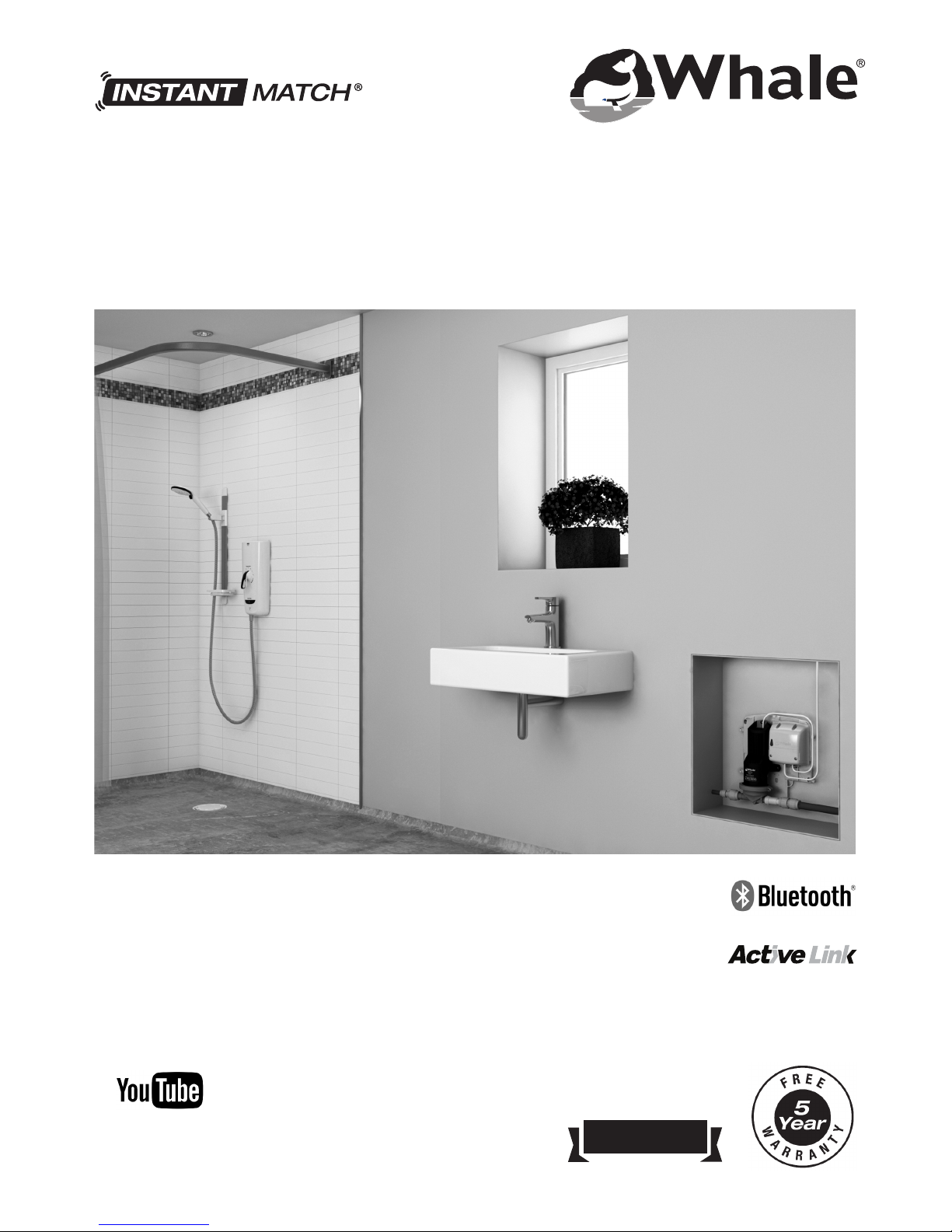
The front cover shows the product installation in an apartment with the components in a concealed access.
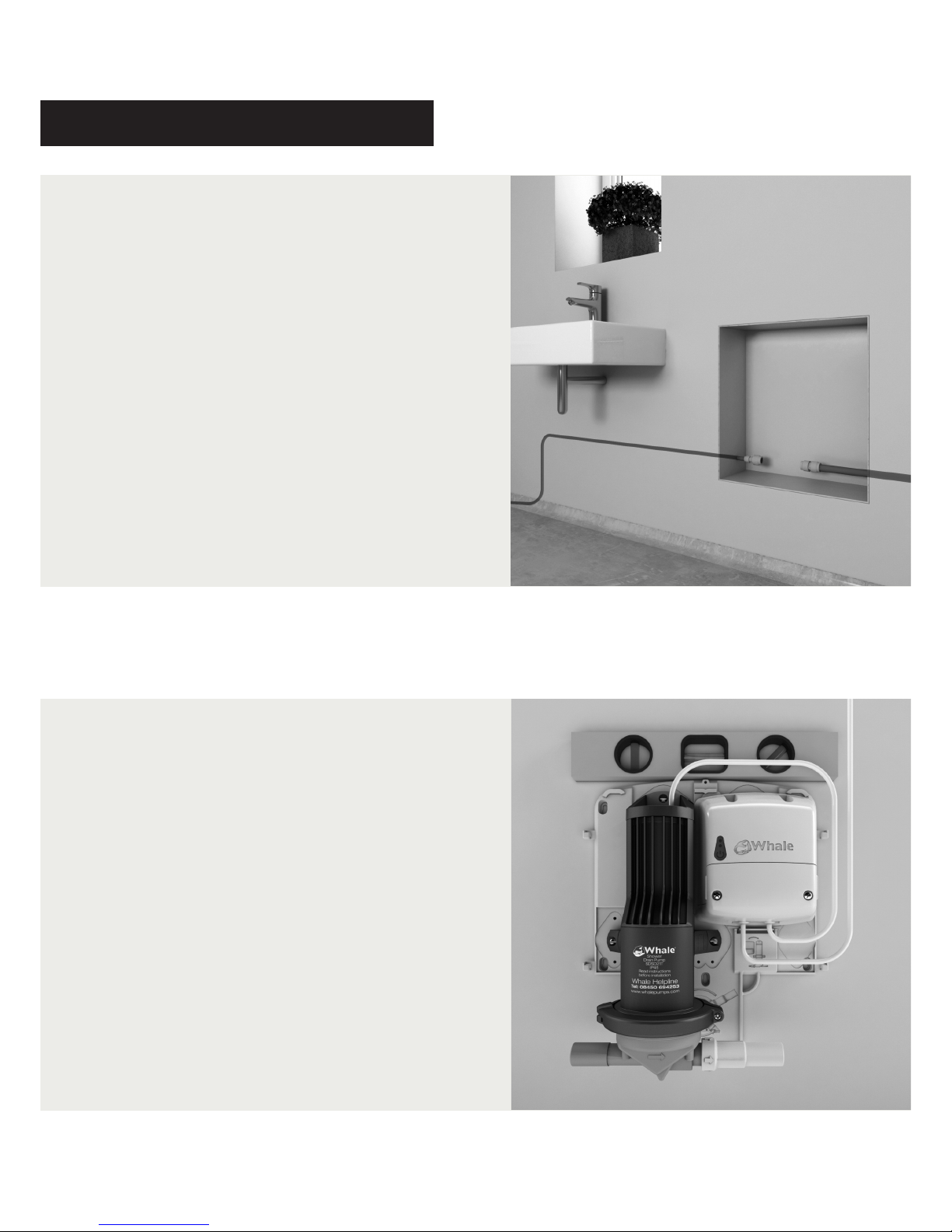
Assess your installation prior to fitting to ensure that the unit will be situated in an accessible location.
Typical installations would have these components in an adjacent cupboard i.e. airing cupboard or in a false
wall with an access panel. Do not fit the pump cover in these locations.
Incorrect installation may invalidate the warranty.
Principles of Operation
This kit has been designed for the pumping of shower waste water. The Whale Instant Match® with Bluetooth® wireless
technology control unit uses the flow signal from the shower to measure the flow rate of water into the shower. The
control unit uses the signals sent from the flow sensor to adjust the pump speed to match the flow of water from the
shower. This minimises suction noise at the gulley. When the shower is turned off, the flow sensor sends a signal to
the control unit and after a pre-set time delay the pump turns off. After a further 15 minutes the pump will automatically
switch on for a short period of time at a reduced pumping speed, removing any run off water pooled in the shower area.
The pump has the ability to run dry without causing damage. Non-return valves in the pump head prevent smells
entering the bathroom area from the waste pipe.
Installation Warnings
Before installation please read the instructions. All electrical and mechanical components (transformer and pump) must
be accessible after installation.
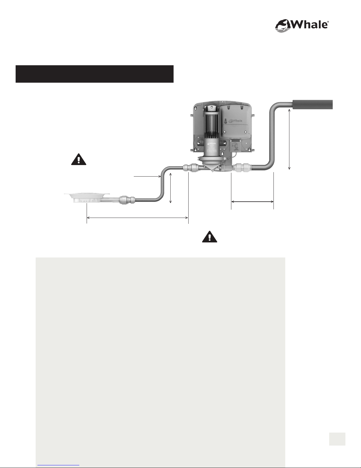
• The Whale Instant Match® with Bluetooth® wireless technology is designed to work on shower bases with a minimum
of a 1:40 fall to the gulley. Where the fall is insufficient, the water will not refill the gulley rapidly enough and so suction
noise will be increased. We recommend the use of a shower former as this eliminates the risks of pooling caused by
insufficient fall to the gulley.
• Forming a shower base by hand is a highly skilled task and should be carried out by a trained installer. Do not
attempt this if you are unsure and seek professional advice.
• The maximum flow rate of the shower that the pump is designed to work with is 8 ltrs/min.
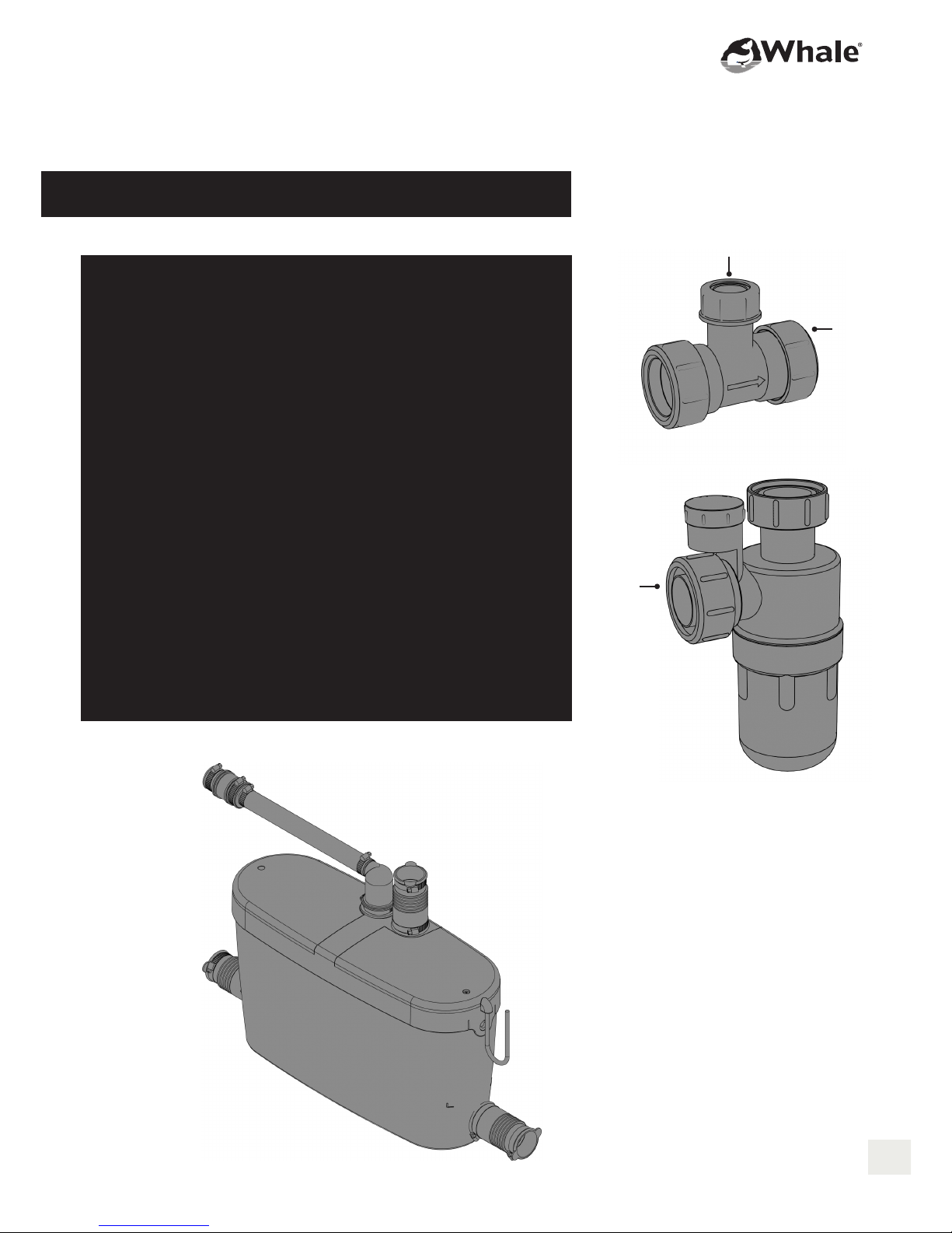
• Avoid plumbing the pump outlet into the waste piping that other appliances drain into as there is a risk of
induced syphoning. Use an anti-syphon trap in these situations. (See page 7)
• In installations where the floor is being formed in the screed, we recommend the following minimum falls:
40mm in 1m, 20mm in 500cm,10mm in 250cm.
• Plumbing must comply to latest WRAS standards.
• The electrical wiring must conform to EU wiring regulations BS7671:2008 Part 7 (17th Edition).
• Pipework must be secured to prevent vibration and noise.
• Ensure that the water fall from the shower head is as close to the gulley as possible.
WARNING
3

lumbing of the Waste Pipe
User warnings 2
End user help 2
Principles of operation 3
Plumbing specication 5
Plumbing gulley 6
Plumbing of waste pipe 7
Installation 8
Transformer settings 11
Bluetooth®wireless technology setup 12
Bluetooth®wireless technology unpairing 15
Hardwired setup 16
Purge cycle 18
Swapping pump & transformer on backplate 18
Safety warning 18
Installation testing and repair 19
EU declaration of conformity 20
Statement of limited warranty 20
Specication 21
List of parts included in the kit 22
Spare and Accessories 22
Fault diagnosis 24/25
Product dimensions 26/27
Index

Maximum pipe length is 3m
from gulley to pump. Pipe from
gulley to pump must be in 15mm.
MIN 1:40 FALL (Do not use 22mm pipework for
electric showers. This will increase gulley noise.)
GULLEY
3M (MAX)
TRAY
15MM DIA PIPE
USE ONLY 22MM
PIPE ON THE
PUMP OUTLET
0.2 M (MIN)
0.4 M (MAX)
FORMED
BEND
1M (MAX)
WASTE PIPE
HORIZONTAL TO WASTE PIPE
TO INCREASE PUMP LIFE ENSURE THAT 32mm ( 1 1/4")
or 40mm (1 1/2") PIPE IS USED WITH A GRAVITY
FALL WHERE THE PIPE LENGTH IS GREATER THAN 1M.
IF LESS THAN 1M USE 22MM PIPE
WARNING
WARNING
• The Whale®pump is IP45 compliant. Locate pump in
accordance with BS7671: 2008 Part 7 (17th Edition).
The pump may be installed in bathroom zones 1, 2 or 3.
• Maximum flow rate 8 ltrs per min.
• Unit and Flow Sensors MUST BE ACCESSIBLE AFTE INSTALLATION.
• Use slow radius bends where possible. Full size elbows are acceptable,
not stem or Male/Female elbows. Where possible avoid attaching elbows
directly to the pump.
• Inserts MUST NOT be used with plastic pipe.
• Please use the push fit fittings supplied with the kit. Ensure the pipe
is pushed fully home into the fittings and secured by the 'twist lock'.
Use silicon spray to aid pipe insertion in order to prevent the 'O' ring
being displaced or rolled.
• Ensure pipe edges are score free. Do not use a hacksaw to cut pipe.
• Use one vertical lift to the pump and one vertical rise from the pump.
Pipework must be secured.
0.5 M
(MAX)
5
Fig 1.1
Plumbing Specification

umbing of the Waste Pipe
• Rotate the pump head if necessary. Loosen clamping ring screw,
rotate and retighten as shown. See Fig 1.2
• Before commissioning the shower and running water through the
system, ensure that the shower area and gulley are completely free
of building debris, especially tile grout, screed material and latex.
Plumbing Gulley
• Do not use inserts or stem elbows as these restrict flow.
• When fitting in solid floors if copper pipe is used, it must be
sheathed to prevent corrosion.
• Orientate gulley so that it exits towards the pump inlet to avoid
unnecessary bends.
Wet Floor Gulley:
The wet floor gulley has a 40mm profile to enable it to fit into a screed
floor without penetrating the damp-proof membrane. See Fig 1.3
• Where a floor former is not used, the gulley has two lugs either side of
the discharge pipe to enable the gulley to be fixed to the floor whilst
screed is laid.
• Where a floor former is used, these lugs can be easily broken off to
enable it to be fitted.
• The gulley has a conventional clamping ring to accommodate vinyl
flooring.
• Once the area has been cleaned and before the shower is lined,
remove dust seal and click cover into place.
Tray Gulley:
The tray gulley has a 35mm profile to enable it to fit into a screed floor
without penetrating the damp-proof membrane. See Fig 1.4
• Use the hand tool provided to tighten the locking flange and leave it in
place to keep debris out of gulley. Only remove it and fit the gulley cover
when the shower area has been cleaned. See Fig 1.4
• Ensure that the gulley debris grid provided is fitted before the shower
is used. See Fig 1.4
Fig 1.2
Fig 1.3
Fig 1.4

Plumbing of the Waste Pipe
The outlet of the pump can be connected into the waste
pipe, e.g. existing bath waste. Black rubber fittings are
provided for this.
• In confined bathrooms the pump discharge may go into
the sink waste pipe using suitable adaptors. See Fig 1.5
for 32mm (1 1/4") McAlpine examples and the McAlpine
catalogue for other variants.
Use with a Macerator Pump
• Discharge from the Whale®pump must go into the top
of the macerator box. Do not use the bottom entries.
See Fig 1.6
• It is preferable to have two separate discharge lines to
waste as any failure of the macerator will not be
detected by the Whale pump.
Fig 1.6
Fig 1.5
22mm
V33T
32mm
(1 1/4")
A10V
32mm
(1 1/4")
Macerator Pump
7

• Run 15mm pipe from gulley to pump inlet (max 3m).
• Use slow radius bends where possible. Full size elbows
are acceptable, not stem or Male/Female elbows. Where
possible avoid attaching elbows directly to the pump.
2. Locating your pump on the wall
• Select a suitable location for the pump, considering
the best plumbing option for the pump outlet to
discharge into the waste pipe. The pump head may
be rotated to the left hand side or right hand side.
• Mount square to wall.
• Using a spirit level ensure that the unit is mounted level.
• Do not install the pump inlet/outlet more than
500mm off the floor.
• NOTE: The pump and transformer mounting location
on the backplate may be swapped right to left / left to
right. See Page 18 for further information.
1. Plumbing drainage pipe
Plumbing of the Waste Pipe
Installation

• Mark the hole centres through unit backplate.
• Drill holes in wall and fit wall plugs (if necessary).
Use 6mm masonry bit.
• Secure the backplate to the wall using
supplied screws.
• Use screw locations 1,2,3. Locations A and B
are optional.
3. ounting your pump to the wall
• Push the pipes into the fittings to the full depth of
insertion and secure by locking the fittings using
the "twist lock".
4. Plumbing connections
9
B
A

• Connect mains wire to a 5A fused spur.
• The transformer is factory set as shown to the right on
the jumper settings for Bluetooth®wireless technology
10 seconds overrun and 15mm inlet pipe size.
For other settings please refer to Transformer settings
(see page 11).
• Refit the hatch and tighten the screws to make
the transformer water resistant.
5. Wiring your transformer
• The blue LED flashes every 10 seconds indicating
that power is on.
• The green LED flashes when water is flowing
through the shower.
• When the test button is depressed the buzzer beeps.
6. The Whale Instant atch® with Bluetooth®
wireless technology transformer includes
Activelink diagnostics to aid installation:
On the transformer are two indicator LEDs
WITH

The transformer is factory set for use in Bluetooth® wireless
technology mode with a 10 second overrun and 15mm Inlet
pipe diameter. Other settings are given below:
9. Transformer settings
Flow Sensor Type:
1 Aux
2 Sika
3 Gems 1000ppl (pulses per litre)
4 Gems 2200ppl
5 Venturi
6 Mira Wired
7 Bluetooth
Off Delay
10s
30s
60s
Pipe Inlet
Diameter
1ᴓ/ 15mm inlet pipe
(for electric showers only)
2ᴓ/ 22mm inlet pipe
(for mixer showers)
8. Optional external
pump over run switch
Use a retractive switch to briefly activate the pump.
This facility is for use when the wet area is being cleaned,
or for ritual cleansing. The pump will run for 15 seconds at
full speed to clear any water in the showering area.
The retractive switch shown is available from Screwfix.
(Retractive Switch 1 Gang 1 Way Part No. 6151 )
NOTE: This switch may only be fitted outside the wet area.
11
7. Fit and secure pump cover
when required to complete set up

Important Information
Please read the following information before setting up a Bluetooth®wireless technology connection between
the Whale Instant®Match with Bluetooth® wireless technology transformer and Mira Advance ( 09N) shower:
• The Bluetooth®function of the Whale Instant Match®transformer will only work with the Mira Advanced Flex
Extra ( 09N) shower. Previous Whale Instant Match®Wireless transformers cannot be connected wirelessly
to the Bluetooth® wireless technology enabled Mira Advance shower®.
• Bluetooth® wireless technology enabled transformers can be easily identified by the blue test button.
• For optimum signal strength mount the transformer within 5 meters of the shower.
• Locating the transformer outside of a 5 meter radius can cause a communication breakdown between
the transformer and shower, resulting in intermittent or complete failure to operate.
• Be aware that in very rare situations dense building material, metallic objects such as steel baths and
foil lined plaster board, or electronic devices may interfere with the Bluetooth® wireless technology signal
and result in intermittent failure. In this situation you should relocate the transformer closer to the shower.
• A hardwired connection should be established if a Bluetooth® wireless technology connection cannot be
made between the shower and transformer.
• If any components or cords are damaged, it must be replaced by a qualified person to avoid a hazard.
Set up
1. Shower settings
• Before beginning the Bluetooth registration process
please ensure that the “Pump LK2 switch inside the Mira
Advance ( 09N) has been set to the “ON position as per
the diagram shown.
• At this stage please ensure that your transformer is set to be
used with Bluetooth® wireless technology: the flow sensor
setting should be set to 7 for “Bluetooth” and the pipe inlet
diameter should be set to 1 for 15mm.
12345678
BEAB
OFF ON
43 DEG C
45 DEG C
RESERVED
6L/MIN
PUMP LK3
PUMP LK2
PUMP LK1
WARNING
Plumbing of the Waste Pipe
Bluetooth®wireless technology

• Ensure that the electric supply to the shower
is turned OFF. Then turn the dial on the
shower to FULL COLD.
3. Shower set up
2. Transformer set up
• Switch the mains electric supply to the transformer ON.
The light on the transformer will now flash red to indicate
that a Bluetooth® wireless technology connection has not
yet been established.
• Press and hold the blue test button on the transformer until
the the light flashes red and green to indicate that the
transformer is now in pairing mode.
NOTE: You now have 120 seconds to pair the
transformer to the shower.
13
• Switch the mains electric supply to the shower ON.
• Within 10 seconds press and hold the Start/Stop button on
the shower. Until the Start/Stop light on the button goes off.
4. Configuring the shower

6. Pairing the shower to the Whale
Instant atch® transformer
• Press and release the start/stop button on the shower.
The status light on the shower will now flash blue to
indicate that the shower is in pairing mode.
• The status light on the shower will then flash white to indicate
that the transformer has successfully been paired to the shower.
• The Whale transformer will flash green only to indicate that it is
paired to the Mira shower
• Turn the temperature control to full cold and press the
Start/Stop button on the shower. The shower will now
return to normal standby mode.
• You may now follow the “Post Installation Procedure”
in the Mira®Advance Flex Extra Instruction Manual
(page 25) if necessary.
7. Completing the pairing
5. Slowly turn the dial on the
shower to position 2.

15
Some service work that may need to be carried out on the Mira®Advance Flex Extra ( 09N) shower
e.g. the renewal of the control PCB board may require the Bluetooth® wireless technology connection
between the shower and Whale Instant Match®transformer to be terminated and paired again once
the work has been completed. To unpair the transformer from the shower, please follow these steps.
1. Switch the mains electric
supply to the shower OFF.
2. Be sure to leave the mains electric
supply to the pump ON.The light on
the transformer will flash blue.
Plumbing of the Waste Pipe
Bluetooth® wireless technology Unpairing
3. Press and hold the test button on the
transformer until the light flashes red.
The transformer and shower have
now been unpaired.
NOTE: To pair the shower to the transformer again, please
follow the Bluetooth® wireless technology setup procedure.

Plumbing of the Waste Pipe
Hardwired Set Up
• Please ensure that the “Pump LK1” switch inside the Mira
Advance ( 09N) has been set to the “OFF” position as per
the diagram shown.
NOTE: Switch settings for other Whale transformers can be
found on page 17.
2. Shower Settings
1. Whale Instant atch®Transformer
(SDS236T) set up
Connect the signal wire to the left hand side signal block as
shown +Red ~Brown ⬇Black
• Ensure that that your transformer is set to be used with a
hardwire connection: the flow sensor setting should be set to
6 for “Mira Wired” and the pipe inlet diameter should be set
to 1 for 15mm.
Set up
The Whale Instant Match®transformer (SDS236T) can be
connected to the Mira Advanced Flex Extra ( 09N) shower
by means of a hard wired connection.

17
3. Connecting to the ira®Advance
Flex Extra (J09N) shower
From Transformer
TERMINAL BLOCK
NL
Brown
CN13
Black
Red
4. Connecting to the ira®Advance
Flex Extra (J09N) shower to other
Whale®transformers
Older models of Whale transformer can be connected to the
Mira®Advance Flex Extra ( 09N) shower. This table shows the
"LK" setting that the shower should be set to in order for the
pump to operate correctly when using the listed transformer.
• Connect the signal cable from the 755.678 transformer to
the shower, working from left to right as shown:
Brown, Red, and Black.
• Switch the mains electric supply to the transformer
and shower on. The pump will now operate when
the shower is activated.
Drain Pump
Type
755.199
755.210
755.299
755.349
755.399
755.449
755.549
Shower
Advance
Control PCB
LK1 - ON
LK1 - ON
LK1 - OFF
LK1 - OFF
LK1 - OFF
LK1 - OFF
LK1 - OFF
Signal
Hardwired
Hardwired
Hardwired
Hardwired
Hardwired
Hardwired
Hardwired/
Wireless

• The transformer is for indoor use only.
• The transformer contains no user serviceable parts.
• External components for service are jumper settings only.
• Where there is damage to the transformer or cabling,
contact your Whale distributor for a replacement.
• Do not connect mains power to the pump as this will cause permanent
damage and will result in an electrical hazard.
• Installation must conform to BS7671:2008 Part 7 (17th Edition).
• After 15 minutes the transformer will reactivate the
pump for 30 seconds at a lower flow rate to remove
any run-off or condensation that has collected in the
gulley to leave the shower area dry.
Swapping the mounting location of the
pump and transformer on the backplate
• Unscrew pump from base.
• Remove the transformer from its secure mounting
by pressing the securing tab on bottom of transformer.
• Move transformer to opposite side of the casing and
place the top two lugs into the spaces provided.
• Click the bottom part of the transformer into place
using the securing clip.
• Replace pump in new location and secure with screws.
Safety Warning WARNING
Purge Cycle

Installation Testing & Repair
The pump system is designed not to require maintenance. If
the pump runs but water builds up in the tray, first establish
the nature of the problem by following the following procedure.
This must only be carried out by a qualified contractor.
TEST PUMP SUCTION - Remove the pump inlet coupling
and press the test button to start the pump. Place a
finger in the inlet hole and sense how much the pump is
sucking. If strong suction is felt, examine the installation
and clear the blockage or check for air leaks as follows.
RODDING PIPEWORK - When a blockage is apparent,
disconnect the pump from the waste pipe, insert and attempt
to push the blockage through the pipe with a separate piece
of pipe size smaller than that installed. For example, to rod a
15mm pipe use a 10mm pipe as your rod to clear blockage,
and likewise for a 22mm pipe use a 15mm rod. This is an
effective way of ensuring any blockage is removed from the
waste pipe run. An alternative option for a rod is a 6mm drain
rodding spring if one is available.
EXTERNAL PIPEWORK TEST - Make up external pipe work
from the pump directly across the bathroom floor and elbow
into the gulley. Use elbows as required and up to 3m of pipe.
See Fig1.7. Turn the shower on. If water is removed from the
tray, then the issue exists in the pipework between the gulley
and the pump.
AIR LEAK TEST - Run a clear tube from the discharge to the
sink. If water builds up and fills the gulley, yet air is seen in the
clear tube on discharge, then the air must be coming from the
pipe work. Check and secure all above floor fittings. If these
are eliminated investigate the underfloor pipe work by lifting the
floor/tray. See Fig 1.7
FLOW RATE TESTING - A convenient way to measure the
flow rate is to get a 2ltr plastic jug and mark the 2ltr level in
black pen. Turn the shower on to where the customer
normally uses it - often maximum setting.
Put the jug under the shower head and measure how long it
takes for the jug to fill to the 2ltr line.
Longer than 20 seconds indicates flow rate of less than 6ltrs
per minute - typical for electric showers.
Shorter than 15 seconds indicates a flow rate of more than
8ltrs per minute - normal for mixers.
CHECK TRICUSPID VALVE - Remove the tricuspid valve
holder screwed onto the pump discharge. Remove the rubber
valve and assess its condition. If it is worn or stiff then change
and re-test. It is good practice to replace the tricuspid valve
when doing any routine service.
CHECK INSIDE PUMP HEAD - Remove the clamping ring
and pump head carefully so as not to disturb the seating of
the diaphragm. Check that the valves in the pump head are
clear of debris. Remove any debris and rinse out the pump
head before refitting the pump head and clamping ring.
Ensure that the diaphragm bead is not pinched, as this will
cause poor pump performance.
If the diaphragm has become unseated, disconnect one low
voltage lead at the pump, press the test button and briefly
touch the disconnected leads together. This will change the
position of the diaphragm. Do this until the diaphragm is at its
lowest position. The diaphragm bead will now push easily into
the groove on the pump body and the head will also fit easily
onto the diaphragm bead without pinching it. Then refit and
tighten clamping ring. Check for leaks whilst pump is running.
Spare parts and accessories are listed on Page 22.
Scan here to visit
our troubleshooting
YouTube site 19
Fig 1.7
www.youtube.com/WhaleHealthcare

Description of Equipment: Shower Drain System
We hereby declare, under our sole responsibility, that the
above product complies with the provisions of the following
EU Directives.
2014/53/EU RED Directive
2014/35/EU Low Voltage Directive
2014/30/EU Electromagnetic Compatibility Directive
Standards applied:
IEC 60335-2-41:2012 Edition 4
IEC 60335-1:2010+AMD1:2013 edition 5.1
EN 60335 2 41:2003 + A1:2004 + A2:2010
EN 60335 1:2012
EMC:
BS EN 55014-1:2006 + A2:2011
BS EN 55014-2:2015
BS EN 61000-3-2:2014
BS EN 61000-3-3:2013
Radio:
EN 301 489-3 v2.1.0
Richard Bovill
Engineering Director
Whale 2 Enterprise Road, Bangor,
Co. Down, BT19 7TA, UK
Technical Helpline: 0845 0694 253
whalepumps.com
info@whalepumps.com
tel: +44 (0)28 9127 0531
The products manufactured and supplied by the Company (“Products”),
are warranted to be free from material defects in design, workmanship and
material under normal use (“Defects”) for (unless otherwise extended in
advance in writing by the Company) a period of 3 years from date of purchase,
save that this warranty shall not apply where the Defect is attributable to
defective materials supplied by third parties. In such event, the only remedy
of the buyer of the Products (“Buyer”) will be against that third party.
This warranty applies only to Products that are properly installed and used in
accordance with all oral and written maintenance, installation, and operation
instructions provided by the Company. The Company shall not be liable for a
breach of any of the warranties in this Statement of Limited Warranty if the
Buyer makes any further use of the Products after giving the Company notice
of any Defect or the Buyer alters or repairs such Products without the written
consent of the Company. Products that have been disassembled or modified
(without prior written approval of the Company), are not covered by this
warranty. All Products are covered by a 3 year limited warranty (detailed
below) from (unless otherwise extended in advance in writing by the
Company) date of purchase (“Standard Warranty”).
In addition to the Standard Warranty, these Products will be covered by a
further warranty of 2 years but only when the registration form is completed
and returned (“Additional Warranty”). The period of such Additional Warranty
shall commence automatically the date the Standard Warranty expires.
In the event that any of the warranties offered by the Company are breached,
the Company shall (at its discretion) repair, replace or issue a spares kit for
the defective Product subject to prior examination at Company premises.
If the Company complies with this paragraph, it shall have no further liability
for a breach of the warranties in respect of such Products. Adjustment or
replacement of defective parts made under this warranty will not extend the
warranty period applicable either under the Standard Warranty and/or the
Additional Warranty.
The Company shall not bear any costs of removal, installation, transportation,
or other charges that may arise in connection with a warranty claim by the
Buyer. Such costs shall be the Buyer’s sole responsibility.
No claim in respect of defective Products will be valid unless the alleged
defective Products are returned at the Buyer’s expense to the Company
for inspection, together with proof of purchase.
EU Declaration of Conformity
Plumbing of the Waste Pipe
Statement of Limited Warranty
Table of contents
Other Whale Accessories manuals