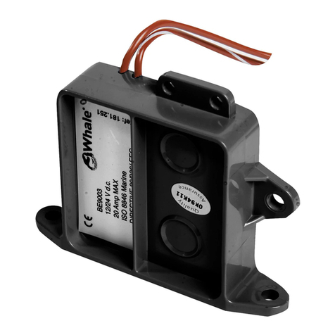
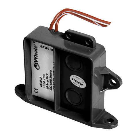
Whale BE9003 User manual

BE9003(B) / BE9006(B)
Automatic Switch with Electric Field Sensor Technology
Model Number Description
BE9003(B) Automatic Switch with Electric Field Sensor
Technology
BE9006(B) Automatic Switch with Electric Field Sensor
Technology - 30 second delay
Note: B suffix refers to bulk items. Minimum order quantities may apply.

Thank you for purchasing this Whale® product. For over 60 years Whale® has led the way in the design and
manufacture of freshwater and waste systems including - plumbing, faucets, showers and pumps for low voltage
applications. The company and its products have built a reputation for quality, reliability and innovation backed up by
excellent customer service.
1. SPECIFICATION 4. TO THE USER 7. INSTALLATION 10. PATENTS AND TRADEMARKS
2. LIST OF CONTENTS 5. APPLICATION 8. MAINTENANCE 11. WARRANTY
3. TO THE FITTER 6. WARNINGS 9. SERVICE SUPPORT 12. DECLARATION OF CONFORMITY
Check that the product is suitable for the intended application, follow installation instructions and ensure all relevant
personnel read the points listed below. Also ensure these instructions are passed on to the end user.
Read the following instructions carefully.
WARNING: Please note that incorrect installation may invalidate the warranty.
This Whale® Electric Field Sensor senses water level and automatically controls a 12 or 24 volt bilge pump. The switch
turns on when it senses 51mm (2") water level and turns off when water is below 13mm (1/2"). This product is designed for
use in pleasure boat applications, and is not intended to be used in commercial boating applications or for any other use.
With all applications, it is important that a system of safe working practice is applied to installation, use and
maintenance. Ensure the electric supply is turned off and waste water system is drained before installation
1. Not suitable for use with flammable liquids, diesel, chemicals etc.
2. Suitable for only freshwater or bilge water. If it is intended for any other purpose or with any other liquid,
it is the users responsibility to ensure that the switch is suitable for the intended use and, in particular,
that the materials are fully compatible with the liquids to be used.
3. Failure to fuse and connect wires according to these instructions will void product warranty and may cause damage
or serious injury.
4. Connect in-line fuse (Note: Fit the appropriate amperage specified for your pump model).
5. Correct voltage range is 10.5 V d.c. to 28.8 V d.c. DO NOT use with other voltage, or with A.C., or A.C.to D.C.
converted power sources.
6. The Electric Field Sensor may draw up to a maximum of 20 amps.
7. NOTE - Maximum operating temperature ~ 60°. Maximum flash temperature ~ 90°.
7.1 Location
1. Mount the switch vertically as shown in fig. 1 (wires located uppermost). Locate the switch as close to the pump
as possible to ensure the same water level.
2. Prepare a mounting block. Do not fasten switch directly to the hull. Mounting block should be minimum 10mm
(3/8") thick marine plywood epoxied to the hull.
3. Switch base may be located up to 6mm (1/4") higher, but NEVER located lower than base of the pump.
7.2 Mounting
1. Use switch base (Fig. 1) or mounting ears (Fig. 2) as a
template to mark pilot holes in mounting block.
2. Set drill depth gauge to avoid drilling through hull. Drill
two 3mm (1/8") diameter pilot holes.
3. Fasten switch onto mounting block with #8 x 1/2"
(3.5mm diameter x 13mm) stainless steel screws (not
supplied).
1. SPECIFICATION
Model Number BE9003(B) BE9006(B) (with 30 second time delay)
Voltage 12 V d.c. or 24 V d.c.
Current Suitable for up to 20 Amps
Residual Current 0.008 Amp
Recommended Circuit Breaker Maximum - 20 Amps (Exact circuit breaker rating should be rated in line with the
installed pump - see pump installation manual)
3. TO THE FITTER
4. TO THE USER
5. APPLICATION
6. WARNINGS
2. LIST OF CONTENTS
7. INSTALLATION
Fig 1 Using Switch Base Fig 2 Using Mounting Ears
INSTRUCTION AND INSTALLATION MANUAL

7.3 Wiring
WARNING: Fire hazard. Wiring must comply with applicable electrical standards and include a properly rated circuit breaker
(Fuse rating must be rated for the pump used in the system. Check the pump installation manual for the specific fuse size).
WARNING: Improper wiring can cause a fire resulting in injury or death.
NOTE: Switch off the power prior to making connections. Suggested wiring information is given as a guide only. For full
information, refer to the USCG, ABYC and ISO regulations for marine applications and wiring gauges, connectors and fuse
protection.
1. Follow the wiring diagram (Fig 3). All fuses and the circuit breaker must be properly rated for the bilge pump
within the circuit (see pump instruction manual for guidance). The maximum circuit breaker must be is 20 Amps.
NOTE: Do not use thermal circuit breakers with the BE9003(B)/BE9006(B). Magnetic breakers must be used.
2. The wiring is as follows:
•Manual terminal directly to
brown (+) pump wire.
•Automatic terminal to switch
brown/white stripe (+)
• Switch brown (-) to pump
brown (+).
•Black (-) pump wire to
negative battery terminal
3. Make all wiring connections above highest water level, using permanent waterproof terminals. Coat terminals with
liquid electrical tape.
7.4 Testing
1. After installation, hold fingers for 10 seconds on two raised circles on switch face.
• If wiring is correct, pump activates.
• Remove top finger, pump stays on.
• Remove bottom finger, pump should turn off after a short delay.
NOTE: BE9006(B) has a longer override delay of 30 seconds past the 1/2” (13mm) OFF point.
2. Test with water in bilge to confirm that pump turns on and off properly. If not, reposition
the switch to allow for activation.
This Whale® Electric Field sensor is designed to only require minimal maintenance.
WARNING: Ensure that the switch is disconnected from electrics and thats the system is fully drained prior to maintenance.
For Optimal Performance
• Ensure the switch is clear of debris.
• Keep fuse and wiring connections high and dry.
Annual Checks
• Whale® advises that the vessel plumbing system is checked annually for leaks and obstructions. A full boat electrics
check by a marine electrician is also recommended.
• Whale® advises testing your switch as per section 7.4 on an annual basis.
Winterizing
Fully drain system for winterising. Failure to winterise your system may invalidate the product warranty.
Fig 3 - Wiring instructions
Brown / white stripes wire
Brown wire Test Circle
2” (51mm) ON
1/2” (13mm) OFF
Mounting Block
3/8” (10mm)
Waterproof Connector
Above Water Level
Magnetic
Circuit
Breaker
Brown Wire
Black Wire
Manual
Automatic
3 Way Switch
Off
12 to 24 V
d.c. Power
3/8” (10mm) min. Mounting Plate
Pump
Switch Wire Colour
Positive Brown/White
Stripes
Signal Out Brown
Fig 4 - Testing Switch
8. MAINTENANCE
Pump Fuse

Whale® is a registered trademark of Munster Simms Engineering Ltd, Bangor, Northern Ireland.
This product and the technology it uses are protected by US patent numbers - 5594222 / 6310611 / 6320282
This product complies with all relevant European directives and standards. Please contact Whale® if further details are
required.
Manufacturer’s Declaration - We hereby declare, under our sole responsibility, that the enclosed equipment complies with
the provisions of the following EC Directives.
94/25/EC amending 2003/44/EC - Recreational Craft Directive
2004/108/EC - EMC Directive
Based on the following harmonized standards
EN55022: 2006 + A1:2007 EMC Radiated Emissions
EN55014: 2006 + A1:2009 EMC Conducted Disturbance Power
EN55014: 1997 + A2:2008 EMC Immunity
CE mark affixed: 28/09/11
Basis on which conformity is declared
The above equipment complies with the protection requirements of the EMC Directive and the principal elements of the
safety objectives of the EC Directives.
Standards applied
EN 28846:1993 Ignition Protected
ISO 15083:2003 Bilge Pumping Systems
ISO 10133:2000 Extra Low Voltage d.c. Installations
12. DECLARATION OF CONFORMITY AND STANDARDS
10. PATENTS AND TRADEMARKS
Discover other boat plumbing on our website.
Other manuals for BE9003
1
This manual suits for next models
3
Table of contents
Other Whale Switch manuals
Popular Switch manuals by other brands

NETGEAR
NETGEAR Smart Switch GS752TXS Hardware installation guide

schmersal
schmersal AZM300B-I2-ST-1P2P-A-DU instructions

OEZ
OEZ PS-LT Instructions for use

SSS Siedle
SSS Siedle SSM 611?01 Product information

Endress+Hauser
Endress+Hauser Liquiphant FTL33 IO-Link Brief operating instructions

ATEN
ATEN KE6900 user manual