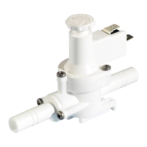
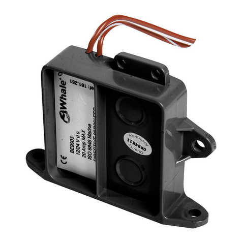
Whale WU7207 Assembly Instructions

In-Line Pressure Switch
WU7207 / WU7207B
INSTALLATION & USER INSTRUCTIONS
Thank you for purchasing this Whale® product.
For over 60 years Whale has led the way in the design and manufacturer of water and waste systems including:-
plumbing, faucets, showers, pumps and heating for low voltage applications. The company and its products have built
a reputation for quality, reliability and innovation backed up by excellent customer service.
For information on our full product range visit: www.whalepumps.com
Typical Installation
The Whale In-Line Pressure Switch is designed for use in freshwater pressure systems without micro-switches. It is
suitable for use with 12V d.c. or 24V d.c. Whale Submersible or Whale In-Line Pumps.
This product is designed for use with freshwater only. If it is intended for use with any other liquid, it is the user’s
responsibility to ensure that the materials are fully compatible with the liquids to be used and that a system of safe
working practice is applied to installation, use and maintenance.
CONTENTS
1. Principles of Operation
2. Application
3. Warnings
4. Instructions for Installation
5. Operating Instructions
6. Maintenance
7. Service Support Details
8. EU Declaration of Conformity
9. Warranty
The Whale In-Line Pressure Switch is designed to operate in freshwater pressurised systems connected to a 12V
d.c.or 24V d.c. power supply in recreational vehicles or vessels. The pressure switch detects the opening or closing of
any tap in the system and switches the pump on or off as required.
The Whale In-Line Pressure Switch is designed for use in freshwater pressurised systems, supplied by either a Whale
Submersible or Whale In-Line Pump.
Use for any other purpose or with any other liquid is not recommended and is entirely at the user’s risk.
Observe all warnings.
To the Fitter: Check that the product is suitable for the intended application, follow these installation instructions and
ensure all relevant personnel read the points listed below. Also ensure that these operating instructions are passed on
to the end user.
To the User: Please read the following carefully before installation and use.
1
LIST OF IMAGES
1. Pressure Switch Location
2. Connecting Microswitch Terminals
3. Installing Isolator Switch
1. PRINCIPLES OF OPERATION
2. APPLICATION
3. WARNINGS
4. INSTRUCTIONS FOR INSTALLATION

Before you begin, always disconnect power sources before installing or making connections with all applications. It is
important that a system of safe working practice is applied to the installation, use and maintenance. Always ensure the
water system is drained before commencing work.
Step 1 Choose a location to install the In-Line Pressure Switch. When choosing an installation location, you must
consider the following:-
i) The location must allow access to the pressure switch for adjustment and mainentance
when required.
ii) The pressure switch must be installed in the pipework, on the outlet side of the pump before
any T pieces. This means that the opening of any tap in the system will activate the pressure
switch.
iii) The pressure switch must be screwed to a surface or suspended in the pipework.
Figure 1: Pressure Switch Location
Step 2 Use Whale 12mm Quick Connect plumbing fittings (Whale Part Number: WU1202) to connect the pressure
switch to the pipework.
Step 3 Connect microswitch terminals as shown below.
Figure 2: Connecting Microswitch Terminals
Step 4 You must fit an isolator switch and a fuse (not provided) in the postive line, as shown below.
2
and
Figure 3: Installing Isolator Switch
To Outlets
From
Pump
Click x 2
Click x 2
Direction of Water Flow
Pressure adjusting screw
To Battery +ve via Isolation Switch and Fuse
To Pump +ve
To Pump +ve

Priming the System
Option 1: In-Line Pressure Switch Fitted With In-Line Pump
Option 2: In-Line Pressure Switch Fitted With Internal Submersible Pump
Option 3: In-Line Pressure Switch Fitted With External Submersible Pump
Option 1: In-Line Pressure Switch Fitted With In-Line Electric Pump
Step 1 Disconnect power supply at the isolator switch.
Step 2 Open one cold tap fully.
Step 3 Ensure that the storage tank is filled to a level higher than the pump.
Step 4 Turn the power back on at the isolator switch and close the tap once water is running.
Option 2: In-Line Pressure Switch Fitted With Internal Submersible Pump
Step 1 Ensure that there is no air trapped in the pump. Air is released by gently shaking the pump under water while
the pump is in the water tank is switched off. Trapped air in the submersible will not allow the pump to prime.
Option 3: In-Line Pressure Switch Fitted With External Submersible Pump
Step 1 The pump must be placed in the water before connecting to the side of the vehicle.
Please note: At normal flow rates the pump should operate continuously - but at low rates the pressure switch will
cycle on and off to maintain back pressure in the pipework.
Please note: When battery voltage is stable, the pump will produce steady water flow. If battery voltage decreases or
increases water flow will be intermittent and the pressure switch will turn on and off to maintain pressure in pipework.
3
5. INSTRUCTIONS FOR OPERATION
Setting the Pressure Switch
Your pressure switch is factory set and should not normally require adjustment. However, adjustment may be required
if the power supply voltage has varied from the previous setting, either due to battery drainage or higher voltage
being supplied when the battery charger is operating. In the event that your pump doesn’t switch off when you close
the taps, or it pulses on and off rapidly when the taps are fully open, follow these guidelines to re-adjust the pressure
switch setting.
Step 1 Ensure the system, (including the Water Heater, if installed) is full of water and all taps are closed.
Step 2 Tighten the adjusting screw clockwise until the pump comes on (see Fig. 2).
Step 3 Open any tap until you have a smooth flow of water, then close the tap.
Step 4 Return to the pressure switch and turn the pressure switch adjustment screw slowly anti-clockwise until the
pump has stopped. Turn the adjustment screw a further half turn (180 degrees) anti-clockwise.
Step 5 Check for correct operation by opening and closing all taps individually. The pump should turn on when the
cold tap is opened and switch off immediately when the cold tap is closed. There will normally be some pulsations at
low flows. Please note: The hot side (if applicable) may take up to 10 secionds to react.
Three Golden Rules:
1. Never allow the pump to run dry.
2. Never allow the pump to run continuously for more than 15 minutes.

4
Declaration Number: EU-COMP1001-00
We the undersigned:
Name of Manufacturer: Munster Simms Engineering Ltd
Address: 2 Enterprise Road, Bangor, Co. Down, BT19 7TA
Country: Northern Ireland
Hereby we declare that the products listed below, which are in contact with drinking water from delivery date January
1st 2016, fulfil the requirements of the state of the art. In particular the mentioned plastic parts, which are in contact
with drinking water, are tested according to the Guidelines of the Ministry of Health and Environment (Guideline KTW)
and the technical rules of the DVGW (W270) and fulfil the microbiologic and chemical requirements for the use in
mobile drinking water installations. The metal parts used in these products, which are in contact with drinking water,
fulfil the requirements according to DIN 50930-6.
WU7207 (8) In-Line Pressure Switch
(B) suffix refers to items available only in bulked pack quantities for high volume production OEM use.
Reports for all the individual components, in contact with drinking water, are held in the above file number, at the
address shown.
Name and Position of Person binding the manufacturer or authorised representative:
Name: Richard Bovill
Function: Engineering Director
Location: Munster Simms Engineering Ltd
Date of Issue: 16th February 2016
8. EU DECLARATION OF CONFORMITY
Whale recommends regular inspection with maintenance and replacement of components as necessary.
Replacement components are available (Whale Part Number: AK7209).
For installation or serviceable parts advice please contact Whale Customer Support:
Tel: 00 44 (0)28 91 27 0531
6. MAINTENANCE
7. SERVICE SUPPORT DETAILS

5
This product is protected by a 1 year warranty, for full details of our warranty statement please see enclosed leaflet.
©Copyright Whale® 2018 - All rights reserved. Reproduction in whole or in part without permission is prohibited.
WHALE®, is a registered trademark of Munster Simms Engineering Limited, Bangor, Northern Ireland trading as
Whale. Whale’s policy is one of continuous improvement and we reserve the right to change specifications without
prior notice.Illustrations are for guidance purposes only.
Neither the accuracy nor completeness of the information contained in any Product brochure is guaranteed by the
Company and may be subject to change at its sole discretion.
Munster Simms Engineering Ltd.
2 Enterprise Road, Bangor, N. Ireland BT19 7TA
Tel: +44 (0)28 9127 0531
www.whalepumps.com
180.25_v3_0518_ammc_db
10. WARRANTY
Other manuals for WU7207
1
This manual suits for next models
1
Table of contents
Other Whale Switch manuals
Popular Switch manuals by other brands

ZyXEL Communications
ZyXEL Communications ES-2048 release note

Sitecom
Sitecom CN-5002 user manual

LQ GROUP
LQ GROUP 1162723-00000 instruction manual

GE
GE 70R-1000D Operation and maintenance manual

Alcatel-Lucent
Alcatel-Lucent OmniSwitch 6850-48 Getting started guide

Cisco
Cisco DS-C9216I-K9 Configuration guide