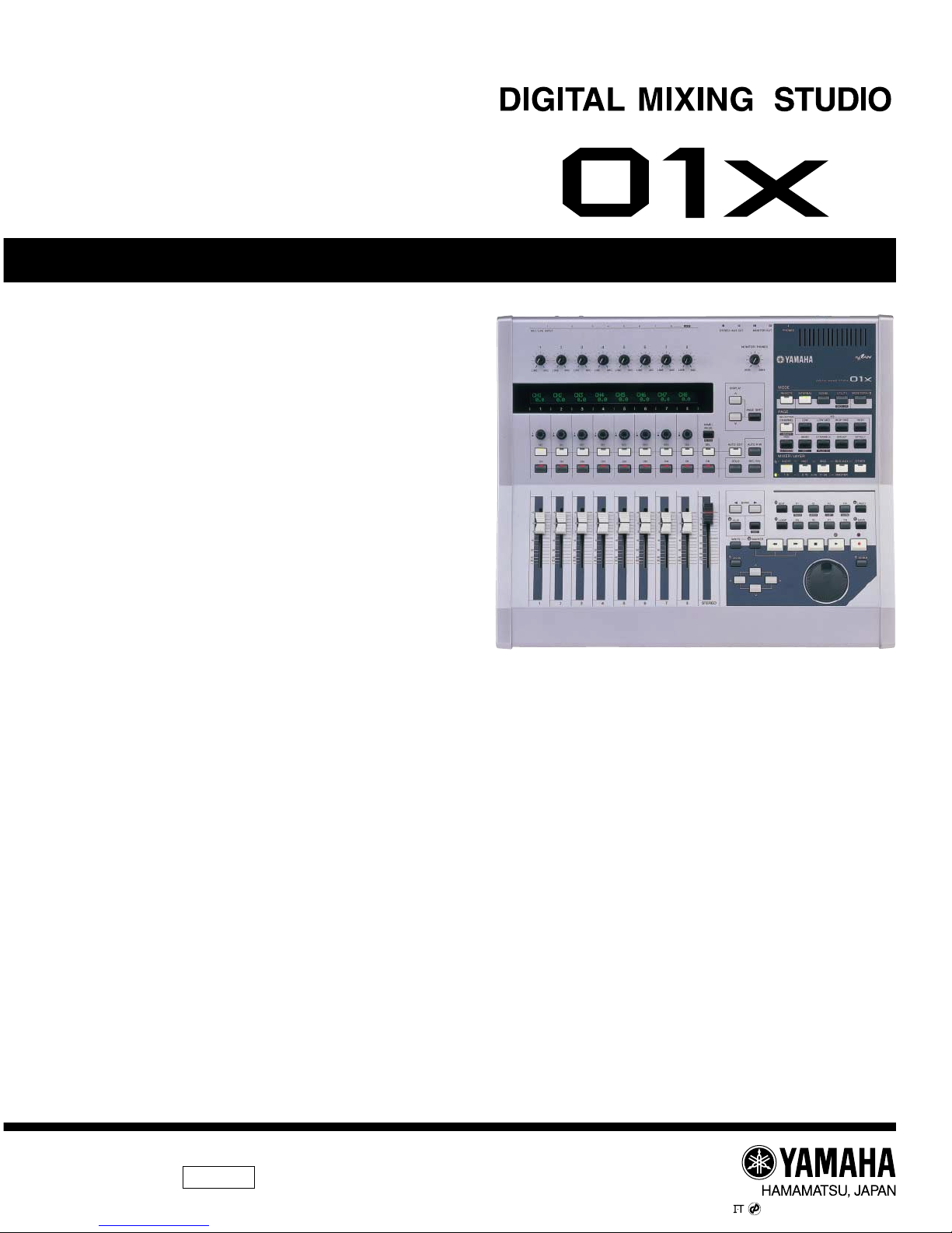
Yamaha 01x User manual

SERVICE MANUAL
■ CONTENTS(目次)
SPECIFICATIONS(仕様)....................................................................... 3/5
DIMENSIONS(寸法図)...............................................................................7
PANEL LAYOUT(パネルレイアウト)........................................................8
CIRCUIT BOARD LAYOUT(ユニットレイアウト).............................. 12
DISASSEMBLY PROCEDURE(分解手順)........................................... 13
LSI PIN DESCRIPTION(LSI端子機能表)............................................ 21
IC BLOCK DIAGRAM(ICブロック図).................................................. 33
CIRCUIT BOARDS(シート基板図)....................................................... 36
UPDATAING FIRMWARE(ファームウェアのアップデート)........52/54
INSPECTIONS(検査).........................................................................56/61
TEST PROGRAM(テストプログラム).............................................66/83
TROUBLE DIAGNOSIS(故障診断について).............................. 100/101
DISPLAY MESSAGES(ディスプレイメッセージ).................... 102/103
ABOUT CONNECTIONS WITH EXTERNAL DEVICES WHEN USING
THE O1X WITH A COMPUTER..................................................... 104
MIDI IMPLEMENTATION CHART .................................................. 105
MIDI DATA FORMAT ...................................................................... 106
PARTS LIST
BLOCK DIAGRAM(ブロックダイアグラム)
OVERALL CONNECTOR CIRCUIT DIAGRAM
(総コネクタ接続回路図)
OVERALL CIRCUIT DIAGRAM(総回路図)
Copyright (c) Yamaha Corporation.All rights reserved.PDF-K8542 Printed in Japan ’04.01
SY 011705
20031125-179000

2
O1X
IMPORTANT NOTICE
This manual has been provided for the use of authorizedYamaha Retailers and their service personnel.It has been assumed
that basic service procedures inherent to the industry, and more specifically Yamaha Products, are already known and
understood by the users, and have therefore not been restated.
WARNING : Failure to follow appropriate service and safety procedures when servicing this product may result in
personal injury, destruction of expensive components and failure of the product to perform as
specified. For these reasons, we advise allYamaha product owners that all service required should
be performed by an authorizedYamaha Retailer or the appointed service representative.
IMPORTANT : This presentation or sale of this manual to any individual or firm does not constitute authorization,
certification, recognition of any applicable technical capabilities, or establish a principal-agent
relationship of any form.
The data provided is believed to be accurate and applicable to the unit (s) indicated on the cover.The research engineering,
and service departments ofYamaha are continually striving to improveYamaha products. Modifications are, therefore,
inevitable and changes in specification are subject to change without notice or obligation to retrofit.Should any discrepancy
appear to exist, please contact the distributor’s Service Division.
WARNING : Static discharges can destroy expensive components. Discharge any static electricity your body
may have accumulated by grounding yourself to the ground bus in the unit (heavy gauge black wires
connect to this bus).
IMPORTANT : Turn the unit OFF during disassembly and parts replacement. Recheck all work before you apply
power to the unit.
WARNING : CHEMICAL CONTENT NOTICE !
The solder used in the production of this product contains LEAD. In addition, other electrical/electronic and/or plastic
(where applicable) components may also contain traces of chemicals found by the California Health and Welfare Agency
(and possibly other entities) to cause cancer and/or birth defects or other reproductive harm.
DO NOT PLACE SOLDER, ELECTRICAL/ELECTRONIC OR PLASTIC COMPONENTS IN YOUR MOUTH FOR ANY
REASON WHAT SO EVER!
Avoid prolonged, unprotected contact between solder and your skin! When soldering, do not inhale solder fumes or expose
eyes to solder/flux vapor!
If you come in contact with solder or components located inside the enclosure of this product, wash your hands before
handling food.
■WARNING
Components having special characteristics are marked Zand must be replaced with parts having specification equal to
those originally installed.
Z印の部品は、安全を維持するために重要な部品です。交換する場合は、安全のために必ず指定の部品をご使用ください。

3
O1X
■SPECIFICATIONS
■General Specifications
Sampling Frequency Internal, External Normal rate: 44.1 kHz (-10 %) – 48 kHz (+6 %)
Double rate:88.2 kHz (-10 %) – 96 kHz (+6 %)
Frequency Response
44.1 kHz, 48 kHz 20 Hz – 20 kHz 0 +1/-3dB, MIC/LINE IN to STEREO OUT (48 kHz)
88.2 kHz, 96 kHz 20 Hz – 40 kHz 0 +1/-3dB, MIC/LINE IN to STEREO OUT (96 kHz)
Total Harmonic Distortion Less than 0.02 % 1kHz, LINE IN to STEREO OUT
Dynamic Range 103 dB LINE IN to STEREO OUT
Noise level -105 dBV
Crosstalk 70 dB
DA converter 24 bit Linear, 128 times oversampling (44.1, 48 kHz)/64 times over sampling (88.2, 96 kHz)
AD converter 24 bit Linear, 128 times oversampling (44.1, 48 kHz)/64 times over sampling (88.2, 96 kHz)
Internal Signal Processing 32 bit (Accumulator 58 bit)
Interface Functions
mLAN Audio I/F 18 ch Input / 24 ch Output (44.1 kHz, 48 kHz),
10 ch Input / 16 ch Output (88.2 kHz, 96 kHz)
MIDI I/F 5 ports Input / 5 ports Output
(for DAW, MIDI-A, MIDI-B, Studio Manager and Program Change Control)
Mixer Functions 28 ch Digital Mixing (44.1, 48 kHz)/18 ch Digital Mixing (88.2, 96 kHz)
Input MIC/LINE Input 8 ch (with 1 channel switchable to HI-Z Input)
mLAN Input 16 ch (44.1 kHz, 48 kHz)/8ch (88.2 kHz, 96 kHz)
mLAN Monitor Input 2 ch (Stereo one system) is cascade-connected to the Monitor Out (Stereo Bus and Mix Balance
can be adjusted)
Stereo Input Stereo; two systems (combined use with Effect return) (44.1 kHz, 48 kHz)
Stereo one system (88.2 kHz, 96 kHz)
Digital Input Stereo; one system
Digital Cascade Input Stereo; one system is cascade-connected to the Stereo Bus (with attenuator)
Oscillator Sine (100 Hz, 1 kHz, 10 kHz) / Noise, 0 dB – -96 dB (1 dB step)
Can be output to Stereo Bus, Rec Bus, Aux 1 – 4
Output Stereo Bus 2 ch (Stereo one system)
Rec Bus 2 ch (Stereo one system)
Aux Bus 2 ch (Send 1, 2)
Effect Bus 2 ch (Sends 3, 4; combined use with Aux 3, 4)
Direct Output 24 ch (mLAN output from Input Module x 24) (44.1 kHz, 48 kHz) / 16 ch (88.2 kHz, 96 kHz)
Effector 2 units (43 preset types) (44.1 kHz, 48 kHz)/1 unit (88.2 kHz, 96 kHz)
Channel Module MIC/LINE Input
24 systems (A/D Input x 8 ch, mLAN Input x 16) (44.1 kHz, 48 kHz) / 16 systems (88.2 kHz, 96 kHz)
mLAN Input Attenuator, Phase, Insert, 4-Band EQ, Dynamics, Aux Send 1 – 4, Level, Pan
Stereo Input Two systems (44.1 kHz, 48 kHz)/One system (88.2 kHz, 96 kHz) Attenuator, Phase, 4-Band EQ,
Aux Send 1 – 4, Level, Pan
Output Module Stereo Output Attenuator, 4-Band EQ, Dynamics, Insert, Level, Pan balance
Rec Bus Output Dynamics, Insert, Level
Aux 1 – 4 Output Level
Number of memories Preset Area User Area
Scene Library 1 99
Channel Library 2 127
EQ Library 40 160
Dynamics Library 40 88
Effect 1/2 Library 43 85
Input Patch Library 1 32
Output Patch Library 1 32

4
O1X
■Others
Supplied Accessories Power Adaptor (PA-300), Owner's Manual set, CD-ROM x 2, mLAN (IEEE 1394) cable
Power Consumption 21 W
Dimensions 453(W) x 391(D) x 116(H) mm (including channel knobs' height)
Weight 6.2 kg
Operating free-air temperature range
10 - 35°C
■Control
Analog Section Input Gain LINE/MIC Gain Knob 1 – 8 (+4 dB – -46 dB)
Monitor Volume MONITOR/PHONES Knob
Phantom Switch PHANTOM (+48 V) ON-OFF (rear panel)
Power Switch STANDBY/ON switch (rear panel)
Faders Faders 1 – 8, STEREO Fader
60 mm motorized, 0 – -132 – -∞dB
Knobs/Dial Channel knobs 1 – 8 (Data Entry)
Rotary Encoder Dial (Song Position)
Panel Switches MODE INTERNAL, REMOTE, SCENE, UTILITY [BACK UP], MONITOR
PAGE
SELECTED CHANNEL [LIBRARY], EQ-LOW, EQ-LOW-MID, EQ-HIGH-MID, EQ-HIGH, PAN [CH PARAM],
SEND [INST], DYNAMICS [PLUG-IN], GROUP, EFFECT
MIXER/LAYER AUDIO/1–8, INST/9–16(mLAN), MIDI/17–24(mLAN), BUS-AUX/MASTER, OTHER
FUNCTION F1 [TRACK], F2 [MIXER], F3 [LIST], F4 [CLOSE], F5, F6, F7, F8
DISPLAY UP, DOWN, DISPLAY SHIFT, NAME/VALUE [METER]
BANK < , >
CHANNEL SEL 1 – 8, STEREO SEL, ON 1 – 8, SOLO, REC RDY, AUTO EDIT, AUTO R/W
TRANSPORT REWIND, FORWARD, STOP, PLAY, RECORD, LOOP, MARKER, MARKER-WRITE
CURSOR UP, DOWN, LEFT, RIGHT, ZOOM
Others EDIT, UNDO, SAVE, FLIP, SHIFT, SCRUB
Display LCD 55 x 2 character LCD (backlit)
■Input/Output Specifications
Analog Input Connector Input level
Nominal Max. before clip Actual Load Impedance
MIC/LINE INPUT 1, 2 XLR type, Balanced, -46 dB – +4 dB +18 dB 3 kΩ
+48 V +3 V/-3 V Phantom
MIC/LINE INPUT 3 - 8 TRS Phone, Balanced -46 dB – +4 dB +18 dB 3 kΩ
MIC/LINE INPUT Hi-Z Phone, Unbalanced -46 dB – +4 dB +18 dB 500 kΩ
Analog Output Connector Output level
Nominal Max. before clip Actual Source Impedance
MONITOR OUT (L, R) Phone, Unbalanced -10 dBV +4 dBV 10 kΩ
STEREO/AUX OUT (L, R)
Phone, Unbalanced -10 dBV +4 dBV 10 kΩ
PHONES TRS Phone, Unbalanced 100 mW + 100 mW 8 – 40 Ω
(40 Ωload)
Digital Input/Output Connector Format
Recommended output level
Other details
DIGITAL IN, OUT RCA PIN
IEC-60958 Consumer use
0.5 Vpp/75 ΩSRC On/Off is possible on the
input side, Dither On/Off
possible on the output side
MIDI IN, OUT A/B DIN (5 pin) MIDI - -
mLAN 1/2 IEEE 1394 (6 pin) IEEE 1394/FireWire - -
FOOT SWITCH 1/2 PHONE

5
O1X
■仕様
■一般仕様
サンプリング周波数 Internal、External Normalrate:44.1kHz(-10%)〜48kHz(+6%)
Doublerate:88.2kHz(-10%)〜96kHz(+6%)
周波数特性 44.1kHz、48kHz 20Hz〜20kHz 0+1/-3dB、MIC/LINEIN→STEREOOUT(48kHz)
88.2kHz、96kHz 20Hz〜40kHz 0+1/-3dB、MIC/LINEIN→STEREOOUT(96kHz)
全高調波歪 0.02%以下 1kHz、LINEIN→STEREOOUT
ダイナミックレンジ 103dB LINEIN→STEREOOUT
ノイズレベル -105dBV
クロストーク 70dB
DAコンバーター 24ビットリニア、128倍オーバーサンプリング(44.1、48kHz)/
64倍オーバーサンプリング(88.2、96kHz)
ADコンバーター 24ビットリニア、128倍オーバーサンプリング(44.1、48kHz)/
64倍オーバーサンプリング(88.2、96kHz)
内部処理 32ビット(58ビットアキュムレーター)
インターフェース機能
mLAN オーディオI/F 18chInput/24chOutput(44.1kHz、48kHz)、
10chInput/16chOutput(88.2kHz、96kHz)
MIDII/F 5portsInput/5portsOutput
(DAW、MIDI-A、MIDI-B、StudioManager、ProgramChangeControl)
ミキサー機能 28chデジタルミキシング(44.1、48kHz)/18chデジタルミキシング(88.2、96kHz)
オーディオ MIC/LINEInput 8ch(うち1chはHI-ZInputと切替可)
入力部 mLANInput 16ch(44.1kHz、48kHz)/8ch(88.2kHz、96kHz)
mLANMonitorInput 2ch(Stereo1系統)をMonitorOutにカスケード接続(StereoOutoputとのMixBalance調整可)
(mLANMonitorInput)
StereoInput Stereo2系統(EffectReturn兼用)(44.1kHz、48kHz)
Stereo1系統(88.2kHz、96kHz)
DigitalInput Stereo1系統
DigitalCascadeInput Stereo1系統をStereoBusにカスケード接続(Attenuator付)
オシレータ Sine(100Hz、1kHz、10kHz)/Noise、0dB〜-96dB(1dB単位)
StereoBus、RecBus、Aux1〜4へ出力可
オーディオ StereoBus 2ch(Stereo1系統)
出力部 RecBus 2ch(Stereo1系統)
AuxBus 2ch(Send1、2)
EffectBus 2ch(Sends3、4)、(Aux3、4兼用)
DirectOutput 24ch(InputModulex24からmLAN出力)(44.1kHz、48kHz)/16ch(88.2kHz、96kHz)
エフェクト 2系統(43presettypes)(44.1kHz、48kHz)/1unit(88.2kHz、96kHz)
インプット MIC/LINEInput 24系統(A/DInputx8ch、mLANInputx16)(44.1kHz、48kHz)/16系統(88.2kHz、96kHz)
チャンネル mLANInput Attenuator、Phase、Insert、4-BandEQ、Dynamics、AuxSend1〜4、Level、Pan
StereoInput 2系統(44.1kHz、48kHz)/1系統(88.2kHz、96kHz)
Attenuator、Phase、4-BandEQ、AuxSend1〜4、Level、Pan
アウトプット StereoOutput Attenuator、4-BandEQ、Dynamics、Insert、Level、Panbalance
チャンネル RecBusOutput Dynamics、Insert、Level
Aux1〜4Output Level
メモリー数 プリセット ユーザー
SceneLibrary 1 99
ChannelLibrary 2 127
EQLibrary 40 160
DynamicsLibrary 40 88
Effect1/2Library 43 85
InputPatchLibrary 1 32
OutputPatchLibrary 1 32

6
O1X
■その他
付属品 電源アダプター(PA-300)、取扱説明書セット、CD-ROMx2、mLAN(IEEE1394)ケーブル、保証書
消費電力 21W
最大外形寸法 453(W)x391(D)x116(H)mm(チャンネルノブの高さ含む)
質量 6.2kg
動作環境温度 10〜35℃
■コントロール
アナログ部 インプットゲイン LINE/MICゲインノブ1〜8(+4dB〜-46dB)
モニターボリューム MONITOR/PHONESノブ
ファンタムスイッチ PHANTOM(+48V)ON-OFF(リアパネル)
パワースイッチ STANDBY/ONスイッチ(リアパネル)
フェーダー フェーダー1〜8,STEREOフェーダー
60mmモーター付、0〜-132〜-∞dB
ノブ/ダイアル チャンネルノブ1〜8(データーエントリー)
ダイアル(ソングポジション)
パネルスイッチ MODE INTERNAL、REMOTE、SCENE、UTILITY[BACKUP]、MONITOR
PAGE
SELECTEDCHANNEL[LIBRARY]、EQ-LOW、EQ-LOW-MID、EQ-HIGH-MID、EQ-HIGH、PAN[CHPARAM]、
SEND[INST]、DYNAMICS[PLUG-IN]、GROUP、EFFECT
MIXER/LAYER AUDIO/1〜8、INST/9〜16(mLAN)、MIDI/17〜24(mLAN)、BUS-AUX/MASTER、OTHER
FUNCTION F1[TRACK]、F2[MIXER]、F3[LIST]、F4[CLOSE]、F5、F6、F7、F8
DISPLAY UP、DOWN、DISPLAYSHIFT、NAME/VALUE[METER]
BANK <、>
CHANNEL SEL1〜8、STEREOSEL、ON1〜8、SOLO、RECRDY、AUTOEDIT、AUTOR/W
TRANSPORT REWIND、FORWARD、STOP、PLAY、RECORD、LOOP、MARKER、MARKER-WRITE
CURSOR UP、DOWN、LEFT、RIGHT、ZOOM
その他 EDIT、UNDO、SAVE、FLIP、SHIFT、SCRUB
ディスプレイ LCD 55文字x2行(バックライト付)
■入出力仕様
アナログ入力 形状、平衡 入力レベル
定格入力レベル 最大入力レベル 入力インピーダンス
MIC/LINEINPUT1、2 バランス型、XLRタイプ、 -46dB〜+4dB +18dB 3kΩ
+48V+3V/-3Vファン
タム電源供給
MIC/LINEINPUT3〜8 バランス型、TRSフォーン -46dB〜+4dB +18dB 3kΩ
MIC/LINEINPUTHi-Z アンバランス型、フォーン -46dB〜+4dB +18dB 500kΩ
アナログ出力 形状、平衡 出力レベル
定格出力レベル 最大出力レベル 定格負荷インピーダンス
MONITOROUT(L、R) アンバランス型、フォーン -10dBV +4dBV 10kΩ
STEREO/AUXOUT(L、R)
アンバランス型、フォーン -10dBV +4dBV 10kΩ
PHONES アンバランス型、 100mW+100mW 8〜40Ω
TRSフォーン (40Ω負荷)
デジタル入出力 形状 フォーマット 規定出力レベル 補足
DIGITALIN、OUT RCAPIN
IEC-60958民生
0.5Vpp/75Ω IN側はSRCOn/Off可、
OUT側はDitherOn/Off可
MIDIIN、OUTA/B DIN(5ピン) MIDI - -
mLAN1/2 IEEE1394(6ピン) IEEE1394/FireWire - -
FOOTSWITCH1/2 PHONE

7
O1X
Units : mm
(単位)
■DIMENSIONS
(寸法図)
453
391
116

8
O1X
■PANEL LAYOUT
■Top Panel
qゲインノブ
wディスプレイ
eチャンネルノブ
r[SEL](セレクト)ボタン
t[ON](オン)ボタン
yチャンネルフェーダー
u[STEREO](ステレオ)フェーダー
i[NAME/VALUE](ネーム/バリュー)ボタン
o[MONITOR/PHONES](モニター/ヘッドフォン)ノブ
!0
[DISPLAYB/N](ディスプレイアップ/ダウン)
ボタン
!1[PAGESHIFT](ページシフト)ボタン
!2[AUTOEDIT](オートメーションエディット)ボタン
!3[AUTOR/W](オートメーションリード/ライト)ボタン
!4[SOLO](ソロ)ボタン
!5[RECRDY](レックレディ)ボタン
01X mLAN MUSIC PRODUCTION STUDIO
Copyright(c) Yamaha
q
w
e
r
t
y
u
o
!0
!1
!3
!5
!4
!2
i
qGain knobs
wDisplay
eChannel knobs
r[SEL] buttons
t[ON] buttons
yChannel faders
u[STEREO] fader
i[NAME/VALUE] button
o[MONITOR/PHONES] knob
!0[DISPLAYB/N] buttons
!1[PAGE SHIFT] button
!2[AUTO EDIT] button
!3[AUTO R/W] button
!4[SOLO] button
!5[REC RDY] button
(パネルレイアウト)
(トップパネル)

9
O1X
!6[REMOTE](リモート)ボタン
!7[INTERNAL](インターナル)ボタン
!8[SCENE](シーン)ボタン
!9[UTILITY](ユーティリティ)ボタン
@0[MONITORA/B](モニターA/B)ボタン
@1[SELECTEDCHANNEL](セレクテッドチャンネル)
ボタン
@2[EQ]ボタン
@3[PAN](パン)ボタン
@4[SEND](センド)ボタン
@5[DYNAMICS](ダイナミクス)ボタン
@6[GROUP](グループ)ボタン
@7[EFFECT](エフェクト)ボタン
@8[MIXER/LAYER]ミキサー/レイヤー)ボタン
@9[BANKQ/W](バンクレフト/ライト)ボタン
#0[FLIP](フリップ)ボタン
#1[SHIFT](シフト)ボタン
#2[EDIT](エディット)ボタン
#3[LOOP](ループ)ボタン
#4[F1]-[F8](ファンクション1〜8)ボタン
#5[UNDO](アンドゥ)ボタン
#6[SAVE](セーブ)ボタン
!6
@1
@3
@8
#0 #1
@9
#2
#4
#3
#5
#6
@4 @5 @6 @7
@2
!7 !8 !9 @0
!6[REMOTE] button
!7[INTERNAL] button
!8[SCENE] button
!9[UTILITY] button
@0[MONITOR A/B] button
@1[SELECTED CHANNEL] button
@2[EQ] buttons
@3[PAN] button
@4[SEND] button
@5[DYNAMICS] button
@6[GROUP] button
@7[EFFECT] button
@8[MIXER/LAYER] buttons
@9[BANK Q/W] buttons
#0[FLIP] button
#1[SHIFT] button
#2[EDIT] button
#3[LOOP] button
#4[F1]-[F8] buttons
#5[UNDO] button
#6[SAVE] button

10
O1X
#7[E](リワインド)ボタン
#8[R](フォワード)ボタン
#9[A](ストップ)ボタン
$0[W](プレイ)ボタン
$1[S](レコード)ボタン
$2[MARKER](マーカー)ボタン
$3[ZOOM](ズーム)ボタン
$4カーソル[</>/B/N](レフト/ライト/アップ/ダウン)
ボタン
$5ダイアル(ロータリーエンコーダー)
$6[SCRUB](スクラブ)ボタン
#7
$5
$6
$2
$3
$4
#8 #9 $0 $1
#7[E] button
#8[R] button
#9[A] button
$0[W] button
$1[S] button
$2[MARKER] buttons
$3[ZOOM] button
$4Cursor [</>/B/N] buttons
$5Dial
$6[SCRUB] button

11
O1X
qMIC/LINEINPUT(マイク/ラインインプット)
[MIC/LINEINPUT(XLR)1/2]端子
[MIC/LINEINPUT(TRSフォーン)3〜8(BAL)]端子
[MIC/LINEINPUT8(HI-Z)]端子
w[STEREO/AUXOUT](ステレオ/AUXアウト)端子
e[MONITOROUT](モニターアウト)端子
r[PHONES](ヘッドフォン)端子
t[mLAN1/2]端子
y[ACTIVE](アクティブ)ランプ
u[PHANTOM+48V](ファンタム+48V)スイッチ
i[DIGITALSTEREOIN/OUT]
(デジタルステレオイン/アウト)端子
o[FOOTSWITCH1/2](フットスイッチ1/2)端子
!0[MIDIAIN/OUT]端子
[MIDIBIN/OUT]端子
!1[DCIN]端子
!2[STANDBY/ON](スタンバイ/オン)スイッチ
qw
iu tyo!0!2 !1
er
qMIC/LINE INPUT
[MIC/LINE INPUT (XLR) 1/2] jacks
[MIC/LINE INPUT (TRS phone) 3 ~ 8 (BAL)]
jacks
[MIC/LINE INPUT 8 (HI-Z)] jack
w[STEREO/AUX OUT] jacks
e[MONITOR OUT] jacks
r[PHONES] jack
t[mLAN 1/2] connectors
y[ACTIVE] lamp
u[PHANTOM +48V] switch
i[DIGITAL STEREO IN/OUT] jacks
o[FOOT SWITCH 1/2] jacks
!0[MIDI A IN/OUT] connectors
[MIDI B IN/OUT] connectors
!1[DC IN] jack
!2[STANDBY/ON] switch
■Rear Panel
(リアパネル)

12
O1X
■CIRCUIT BOARD LAYOUT
MF
PN1
DM MLN2
DM MLN2
●Bottom view
●Rear view
●Bottom view
●Rear view
LCD
AN
MF
RE
PN1
PN2
AN
< Step 1>
< Step 2>
(ユニットレイアウト)

13
O1X
●Top view
●Rear view
2. Bottom Cover
(Time required : About 2 min.)
2-1. Remove the side panels L and R. (See procedure 1)
2-2. Remove the four (4) screws marked [112A] from the
side panel R and from the side panel L as well. (Fig. 1)
2-3. Remove the three (3) screws marked [112B] from the
rear panel. (Fig. 1)
1. Side Panel (L, R)
(Time required : About 1 min.)
Remove the four (4) screws marked [140]. The side panel
R can then be removed. (Fig. 1)
* The side panel L can then be removed in the same
manner.
■DISASSEMBLY PROCEDURE(分解手順)
(Fig. 1)
[140]: Bind HeadTapping Screw-B 3.0 x 20 MFZN2BL (VJ999700)
[112]: Bind HeadTapping Screw-S 3.0 x 6 MFZN2BL (EP630210)
2. ボトムカバー (所要時間:約2分)
2-1. サイドパネルL、Rを外します。(1項参照)
2-2. 右面の[112A]のネジ4本を外し、同様に左面のネジ4本
も外します。(Fig.1)
2-3. リア面の[112B]のネジ3本を外します。(Fig.1)
1. サイドパネル(L・R) (所要時間:約1分)
[140]のネジ4本を外し、サイドパネルRを外します。
(Fig.1)
※ サイドパネルLも同様にして外します。
+バインドBタイト
+バインドSタイト
●Bottom view
Side panel L
(サイドパネルL)
Knobs and VR knob bushings
(ノブ(上)極小、VRブッシュ)
Encoder knobs
(エンコーダノブ)
Bottom cover
(ボトムカバー)
Side panel R
(サイドパネルR)
[112B] [112B] [112B]
[140]
[140]
[112A]
[112C]
[112C][112C]
[112A]
Slider knobs
(スライダーノブ)
Dial knob
(ダイアルツマミ)
13 2

14
O1X
3. DM Circuit Board, MLN2 Circuit Board
(Time required : About 3 min.)
3-1. Remove the side panel L and R. (See procedure 1)
3-2. Remove the Bottom cover. (See procedure 2)
3-3. Remove the seven (7) screws marked [95]. (Fig. 2)
3-4. Remove the eight (8) screws marked [96] and the two
(2) screws marked [97]. The DM cicuit board and the
MLN2 cicuit board can then be removed. (Fig. 2)
* When installing the DM circuit board and MLN2 circuit
board, tighten the screws "1 and 2" of those marked [96]
of the rear panel first.
3-5. Remove the MLN2 cicuit board from the DM cicuit
board.
[95]: Bind HeadTapping Screw-S 3.0 x 6 MFZN2BL (EP630210)
[96]: Bonding HeadTapping Screw-B 3.0 x 10 MFZN2BL (VQ049800)
[97]: Bind Head Screw 4.0 x 6 MFZN2BL (EG340340)
[102]: Bind HeadTapping Screw-S 3.0 x 6 MFZN2BL (EP630210)
●Rear view
●Bottom view
MF
DM
MLN2
12
DM shield plate
(DMシールド
)
[95]
[97]
[102]
[96][96][96]
[95] [95]
PN1
2-4. Remove the eight (8) screws marked [112C] from the
bottom cover. The bottom cover can then be removed.
(Fig. 1)
* When installing the bottom cover, tighten the "1, 2 and
3" screws of those marked [112B] of the rear panel first.
2-4. ボトム面の[112C]のネジ8本を外し、ボトムカバーを外
します。(Fig.1)
※ ボトムカバーの取り付けの際は、リア面の[112B]ネジ1→3
を先に締めます。
(Fig. 2)
3. DM、MLN2シート (所要時間:約3分)
3-1. サイドパネルL、Rを外します。(1項参照)
3-2. ボトムカバーを外します。(2項参照)
3-3. [95]のネジ7本を外します。(Fig.2)
3-4. リア面の[96]のネジ8本、[97]のネジ2本を外し、DM
シートとMLN2シートを外します。(Fig.2)
※ DMシート、MLN2シートの取り付けの際は、リア面の[96]ネ
ジ1→2を先に締めます。
3-5. DMシートからMLN2シートを外します。
+バインドSタイト
ボンディングBタイト
+バインド小ネジ
+バインドSタイト

15
O1X
(Fig. 2-1)
2) 接触子(上)の取り付け
Fig.2-2のように接触子(上)を取り付けます。
Upper Contact
接触子(上)
Puttheclawofthecontactintothe
smallerholeintheuppersection
oftheEscutchen.
(接触子のツメをエスカッション
上部の小さい方の穴に入れます。) Puttheendofthecontactintothelargerhole
intheuppersectionoftheEscutchen.
(接触子の端をエスカッション上部
の大きい方の穴に入れます。)
Checkthattheclawofthecontacti
s
caughtbytheEscutchen.
(接触子のツメがエスカッションに
引っ掛かることを確認します。)
(Fig. 2-2)
Passthisway.
(潜らせる)Lowercontact
接触子(下)
3) 接触子(下)の取り付け
a. 既に取り付けてある接触子(上)の隙間に、接触子(下)
の曲げ部分を潜らせます。(Fig.2-3)
b. 接触子と基板が平行になるようにします。(Fig.2-3)
(Fig. 2-3)
1) Installation of Escutchen
a. Place the Escutchen from the above and fit its claw into
the hole in the MLN2 circuit board. (Fig. 2-1)
b. Make sure that the Escutchen is horizontal to the circuit
board and there is no clearance between the Excutchen
and the MLN2 circuit board. (Fig. 2-1)
2) Installation of Upper Contact
Install the upper contact as shown in Fig. 2-2.
3) Installation of Lower Contact
a. Pass the bent part of the lower contact into the clearance
of the upper contact which has already been installed.
(Fig. 2-3)
b. Check to make sure that the contact is horizontal to the
MLN2 circuit board. (Fig. 2-3)
●エスカッション&接触子(MLN2シート)
1) エスカッションBの取り付け
a. 上から被せるようにして、エスカッションのツメを基
板の穴に嵌めます。(Fig.2-1)
b. エスカッションが基板に対して平行でかつ、基板との
間に隙間が無い程度まで嵌めます。(Fig.2-1)
Escutcheon
(MLエスカッション B)
CN1, CN2
TheclawoftheEscutchenshouldbecaugh
t
bytheMLN2circuitboard.
(エスカッションのツメが基板に引っ掛かる
ようにします。)
MLN2
●Escutchen & Contact (MLN2 Cicuit Board)

16
O1X
4. AN Circuit Board
(Time required : About 5 minutes.)
4-1. Pull out the nine (9) knobs and the nine (9) VR knob
bushings from the control panel. (Fig. 1)
4-2. Remove the side panel L and R. (See procedure 1)
4-3. Remove the bottom cover. (See procedure 2)
4-4. Remove the DM circuit board and MLN2 circuit board.
(See procedure 3)
4-5. Remove the three (3) screws marked [102]. The DM
shield plate can then be removed. (Fig. 2)
4-6. Remove the three (3) screws marked [63]. The three (3)
contacts can then be removed. (Fig. 3)
4-7. Remove the ten (10) screws marked [62]. TheAN circuit
board can then be removed. (Fig. 3)
* When installing the AN circuit board,tighten the screws
"1 and 2" of those marked [62] of the rear panel first.
4-8. Pull out the nine (9) knob spacers from the AN circuit
board.
c. 接触子を[60]のネジ2本で基板に固定します。(Fig.2-4)
d. 2箇所に手盛り半田をします。(Fig.2-4)
この時、接触子が浮かないように注意してください。
Patternside
(パターン側)
[60]
+++
+
2points/2箇所
(Fig. 2-4)
[60]: Bind HeadTapping Screw-P 2.0 x 6 MFZN2BL (VG893800)
+バインドPタイト
c. Fix the contact to the circuit board with 2 screws marked
[60]. (Fig. 2-4)
d.
Fix the contact with manual soldering at 2 points. (Fig. 2-4)
Use special care so that the contact is fixed securely.
4. ANシート (所要時間:約5分)
4-1. コントロールパネルからノブ(上)極小を9個、VRブッ
シュを9個、抜き取ります。(Fig.1)
4-2. サイドパネルL、Rを外します。(1項参照)
4-3. ボトムカバーを外します。(2項参照)
4-4. DM、MLN2シートを外します。(3項参照)
4-5. [102]のネジ3本を外し、DMシールドを外します。
(Fig.2)
4-6. [63]のネジ3本を外し、接触子を3個外します。(Fig.3)
4-7. [62]のネジ10本を外し、ANシートを外します。(Fig.3)
※ ANシートの取り付けの際は、リア面の[62]ネジ1→2を先に
締めます。
4-8. ANシートからノブスペーサを9個抜き取ります。
5. MFシート (所要時間:約3分)
5-1. コントロールパネルからスライダーノブを9個抜き取
ります。(Fig.1)
5-2. サイドパネルL、Rを外します。(1項参照)
5-3. ボトムカバーを外します。(2項参照)
5-4. [74]のネジ9本を外し、MFシートを外します。(Fig.4)
※ MFシートの取り付けの際は、[74]ネジ1→2を先に締めま
す。
※ MFシート(フェーダー)を交換後は、フェーダーのキャリブ
レーションを実施してください。(63ページ参照)
5. MF Circuit Board
(Time required : About 3 min.)
5-1. Pull out the nine (9) slider knobs from the control panel.
(Fig. 1)
5-2. Remove the side panel L and R. (See procedure 1)
5-3. Remove the bottom cover. (See procedure 2)
5-4. Remove the nine (9) screws marked [74]. The MF circuit
board can then be removed. (Fig. 4)
* When installing the MF circuit board, tighten the screws
"1 and 2" of those marked [74] of the bottom cover first.
* After replacing the circuit board or fader of MF, please
calibrate the faders. (See page 58.)

17
O1X
(Fig. 3)
[52A]: Bind HeadTapping Screw-B 3.0 x 6 MFZN2Y (EP600130)
[62]: Bonding HeadTapping Screw-B 3.0 x 10 MFZN2BL (VQ049800)
[63]: Bind HeadTapping Screw-S 3.0 x 6 MFZN2BL (EP630210)
●Bottom view
●Rear view
1
1
2
2
MF
RE
PN1
PN2
AN
AN
Knob spacers
(ノブスペーサ)
AN support angle
(ANサポートアングル)
AN support angle
(ANサポートアングル
)
Contacts
(接触子)
Contacts
(接触子)
[62][62]
[63]
[52A]
[62]
(Fig. 4)
[74]: Bind HeadTapping Screw-B 3.0 x 6 MFZN2Y (EP600130) +バインドBタイト
1
1
1
1
2
2
2
2
MF
RE
PN1
PN2
[74]
[74]
+バインドBタイト
ボンディングBタイト
+バインドSタイト

18
O1X
5-5. MF Support (A, B)
5-5-1. Remove the eighteen (18) screws marked [1]. (Fig. 4-1)
5-5-2. As shown in Fig. 4-2, remove the MF supports (A, B)
from the MF circuit board by sliding the supports toward
outside of the circuit board.
* Don't bend the hooks of the MF supports (A,B) to prevent
distortion.
* When installing the MF supports (A, B), be careful not to
tighten the screw [1] excessively. Overtightening it may
cause the motor fader to malfunction such as unsmooth
movement.
(Fig. 4-1)
(Fig. 4-2)
[1]: Bind Head Screw 3.0 x 4 MFZN2Y (EG330020)
+バインドSタイト
[1]
[1] MF
MF
MF support A
(MFサポート A)
Hook
(ツメ
)
Hook
(ツメ)
MF support B
(MFサポート B)
Tightening torque 0.25N•m or less
<Reference>
Matsushita EZ6220 Electric Screwdriver
Clutch : 1 Speed : Low
0.2 to 0.23N•m
締め付けトルク 0.25N・m以下
<参考>
松下EZ6220電動ドライバー
クラッチ:1 速度:Low
0.2〜0.23N・m
5-5.
MFサポート(A,B)
5-5-1. [1]のネジ18本を外します。(Fig.4-1)
5-5-2. Fig.4-2のようにMFサポート(A,B)を基板の外側に向
かってスライドさせ、MFシートからMFサポート(A,
B)を外します。
※ MFサポート(A,B)のツメは歪み防止のため曲げないでくだ
さい。
※ MFサポート(A,B)の取り付け時は、[1]のネジを強く締めす
ぎるとモーターフェーダーがスムーズに動かないなどの不
具合が発生することがあります。

19
O1X
(Fig. 5)
6. PN1 Circuit Board
(Time required : About 4 min.)
6-1. Pull out the dial knob from the control panel. (Fig. 1)
6-2. Remove the side panel L and R. (See procedure 1)
6-3. Remove the bottom cover. (See procedure 2)
6-4. Remove the MF circuit board. (See procedure 5)
6-5. Remove the ten (10) screws marked [32]. The PN1 circuit
board can then be removed. (Fig. 5)
* When installing the PN1 circuit board,tighten the screws
"1 and 2" of those marked [32] first.
6. PN1シート (所要時間:約4分)
6-1. コントロールパネルからダイアルツマミを抜き取り
ます。(Fig.1)
6-2. サイドパネルL、Rを外します。(1項参照)
6-3. ボトムカバーを外します。(2項参照)
6-4. MFシートを外します。(5項参照)
6-5. [32]のネジ10本を外し、PN1シートを外します。(Fig.5)
※ PN1シートの取り付けの際は、[32]ネジ1→2を先に締めま
す。
[26]: Bind HeadTapping Screw-B 3.0 x 6 MFZN2Y (EP600130)
[32]: Bind HeadTapping Screw-B 3.0 x 6 MFZN2Y (EP600130)
[42]: Bind HeadTapping Screw-B 3.0 x 6 MFZN2Y (EP600130)
[52B]: Bind HeadTapping Screw-B 3.0 x 6 MFZN2Y (EP600130)
+バインドBタイト
+バインドBタイト
+バインドBタイト
+バインドBタイト
7. PN2 Circuit Board
(Time required : About 6 min.)
7-1. Remove the side panel L and R. (See procedure 1)
7-2. Remove the bottom cover. (See procedure 2)
7-3. Remove the DM circuit board and MLN2 circuit board.
(See procedure 3)
7-4. Remove the AN circuit board. (See procedure 4)
7-5. Remove the three (3) screws marked [52A]. The AN
support angle can then be removed. (Fig. 3)
* When installing the AN support angle, tighten the screws
"1 and 2" of those marked [52A] first.
7-6. Remove the ten (10) screws marked [42]. The PN2 circuit
board can then be removed. (Fig. 5)
* When installing the PN2 circuit board,tighten the screws
"1 and 2" of those marked [42] first.
7. PN2シート (所要時間:約6分)
7-1. サイドパネルL、Rを外します。(1項参照)
7-2. ボトムカバーを外します。(2項参照)
7-3. DM、MLN2シートを外します。(3項参照)
7-4. ANシートを外します。(4項参照)
7-5. [52A]のネジ3本を外し、ANサポートアングルを外しま
す。(Fig.3)
※ ANサポートアングルの取り付けの際は、[52A]ネジ1→2を
先に締めます。
7-6. [42]のネジ10本を外し、PN2シートを外します。(Fig.5)
※ PN2シートの取り付けの際は、[42]ネジ1→2を先に締めま
す。
1
1 2
2
2
1
MF
RE
PN1
PN2
[42] [26]
[52B]
[32]
LCD shield plate
(LCDシールド板
)
1
2

20
O1X
8. RE Circuit Board
(Time required : About 6 min.)
8-1. Pull out the eight (8) encoder knobs from the control
panel. (Fig. 1)
8-2. Remove the side panel L and R. (See procedure 1)
8-3. Remove the bottom cover. (See procedure 2)
8-4. Remove the DM circuit board and MLN2 circuit board.
(See procedure 3)
8-5. Remove the AN circuit board. (See procedure 4)
8-6. Remove the three (3) screws marked [52A]. The AN
support angle can then be removed. (Fig. 3)
* When installing the AN support angle, tighten the screws
"1 and 2" of those marked [52A] first.
8-7. Remove the three (3) screws marked [26]. The LCD
shield plate can then be removed. (Fig. 5)
* When installing the LCD shield plate, tighten the screws
"1 and 2" of those marked [26] first.
8-8. Remove the five (5) screws marked [52B]. The RE circuit
board can then be removed. (Fig. 5)
* When installing the RE circuit board, tighten the screws
"1 and 2" of those marked [52B] first.
8. REシート (所要時間:約6分)
8-1. コントロールパネルからエンコーダーノブを8個抜き
取ります。(Fig.1)
8-2. サイドパネルL、Rを外します。(1項参照)
8-3. ボトムカバーを外します。(2項参照)
8-4. DM、MLN2シートを外します。(3項参照)
8-5. ANシートを外します。(4項参照)
8-6. [52A]のネジ3本を外し、ANサポートアングルを外しま
す。(Fig.3)
※ ANサポートアングルの取り付けの際は、[52A]ネジ1→2を
先に締めます。
8-7. [26]のネジ3本を外し、LCDシールド板を外します。
(Fig.5)
※ LCDシールド板の取り付けの際は、[26]ネジ1→2を先に締
めます。
8-8. [52B]のネジ5本を外し、REシートを外します。(Fig.5)
※ REシートの取り付けの際は、[52B]ネジ1→2を先に締めま
す。
9. LCD (Time required : About 6 min.)
9-1. Remove the side panel L and R. (See procedure 1)
9-2. Remove the bottom cover. (See procedure 2)
9-3. Remove the DM circuit board and MLN2 circuit board.
(See procedure 3)
9-4. Remove the AN circuit board. (See procedure 4)
9-5. Remove the three (3) screws marked [52A]. The AN
support angle can then be removed. (Fig. 3)
* When installing the AN support angle, tighten the screws
"1 and 2" of those marked [52A] first.
9-6. Remove the three (3) screws marked [26]. The LCD
shield plate can then be removed. (Fig. 5)
* When installing the LCD shield plate, tighten the screws
"1 and 2" of those marked [26] first.
9-7. Remove the four (4) screws marked [22]. The LCD can
then be removed. (Fig. 6)
9. 液晶ディスプレイ (所要時間:約6分)
9-1. サイドパネルL、Rを外します。(1項参照)
9-2. ボトムカバーを外します。(2項参照)
9-3. DM、MLN2シートを外します。(3項参照)
9-4. ANシートを外します。(4項参照)
9-5. [52A]のネジ3本を外し、ANサポートアングルを外しま
す。(Fig.3)
※ ANサポートアングルの取り付けの際は、[52A]ネジ1→2を
先に締めます。
9-6. [26]のネジ3本を外し、LCDシールド板を外します。
(Fig.5)
※ LCDシールド板の取り付けの際は、[26]ネジ1→2を先に締
めます。
9-7. [22]のネジ4本を外し、液晶ディスプレイを外します。
(Fig.6)
[22]: Bind HeadTapping Screw-B 3.0 x 6 MFZN2Y (EP600130) +バインドBタイト (Fig. 6)
LCD
[22]
Other manuals for 01x
5
Table of contents
Other Yamaha Music Mixer manuals

Yamaha
Yamaha M7CL-32 User manual

Yamaha
Yamaha RM800 User manual

Yamaha
Yamaha DMR8 User manual

Yamaha
Yamaha PM5D User manual

Yamaha
Yamaha RIO1608-D User manual

Yamaha
Yamaha MM 1402 User manual

Yamaha
Yamaha PM3500 User manual

Yamaha
Yamaha MG8/2FX User manual

Yamaha
Yamaha PM5D User manual

Yamaha
Yamaha DMC1000 User manual

Yamaha
Yamaha SP2000 User manual

Yamaha
Yamaha MR1642 User manual

Yamaha
Yamaha TF5 User manual

Yamaha
Yamaha MG206c-USB User manual

Yamaha
Yamaha PM5D User manual

Yamaha
Yamaha PM4000 User manual

Yamaha
Yamaha MC1203 User manual

Yamaha
Yamaha MC802 User manual

Yamaha
Yamaha MX12/6 User manual

Yamaha
Yamaha MG124CX User manual