manuals.online logo
Brands
  1. Home
  2. •
  3. Brands
  4. •
  5. Wheeler-Rex
  6. •
  7. Water Pump
  8. •
  9. Wheeler-Rex 56310 User manual

Wheeler-Rex 56310 User manual

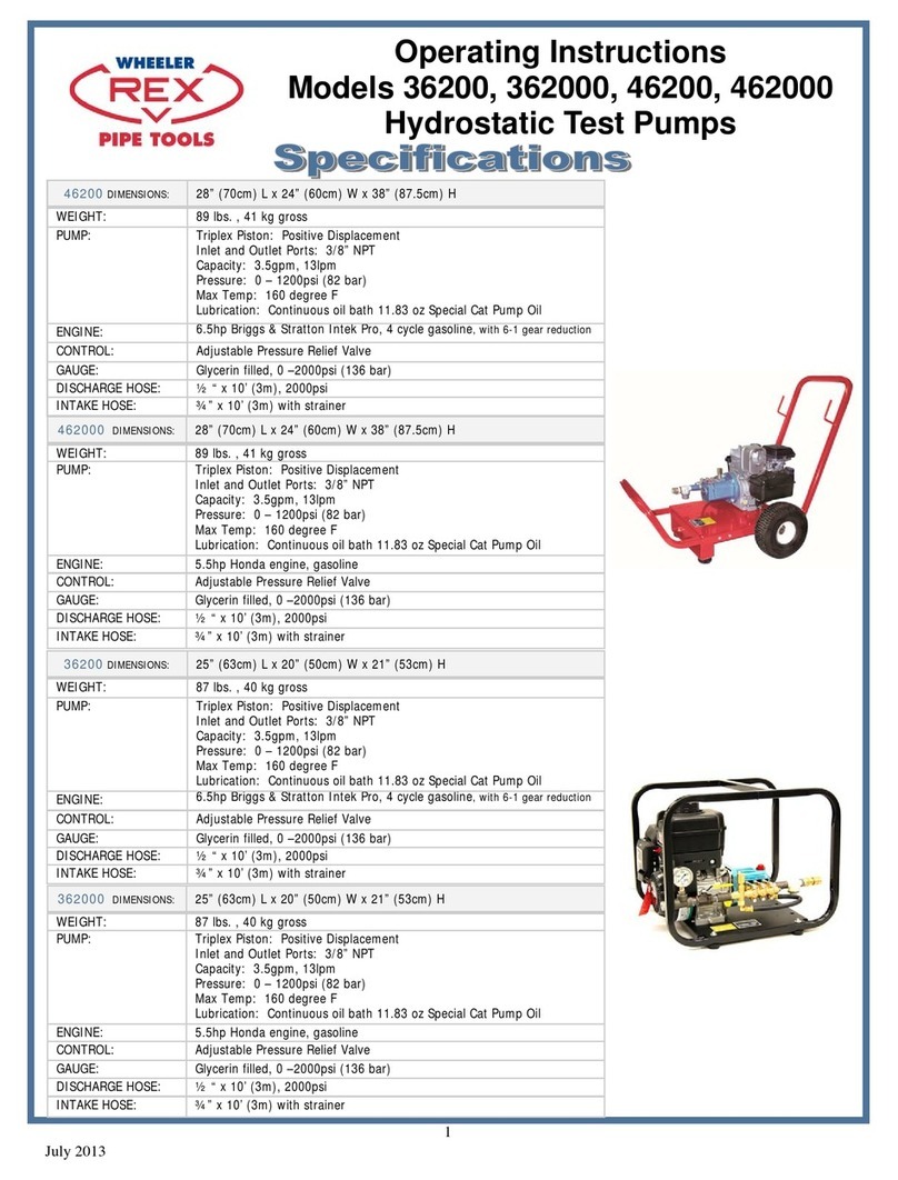
Mudsucker Trash Pump
 Sand Cast Aluminum Construction
 Thermoplastic Santoprene Diaphragm
 Gasoline powered
 3” NPT Suction / Discharge Ports
 Maximum Temperature 180 F
 .075” Keyed Shaft
 Self priming to 25 Ft. Lift
 Diaphragm pump
 Tank Size .052 gal / 2.0 lt
 Maximum Solids Handling Capacity: 1-5/8” diameter
 Complete with Oil Alert
Phone: 800-321-7950 or 440-998-2788
Fax: 440-992-2925
Email: [email protected]
3744 Jefferson Road
Ashtabula, OH 44004
www.wheelerrex.com
Wheeler-Rex
Model 56310
3” Capacity
Mudsucker Trash Pump
Unpacking
After unpacking the unit, inspect carefully for any
damage that may have occurred during transit. Check
for loose, missing or damaged parts.
Specific Safety Information for Gasoline
Engine Driven Pumps
1. Carefully read the instruction manuals supplied by
the engine manufacturer before attempting to assem-
ble/disassemble or operate the engine or any other
part. The “Warning” and “Caution” statements in this
manual signal potential hazardous conditions to the
operator or equipment. Know when these conditions
can exist. Take necessary steps to protect personnel
as well as equipment.
WARNING
Gasoline is a highly combustible fuel. Use it with care!
The improper use, handling and/or storage of gaso-
line can be dangerous. Help prevent accidents by
following these safety rules:
a. Use gasoline only as fuel, never as a cleaning fluid.
b, Always use an approved container to hold or store
gasoline. Never store gasoline in familiar containers
such as milk gallons or soda pop bottles.
c. Never store gasoline near a heater or an open
flame.
d. When storing or using gasoline, make sure
container is out of the reach of children.
e. Never add gasoline to a running or hot engine.
Spilled gasoline on a hot engine may cause a fire or
an explosion. Fill gasoline tank outdoors and wipe up
any spills.
f. Have a fire extinguisher nearby. Be sure extinguish-
er is in operating condition - check the pressure
gauge or indicator. Be familiar with its proper use.
Consult the local fire department for the correct type
of extinguisher for your application Extinguishers
rated ABC by the National Fire Protection Association
are appropriated for all applications.
g. On permanent installations, be sure all fuel
supplies have a positive shut-off valve. Fuel lines
must be of steel piping, adequately secured and free
from leaks. Do not use copper piping or flexible lines
as copper becomes hardened and brittle and will
break. Use black pipe on natural gas or gaseous
fuels, but not on gasoline or diesel fuels. Piping the
engine should be a suitable flexible line that is
compatible with the fluid.
Positively No Smoking!
2. Check engine oil, fuel levels and gear box oil levels
before initial startup each day. Stay away from mov-
ing parts due to the danger of becoming caught in
moving parts. Avoid loose jackets, shirts, sleeves and
ties. Make sure all nuts and bolts are secure. Keep
power shields and guards in place. If adjustment
MUST be made while the unit is running, use extreme
caution around hot manifolds, moving parts etc.
3. Do not work with this equipment when mentally or
physically fatigued.
4. Be careful not to touch the exterior of the engine,
especially the muffler and the area around it. It is hot
enough to be painful or cause injury.
5. To prevent accidental starting, always remove the
spark plug or disconnect and ground the spark plug
wire before working on the engine or the equipement
driven by the engine.
6. DO NOT RUN THE ENGINE IN AN ENCLOSED
AREA!!
Exhaust gases contain carbon monoxide, which is an
odorless and deadly gas that will cause death if
breathed too long. If equipment is located in an
enclosed area with an exhaust line to the outside,
regularly check the exhaust system for leaks. Be sure
the area is well ventilated.
7. If the gas engine is equipped with a spark arrester
screen in the muffler, it should be inspected for wear
periodically and replaced when necessary.
Specific Safety Information for Electric Motor
Driven Pump
1. This unit is not waterproof and is not intended to be
used in potentially wet locations. The motor is de-
signed to be used in a clean, dry location with access
to an adequate supply of cooling air. Ambient temper-
ature around the motor should not exceed 104° F
(40° C). For outdoor installations, motor must be pro-
tected by a cover that does not block air flow to and
around the motor. This unit is not weatherproof nor is
it able to be submersed in water.
2. When wiring an electrically driven pump, follow all
electrical and safety codes, as well as the most re-
cent United States National Electrical Code (NEC)
and the Occupational Safety and Health Act (OSHA).
WARNING
Risk of electrical shock! Never connect the green
(or green and yellow) wire to a live terminal
3. To reduce the risk of electric shock, the motor must
be securely and adequately grounded! This can be
accomplished by either (1) inserting plug (portable)
directly into a properly installed and grounded
Mudsucker Trash Pump
3-prong grounding-type receptacle (as shown in Fig-
ure 2); 2 permanently wiring the unit with a grounded
metal raceway system. (3) using a separate ground
wire connected to the bare metal of the motor frame,
or (4) other suitable means. The green (or green and
yellow) conductor in the cord is the grounding wire.
The motor must be securely and adequately ground-
ed for your protection against shock hazard. Where a
2-prong wall receptacle is encountered, it must be
replaced with a properly grounded 3-prong receptacle
installed in accordance with the National Electrcial
Code and local codes and ordinances. To ensure a
proper ground, the grounding means best be tested
by a qualified electrician. Use only 3-wire extension
cords that have 3-prong, grounding-type plugs and 3-
pole receptacles that accept the equipment plug.
Grounding Blade—Figure 2 Grounding Methods
4. All wiring should be performed by a qualified
electrician.
WARNING
An incorrect connection may cause an electric
short, produce an electrical shock or burn out the
pump motor, resulting in property damage and/or
personal injury.
5. Protect electrical cord from sharp objects, hot sur-
faces, oil and chemicals. Avoid kinking the cord. Re-
place or repair damaged or worn cords immediately.
6. Provide safety shields on all moving and electrical
parts to prevent personal injury.
7. Keep fingers and foreign objects away from ventila-
tion and other openings. Do not insert any objects
into the motor.
8. Use wire of adequate size to minimize voltage drop
at the motor.
9. Disconnect power before servicing a motor or its
load. If the power disconnect is out of sight, lock it in
the open position and tag it to prevent unexpected
application of power.
10. Do not touch an operating motor. Modern motors
are designed to operate at high temperatures.
General Safety Information
1. Know the pump application, limitations and poten-
tial hazards.
WARNING
Do not use to pump flammable or explosive fluids
such as gasoline, fuel oil or kerosene, etc. Do not
use in flammable and/or explosive atmospheres.
Pump should only be used with liquids compati-
ble with pump component materials. Failure to
follow this warning can result in personal injury
and/or property damage.
2. Make certain that the power source conforms to
the requirements of your equipment.
3. Provide adequate protection and guarding around
moving parts.
4. Disconnect power before servicing.
5. Release all pressure within the system before ser-
vicing any component.
6. Drain all liquids from the system before servicing.
7. Secure the discharge line before starting the pump.
An unsecured discharge line will whip, possibly daus-
ing personal injury and/or property damage.
8. Check hoses for weak or worn condition before
each use making certain that all connections are se-
cure.
9. Periodically inspect pump and system components.
Perform routine maintenance as required (see
Maintenance Section)
10. Provide a means of pressure relief for pumps
whose discharge line can be shut off or obstructed.
11. Personal Safety:
a. Wear safety glasses at all times when working
with pumps.
b. Wear a face shield and proper apparel when
pumping hazardous chemicals.
c. Keep work area clean, uncluttered and properly
lighted - replace all unused tools and equipment.
d. Keep visitors at a safe distance from the work
area.
e. Make workshop childproof - with padlocks, mas
ter switches and by removing starter keys.
12. For air drive units follow Safety Information
instruction sheet supplied with air motor.
Mudsucker Trash Pump
Assembly
1. Handle on 2” Pump
a. Remove two hex cap screws (Ref No A6) and
washers (Ref No A7) from gearbox (Ref No A1).
b. Place handle (ref No A35) on gearbox flange and
align holes.
c. Reinstall two hex cap screws and washer assem
blies, then tighten.
Handle on 3” Pump
d. Remove two hex nuts (Ref A14) from pump well
(Ref No A3).
e. Place handle (Ref No A35) under pump well.
f. Reinstall two hex nut and washer assemblies then
tighten.
2. Rotating suction / discharge ports (optional)
Refer to Figure A.W.P.
In some applications, it may be preferable to have
suction / discharge ports rotated 90° to be in line with
driver. If so, proceed as below:
a. Remove four hex cap screws (Ref No A9), hex
cap screws (Ref A13 & A14) from pump assem-
bly to separate pump well (Ref No A3) from pump
base (Ref No A8)
b. Rotate pump well 90 degrees clockwise so that
driver is positioned over top of discharge plate
(Ref No W7).
c. Be sure that pump well base and diaphragm (Ref
No P17) are aligned properly with one another.
Then reinstall four hex cap screws, hex nuts and
washer assemblies and tighten.
Gear Box Oil (Refer to Figure A, G)
3.Place pump on a level surface. Fill pump gear box
(ref No A1) with gear box oil before the pump is oper-
ated. Gear oil must meet requirements of API GL-5
and military specification MIL-L-2105B. Remove gear
box housing fill plug (Ref No G8). Remove level plug
(Ref No G5). Pour gear oil into gear box slowly until
oil comes out of level plug.
Warranty on this unit is void unless the gear box
is lubricated with appropriate gear oil listed
above. DO NOT OVERFILL!!!
Installation
NOTE: In any installation where property damage
can occur by pumps not operating due to power out-
ages, discharge line freezing or any other reason, a
backup system (s) and/or warning system (s) should
be used.
1. Place the pump on a level, solid foundation, locat-
ing it as close to the liquid as possible making the
suction line as short and direct as possible.
2. Install pipe nipples (Ref No A36) so the smoother
side of pipe end faces the suction and discharge
hose.
CAUTION
Maximum discharge head is 25 feet or 10.9psi. Oper-
ation over this head or pressure will cause pump to
stall and/or gearbox damage. Use only rigid hoses.
3. Attach suction piping to the suction inlet (ref No
W2) and discharge piping to the discharge outlet (Ref
No W7). The suction line should be positioned such
that there is a continual upward slope from the fluid
source to the pump. Avoid using loops or sections of
pipe or fittings, which might permit air to become
trapped.
NOTE: If hose is used, be sure to use reinforced
hose on both the suction and discharge. DO NOT
USE canvas or similar collapsible materials. NEV-
ER USE PIPE REDUCER; PIPE SIZE MUST BE
EQUAL TO OR LARGER THAN THE PUMP PORT
SIZE. Suction line must be airtight sot that air
cannot leak in and destroy priming vacuum. On a per-
manent installation where piping is used, always con-
nect a piece of flexible hose between pump and pip-
ing so pump is free to move slightly.
4. It is advisable to use a strainer. (Ref No W16) on
the inlet end of the suction hose or pipe. A properly
sized strainer is supplied with this unit and should be
used at all times to prevent damage. Keep the strain-
er clean. If possible, suspend it to keep it from being
clogged with muck., roots, debris or leaves. It is best
to keep hose free of kinks as they will restrict flow and
add excess loading to pump and gearing.
5. Gasoline Engine Units: Follow all instructions
in the engine manual before starting the engine. Fill
engine with oil, gasoline, etc.
Air Motor Units: Follow all instructions in the
air motor manual before starting unit.
Electric Motor Units: It is strongly recommend-
ed that this unit is plugged into a G.F.I. (Ground Fault
Interrupter) circuit. Consult your local electrician for
installation and availability.
6. Input RPM (to pump) - Input RPT must be between
1750 and 2750 RPM. Final pump speed will be 40
strokes/minute with a 1750RPM input and 60
strokes/minute RPM Input.
Mudsucker Trash Pump
Do not exceed 60 strokes per minute with the dia-
phragm pump.
Operation
Operate the diaphragm pump in an upright position
only.
1. This diaphragm pump is capable of priming “dry”
up to fifteen feet; it will prime much faster when it
is filled with clean water through priming cap (Ref
No W6). Primed, it can lift to 25 feet.
2. Activate unit following engine or air motor manual
turning unit on if electrical
CAUTION
Do not control discharge capacity with a valve or sim-
ilar device.
Clearing Jam Up
If large solids or an accumulation of sand or other
sediment becomes lodged in the pump well (Ref No
A3) preventing the plunger arm (Ref No A2) from
making a full stroke, the pump will either stall or the
crank (Ref No P5) will slip on the output shaft (Ref
No G8). The pump is designed to react this way to
prevent severe internal damage. If such a jam-up
does occur, the pump should be thoroughly cleaned
as described in “If Pump Stalls” within this section.
Refer to parts list and illustration for parts identifica-
tion.
CAUTION
If pump has stopped or stalled for any unknown rea-
son, clean out pump cavity thoroughly. Failure to
comply with the “caution” could result in damage to
crank (Ref No P5/P9), plunger arm (Ref No P1) or
other parts of assembly.
1. If pump stalls:
a. Remove handle (Ref No A35).
b. Remove four bolts (Ref No A9 & A10)
c. Clean obstruction & all debris from pump well
(Ref No A3).
d. Reassemble pump in reverse order of disas
sembly and return to service.
2. If Plunger Arm (Ref No P1) seizes and gear box
output shaft (Ref No G8) turns in crank (ref No P5):
a. Remove sheet metal guard (ref No A4) by loos
ening hand knob screws (Ref No A5)
b. Disassemble pump and clean as described in
Steps a thru d listed for stalled engine jam up.
c. Torque the crank lock screw (Ref No A6) to 70
foot pounds with an appropriate torque
wrench. See Figure 3.
d. Reassemble the pump in reverse order of disas-
sembly and return to service.
WARNING
Pump jamming with an over-torqued lock screw may
cause internal damage. Under torqueing may allow
the output shaft to spin and wear parts necessitating
replacement.
Maintenance
WARNING
Make certain that unit is disconnected from power
source before attempting to service or remove any
component.
1. Check gear box oil level every 20 hours of opera-
tion or at least once a week. More often if any
leakage is detected around the gear box. Change
gearbox oil after the first 40 hours of operation.
Fill to the oil level plug. Change gearbox oil every
350 hours of operation.
2. The plunger bearing (Ref No P3) must be
greased (any automotive grease) after every 8
hours of use. This is done by rotating plunger
bearing to the 12 o’clock position. At this point,
grease fitting will be visible throught hole in guard
(Ref No A4) Bearing may be cleaned and kept
well lubricated by pumping grease slowing into
fitting until new grease oozes out between bear-
ing and journal.
3. During freezing weather, be sure to drain the
pump when it is not running. Remove discharge
hose and tip unit towards discharge side.
4. Keep pump clean. After use with liquids contain-
ing foreign materials, flush with clean water.
Replacement of Flapper Valve (Ref No W15)
1. Remove two bolts (ref NO W3) and remove suc-
tion priming chamber (Ref No W2). Replace flap-
per (ref No W15) on flapper pin to locate on prim-
ing chamber.
2. Remove two bolts (Ref No W8) and remove
Mudsucker Trash Pump
discharge plate (Ref No W7). Replace flapper valve
on flapper pin to locate valve on pump well (Ref No
W1)
Replacement of Diaphragm (Ref No P17)
1. Remove sheet metal guard (ref No A4) by loos-
ening hand knob screws (ref No A5)
2. Rotate pump until plunger arm (Ref No A2) is in
the down position.
3. Remove handle (Ref No A35)
4. Remove pump well (Ref No A3) by removing
screws (Ref No A9/A10)
5. Remove diaphragm by removing three nuts (Ref
No P12) from bolts (Ref No P11)
6. Replace diaphragm and reverse steps 1 thru 5
for reassembly.
7.
Gear Box Overhauling
A completely assembled gear box is available as a
replacement part (Ref No G28).
Disassembly
1. Remove diaphragm (Ref No P13) as described in
“Replacement of Diaphragm”.
2. Remove crank (Ref No P5) by removing machine
screw (Ref No P6). Use screwdriver in slot of
crank to release clamp on output shaft (Ref No
G8).
3. Drain oil from gear box by removing drain plug
(Ref No G4).
4. Remove driver (Ref Nos A28/A32) from adapater
(Ref No G26) by removing four bolts (Ref No
A27) plus 4 additional bolts (Ref No A29) from
engine mount bracket (Ref No A16) for gas driver
models. Slide driver back from adapter until driv-
er shaft disengages pinion (Ref No G27).
5. Remove adapter by removing four bolts. (Ref No
G27)
6. Remove gear box from pump base (Ref No A8)
by removing four bolts (Ref No A9 & A10).
7. Remove pinion bearing assembly (Ref Nos G15,
G24, G20, G16) by pulling straight out. Use a
slide hammer puller gripping in pinion groove.
8. Remove twelve bolts (Ref No G3) holding gear
box halves (Ref Nos G1 & G2)together.
9. Carefully separate gearbox halves.
10. Remove gasket (Ref No G22)
11. Remove output shaft/bearing assembly (Ref Nos
G8, G9, G12, G11, G12, G13) and idler pin-
ion/bearing assembly (Ref Nos G13, G14, G17,
G18, G19)
12. Remove output shaft oil seal (Ref No G23)
13. Remove bearings (Ref Nos G15 & G18) from
ends of input pinion shaft (Ref No G20)
14. Remove bearings (Ref Nos G13 & G14)from ends
of idler pinion shaft (Ref No G20).
15. Remove internal spur gear (Ref No G19) and key
(Ref No G18) from idler pinion shaft.
16. Remove retaining ring (Ref No G10) and bearings
(Ref Nos G12 & G13) from ends of output shaft
(Ref No G8).
17. Remove output gear (Ref No G11) and key (Ref
No G9) from output shaft.
Reassembly
1. Assemble input pinion/bearing assembly, idler
pinion bearing assembly and output shaft/bearing
assembly.
2. Install output shaft oil seal into gearbox output
half. Lubricate lip seal.
3. Slide output shaft throught lip seal. Start output
bearing in bore in gear box output half. Simulta-
neously press both assemblies into output half.
4. Install gasket on output half.
5. Position gear box input half, align shaft bearings
with bearing bores. Press gear box halves togeth-
er, align pins in output half with pin bore in input
half.
6. Secure halves together with twelve bolts.
7. Slide input pinion/bearing assembly into bore in
gear box input half. Rotate pinion during installa-
tion to make sure gear teeth align with internal
spur gear teeth.
8. Install O-Ring (Ref No G25) on outside of pinion
bearing.
9. Reassembly gear box to pump base with four
bolts.
10. Reassembly adapter to gear box with four bolts.
11. Align driver shaft key (Ref No A26) with keyway
in pinion. Slide driver into position, secure to
adapter with four bolts (Ref No A27).
a. (Gas Engine Only) Attache engine to engine
mount with four additional screw assemblies
(Ref No A29).
12. Reassemble crank to output shaft as described
under “Replacement of Diaphragm” section.
13. Replace diaphragm as described under
“Replacement of Diaphragm” section.
14. Fill gear box with oil as described under “
Assembly” dection.
15. Pump should be check daily, weekly, monthly for
proper operation.
Mudsucker Trash Pump
NOTE:
Only qualified service personnel should attempt to
repair this unit. Improper repair and/or assembly can
cause pump damage, driver damage and/or an elec-
trical shock hazard depending on the model.
Mudsucker Trash Pump
Wheeler - Rex •Ashtabula, Ohio
Tel: 800-321-7950 440-998-2788
Fax: 440-992-2925
[email protected]
www.wheelerrex.com

Other Wheeler-Rex Water Pump manuals

Wheeler-Rex 36200 User manual

Wheeler-Rex

Wheeler-Rex 36200 User manual

Wheeler-Rex 465210 User manual

Wheeler-Rex

Wheeler-Rex 465210 User manual

Wheeler-Rex 35100 User manual

Wheeler-Rex

Wheeler-Rex 35100 User manual

Wheeler-Rex 29201 User manual

Wheeler-Rex

Wheeler-Rex 29201 User manual

Wheeler-Rex 39300 User manual

Wheeler-Rex

Wheeler-Rex 39300 User manual

Wheeler-Rex 29900 User manual

Wheeler-Rex

Wheeler-Rex 29900 User manual

Wheeler-Rex 47100 User manual

Wheeler-Rex

Wheeler-Rex 47100 User manual

Wheeler-Rex 36454 User manual

Wheeler-Rex

Wheeler-Rex 36454 User manual

Wheeler-Rex 46701 User manual

Wheeler-Rex

Wheeler-Rex 46701 User manual

Popular Water Pump manuals by other brands

Siccom FLOWITA EVO quick start guide

Siccom

Siccom FLOWITA EVO quick start guide

Intex Quick-Fill AP643 owner's manual

Intex

Intex Quick-Fill AP643 owner's manual

Schmalz EVE-TR 250 AC3-F operating instructions

Schmalz

Schmalz EVE-TR 250 AC3-F operating instructions

Briggs & Stratton Pro series Operator's manual

Briggs & Stratton

Briggs & Stratton Pro series Operator's manual

Annovi Reverberi AR 80 bp instruction manual

Annovi Reverberi

Annovi Reverberi AR 80 bp instruction manual

IWAKI PUMPS MDM Series instruction manual

IWAKI PUMPS

IWAKI PUMPS MDM Series instruction manual

Nippon Oil Pump Cyclone Filter Pump User instruction manual

Nippon Oil Pump

Nippon Oil Pump Cyclone Filter Pump User instruction manual

Pentair HYDROMATIC SH Installation and service manual

Pentair

Pentair HYDROMATIC SH Installation and service manual

Sagola DM1/300 Instruction manual / spare parts list

Sagola

Sagola DM1/300 Instruction manual / spare parts list

Stermay 782A Plus Operation instructions

Stermay

Stermay 782A Plus Operation instructions

Intex Quick-Fill 58609 operating instructions

Intex

Intex Quick-Fill 58609 operating instructions

GORMAN-RUPP PUMPS ULTRA V V3C60SC-B Series Installation, operation, and maintenance manual with parts list

GORMAN-RUPP PUMPS

GORMAN-RUPP PUMPS ULTRA V V3C60SC-B Series Installation, operation, and maintenance manual with parts list

Ingersoll-Rand ARO 666300 C Series Operator's manual

Ingersoll-Rand

Ingersoll-Rand ARO 666300 C Series Operator's manual

Aqua Systems Electric KFC Series instruction manual

Aqua Systems

Aqua Systems Electric KFC Series instruction manual

Hydra-Cell T100 Series Installation operation & maintenance

Hydra-Cell

Hydra-Cell T100 Series Installation operation & maintenance

Ulvac ULK-04A instruction manual

Ulvac

Ulvac ULK-04A instruction manual

Shop Tuff STF-PHOP owner's manual

Shop Tuff

Shop Tuff STF-PHOP owner's manual

GORMAN-RUPP PUMPS GMS Series Installation, operation and maintenance manual

GORMAN-RUPP PUMPS

GORMAN-RUPP PUMPS GMS Series Installation, operation and maintenance manual

manuals.online logo
manuals.online logoBrands
  • About & Mission
  • Contact us
  • Privacy Policy
  • Terms and Conditions

Copyright 2025 Manuals.Online. All Rights Reserved.