Page 2
FLASHER
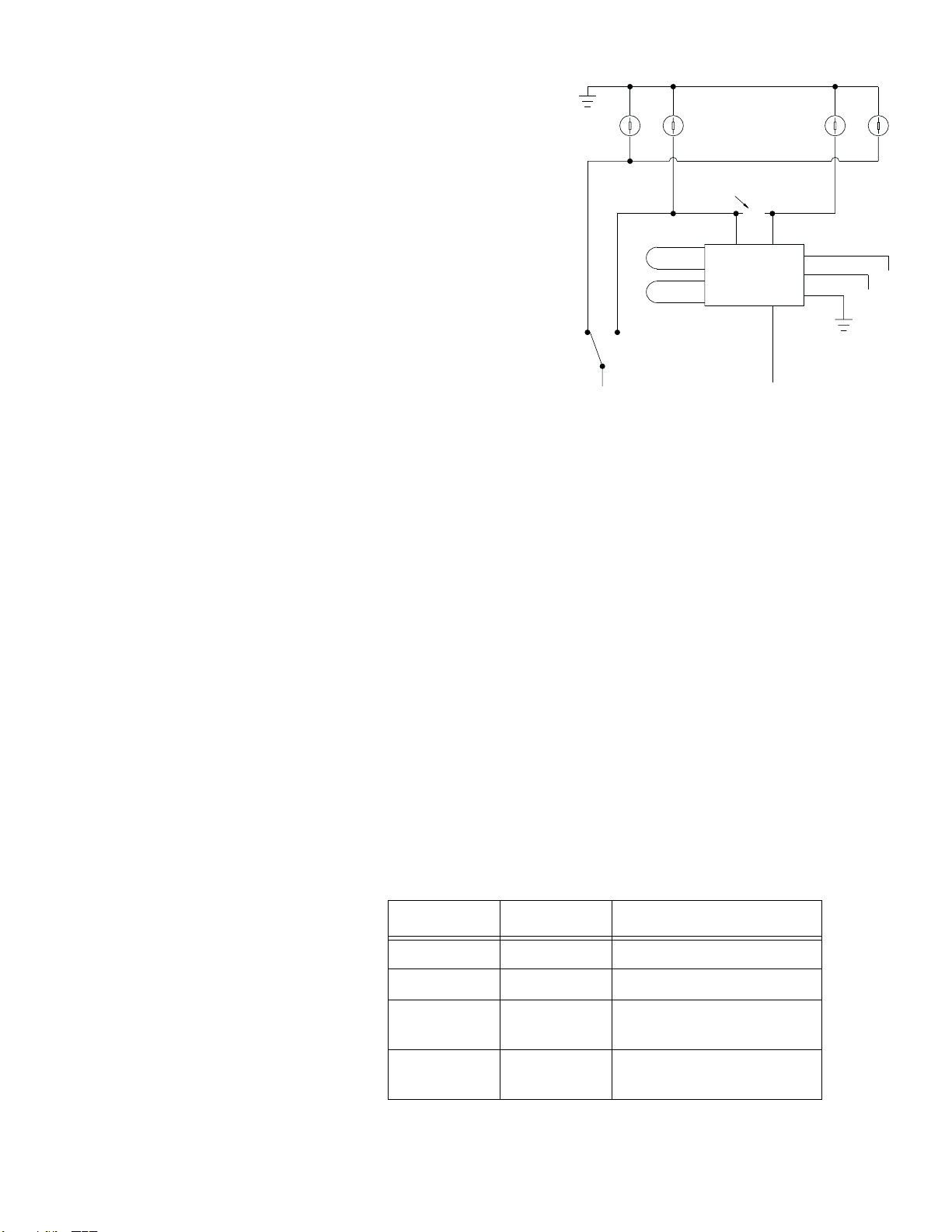
CONTROL +BAT
GROUND
RED
POWER +BAT
BLACK
ORANGE
YELLOW
BLUE
WHITE/VIOLET
PATTERN 2
PATTERN 1
WHITE/RED
CUT OEM WIRE AND SPLICE
DRIVER
HILO
X
WIRING DIAGRAM
PASS
HI LO
HIGH BEAM SWITCH (+)
LOW BEAM SWITCH (+)
HEADLIGHT
GROUND
BLUE AND YELLOW AS SHOWN
PARKING LIGHTS +BAT
BROWN
Installation
There are two different switching methods used to activate the headlight/parking lights in a motor vehicle; Positive-Side
Switching and Ground-Side Switching. For example, the headlights may use Positive-Side switching, while the parking lights
may use Ground-Side switching. This product is designed for use only with POSITIVE-Side headlight switching! Before
installing this product, it will be necessary to contact the vehicle manufacturer to confirm that the vehicle in question uses
Positive-Side switching.
1. Mount the UHFPOS in the engine compartment near the battery and headlights. DO NOT mount the unit directly on the
engine or close to the exhaust system.
2. Connect the UHFPOS wires to the vehicle as outlined here.
BLACK - Connect to the vehicle’s chassis ground.
BROWN - Connect to the parking light to disable flasher when headlights are on.
BLUE - Connect to the end of the cut wire from the driver-side high beam headlight (see wiring diagram). This BLUE
wire may be extended using 14 AWG wire.
YELLOW - Connect to the end of the cut wire from the passenger-side high beam headlight (see wiring diagram). This
YELLOW wire may be extended using 14 AWG wire.
ORANGE - Connect to a +12VDC power switch (200 mA MIN./customer supplied).
RED - Connect, fused at 15 Amps (customer supplied) to the POS (+) battery terminal.
3. Test the flasher for proper operation
Flash Pattern Selection
There are 4 available flashrates for the
UHFPOS.These rates are determined
by two jumper wires;WHITE/RED and
WHITE/VIOLET. The following table defines
the available flashrates.
IMPORTANT NOTES!
• The use of a flashing headlight system may be regulated by state,
county, or municipal authorities. It is the responsibility of the end
user to comply with these regulations.
• The installation of a headlight flasher system requires a
modification to the standard headlight wiring harness. This
modification may effect the warranty of your vehicle. It is the
responsibility of the end user to verify the warranty conditions with
the vehicle manufacturer. Also, the use of a headlight flasher may
shorten the high beam bulb life.
• Before attempting the installation of the UHFPOSEC headlight
flasher, thoroughly read and understand instructions and steps
shown below!
• Disconnect the battery from the electrical system before attempting
any part of this installation!
• All customer supplied wires that connect to the positive (+) terminal
of the battery, must be sized to supply at least 125% of the
maximum operating current, and be fused “at the battery” to carry
that load.
SF = Single Flash per min.
DF = Double Flash per min.
WHT/RED WHT/VIO Flashrate
Intact Intact Moduflash
CUT Intact 280 SF Alternating
Intact CUT 140 DF Alternating
140 SF Simultaneous
CUT CUT 140 DF Alternating
280 SF Alternating


