Page 2
Mounting your Lightbar:
Refer to the Lightbar mounting guide included with your lightbar.
IMPORTANT! The lightbar should be a minimum of 16" from any
radio antennas!
Routing your Lightbar Cable(s)
1. To protect the headliner from damage caused by drilling the cable access hole
through the vehicle roof, allow a 5” to 7” distance between roof and headliner
by lowering the headliner before drilling.
WARNING! There may be a roof support member that spans the distance
between the driver’s and passenger’s side. DO NOT DRILL THROUGH
THIS MEMBER! Adjust the location until the hole can be drilled without
contacting this support member.
2. Using a 1” hole saw, drill the cable access hole. Use a round file to smooth and
de-burr the edges, then insert a 1” grommet.
3. Insert the cable(s) through the cable access hole into the vehicle. Use RTV
silicone to weatherproof the access hole after the cable(s) are pulled
completely into the vehicle.
4. Route the cable(s) following manufacturers recommendations.
WARNING: Many vehicles are now equipped with side curtain and B-pillar
air bags. Alternate routing may be required.
Connecting the Cables:
WARNING! All Customer supplied wires that connect to the positive
terminal of the battery must be sized to supply at least 125% of the
maximum operating current and FUSED at the battery to carry that load.
DO NOT USE CIRCUIT BREAKERS WITH THIS PRODUCT!
Power Cable:
1. Open the wiring shield lid and route the power cable into the wiring shield and
towards the firewall. Make sure you do not to pinch or crush any wires
when running them through the wire shield.
2. Follow the factory wiring harness through the firewall. It may be necessary to
drill a hole in the firewall. If so, be absolutely sure that there are no
components that could be damaged by drilling. After the hole has been
drilled, insert a grommet to protect the cable.
3. Route the cable along the factory wiring harness to the battery.
4. Install a 30 amp fuse block (customer supplied) on the end of the RED wire in
the power cable. Remove the fuse from the fuse block before connecting any
wires to the battery.
5. Connect the fuse block to the POSITIVE (+) terminal on the battery. There
can not be more than two feet of wire between the fuse block and the battery.
The wire between the fuse block and the battery is “unprotected”, do not
allow this wire to touch any other wires.
6. Connect the BLACK wire to the factory chassis ground.
Operation:
Cruise Lights & AUX (WHITE/ORANGE):
The WHITE/ORANGE wire operates in one of 3 different modes. Selecting a mode is
controlled by the Scan-Lock™ wire. Using Scan-Lock, choose between the 3
available modes as though you were changing flash patterns.
MODE 1 (Default) - Cruise Lights activated in Low Power. AUX port activated.
MODE 2 - Cruise Lights are activated in High Power and the AUX port is activated.
MODE 3 - Cruise Lights are not activated and the AUX port is activated.
Hi/Low Power (VIOLET):
The switch used depends on how the operator wishes the Hi/Low feature to function:
Latching Mode: By applying +12 VDC voltage to the VIOLET wire for less than 1
second, the lightbar is “latched” into low power operation. The unit must be turned off
and then back on to restore normal, high power operation (Momentary Switch).
Level Mode: Applying +12 VDC voltage to the VIOLET wire for more than 1 second
holds the lightbar in low power mode until voltage is removed (Toggle Switch).
IMPORTANT NOTE: The corner modules in your lightbar do not switch to low
power when this option is applied. They will always remain in high power.
Scan-Lock™ (WHITE/VIOLET):
TO CYCLE FORWARD THROUGH AVAILABLE PATTERNS: Activate ONLY the
control wire of the function you wish to effect, then apply +12 volts to the WHT/VIO
wire for less than 1 second and release. This will change the pattern. For example, to
change the Front, Outboard LED pattern, apply +12VDC to the GREEN/WHITE wire
and then momentarily apply +12VDC to the WHT/VIO wire. Repeat until the desired
pattern is displayed. Let this pattern run for at least 5 seconds to configure it as the
pattern the Front Outboard LEDs will display when activated. Repeat to advance to
the next pattern. Only ONE function may be active while changing patterns.
TO CHOOSE A PATTERN: Allowing the desired pattern to run for more than 5
seconds will make it the default pattern.
TO RESET TO THE FACTORY DEFAULT PATTERN: Turn off all lightbar functions.
Apply +12 volts to the WHT/VIO wire and turn the appropriate function back on. This
function is now restored to its factory default pattern.
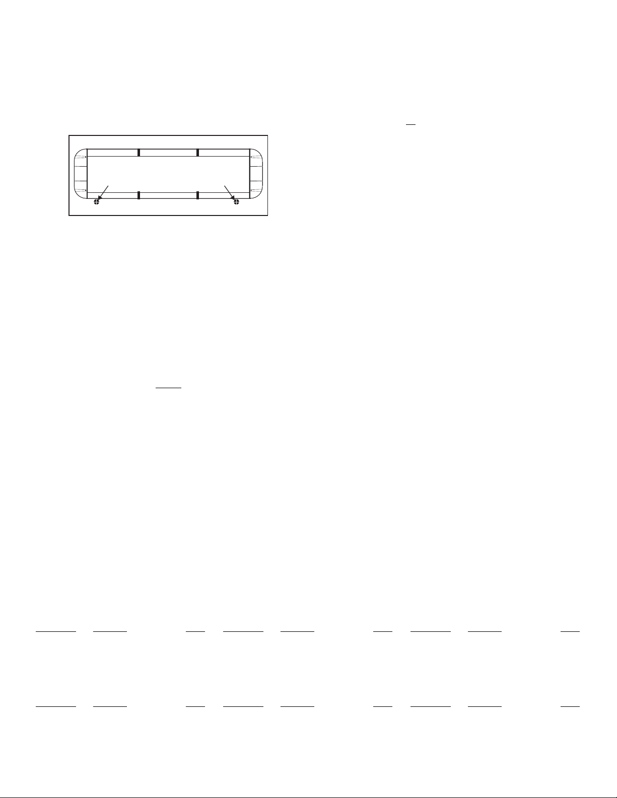
DRILLING THE CABLE ACCESS HOLE
Drill cable access hole in appropriate area
for your lightbar (see note)
FRONT OF LIGHTBAR
For
cables exiting
the Driver-side
of the extrusion
lightbars
with
For
cables exiting
the Passenger-side
of the extrusion
lightbars
with
1 - GREEN . . . . Driver-side Corner LED’s. . . . . . . . . 3A
2 - BLUE. . . . . . Passenger-side Corner LED’s. . . . .3A
3 - GRN/WHT . . Driver-side Outboard LED’s. . . . . . .3A
4 - BLU/WHT . . Passenger-side Outboard LED’s. . .3A
5 - GRN/BLK . . Driver-side Inboard LED’s . . . . . . . . 3A
6 - BLU/BLK. . . Passenger-side Inboard LED’s . . . .3A
7 - WHT/GRN . . NOT USED
8 - WHT/BLU . . NOT USED
9 - YELLOW. . . NOT USED
10 -WHITE . . . . NOT USED
11 -WHT/BLK . . NOT USED
12 -WHT/ORG. . Cruise Lights & AUX . . . . . . . . . . . . 5A
13 -WHT/YEL . . NOT USED
14 -WHT/BRN. . NOT USED
15 -VIOLET. . . . Hi/Low Power . . . . . . . . . . . . . . . 0.5A
16 -WHT-VIO . . Scan-Lock™ . . . . . . . . . . . . . . . . 0.5A
17 -WHT/RED . . NOT USED
18 -NONE . . . . . RFI shield drain / to ground
Wire Color Function Fuse Wire Color Function Fuse Wire Color Function Fuse
Control Cable:
Extend the control cable to your switch panel and make your connections using the information provided. The control cable connects to your control head or switch box and is
fused there. Applying +12VDC to a control wire activates its function. Fuse as noted below. IMPORTANT! Insulate any unused wires.
SLTXDOT3 & SLTXDOT4
1 - GREEN . . . . Front Corner LED’s . . . . . . . . . . . . . 3A
2 - BLUE. . . . . . Rear Corner LED’s . . . . . . . . . . . . .3A
3 - GRN/WHT . . Front Outboard LED’s . . . . . . . . . . .3A
4 - BLU/WHT . . Rear Outboard LED’s . . . . . . . . . . . 3A
5 - GRN/BLK . . Front Inboard LED’s . . . . . . . . . . . . 3A
6 - BLU/BLK. . . Rear Inboard LED’s. . . . . . . . . . . . .3A
7 - WHT/GRN . . NOT USED
8 - WHT/BLU . . NOT USED
9 - YELLOW. . . NOT USED
10 -WHITE . . . . NOT USED
11 -WHT/BLK . . NOT USED
12 -WHT/ORG. . Cruise Lights & AUX . . . . . . . . . . . . 5A
13 -WHT/YEL . . NOT USED
14 -WHT/BRN. . NOT USED
15 -VIOLET. . . . Hi/Low Power . . . . . . . . . . . . . . . 0.5A
16 -WHT-VIO . . Scan-Lock™ . . . . . . . . . . . . . . . . 0.5A
17 -WHT/RED . . NOT USED
18 -NONE . . . . . RFI shield drain / to ground
Wire Color Function Fuse Wire Color Function Fuse Wire Color Function Fuse
SLTXDOT1 & SLTXDOT2
Front Corner, Rear Corner,
Outboard, Inboard and Center:
1. SignalAlert™ 75
2. CometFlash® 75
3. DoubleFlash 150
4. DoubleFlash 150
5. SingleFlash 375
6. SingleFlash 150
7. SingleFlash 75
8. ActionFlash 150
9. ModuFlash™
10. ActionScan™
Front Outboard, Inboard and Center:
1. SingleFlash 75
2. CometFlash® 75
3. DoubleFlash 150
4. DoubleFlash 75
5. SingleFlash 375
6. SingleFlash 150
7. SingleFlash 75
8. ActionFlash™ 150
9. ModuFlash™
10. Steady / SF75
11. Steady / Steady
12. ActionScan™
Take-Down / Alley
1. TD & Alley - SingleFlash 240 ALT
2. TD & Alley - DoubleFlash 120 ALT
3. TD Only - SingleFlash 240 SIM
4. TD Onlt - DoubleFlash 240 SIM
TrafficAdvisor™ Sequence
1. Sequence to Solid
2. Sequence On - Sequence Off
3. One Lamp Triple
4. Two Lamp Triple
Available Flash Patterns:


