manuals.online logo
Brands
  1. Home
  2. •
  3. Brands
  4. •
  5. Whirlpool
  6. •
  7. Range
  8. •
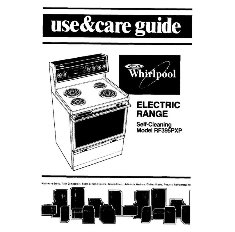
  9. Whirlpool RF375PXEN0 User manual

Whirlpool RF375PXEN0 User manual

InjuryHazard
All ranges cantip.
Install anti-tip device
packedwith range.See
InstallationInstructions.
Failureto do so could
resultin injury.
Quick Reference
Table of Contents:
Page_
[]
[]
[]
I B_k,over]
[a_k ©o,er]
Before you start
Product dimensions
Cabinet dimensions/requirements
Electrical requirements
Installation steps
If range does not operate
If you need assistance/service
Moving the range
If you need assistance:
Checkyour Use and Care Guide for a toll-free number to call or call the
dealerfrom whom you purchasedthis appliance. The dealer islisted in
the Yellow Pages of your phone directory under "Appliances--
Household -- Major-- Service and Repair."
Call when you:
[] Have questions about range installationor operation.
[] Need to obtain the name and number of an authorized
servicecompany,
When you call, you will need:
[] The range model number. "-2,_--_i,_0
[] The range serial number,
Both numbers are listed on the model/serial rating plate located on the
oven frame behind the storage drawer )anel.
Important: Observe all governing codes
and ordinances.
Proper installation isyour responsibility. A qualified
technician must installthis range. Make sure you
haveeverything necessaryfor correct installation. It
isthe installer's responsibilityto comply with
installation clearancesspecified on the model/serial
rating plate.The model/serial rating plate is located
on the oven frame behindthe storagedrawer panel.
Checklocation where range will be installed. The
range should be locatedfor convenient use in
kitchen.
ALLOPENINGS IN THE WALL OR FLOORWHERE
RANGE ISTO BEINSTALLEDMUST BESEALED.
Cabinet opening dimensions that are shown must
be used.Given dimensions are minimum
clearances.
Grounded electrical outlet is required. See
"Electrical requirements," Page 2.
Electrical Shock Hazard
It is the customer's responsibility to contact
a qualified electrical installer and to make sure
that the electrical installation is adequate and in
conformance with National Electrical Code,
ANSI/NFPA 70 -- latest edition*, and all local
codes and ordinances.
Take specialcare when cutting holes in wall or
floor. Electrical wires may be behind the wall or
floor covering and could cause an electrical
shock if you touch them.
Locate any electrical circuits that could be
affected by the installationof this product and
disconnect power circuit.
Failureto follow these instructions could result
in death or serious injury.
Injury Hazard
To eliminate the risk of burns or fire avoid
installing cabinet storage above the cooking
surface. If cabinets are already installed, reduce
the hazard of reachingover a heated cooking
surface by installing a range hood. The range
hood shouldextend a minimum of 5 inchesout
from the bottom front of the cabinets.
Reachingover a heated cooking surface could
result in a serious burn or other injury.
Mobile home installation
The installation ofthis range mustconform with the
Manufactured Home Constructionand Safety
Standard, Title 24 CFR,Part 3280 [formerly the
Federal Standard for Mobile Home Construction
and Safety, Title 24, HUD (Part 280)] or, when such
standard is not applicable,the Standard for
Manufactured Home Installations, ANSI
A225.1/NFPA 501A, or with localcodes.
When this range isinstalled in a mobile home, it
must be securedtothe floor during transit. Any
method of securing the range isadequate as long
as it conformsto the standards listedabove.
Four-wire power supply cord or cable must be used
in a mobile home installation. The appliance wiring
will need to be revised. See "Four-wire electrical
connection," Page 3.
Copiesofthe standardslisted may be obtainedfrom:
*NationalFireProtectionAssociation
BatterymarchPark
Quincy,Massachusetts02269
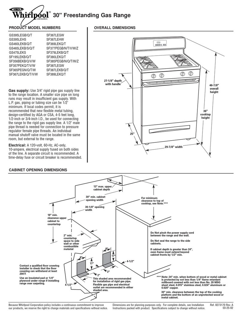
27-1/8" depth
with handle
24.13/16"
46-7/8"
overall
height
29.7t8"width
_i_'-__e 't-o"thatop
r-" jof ook op,
_li 30-1/S" ope_ng Note.**
width
18" min.
clearance upper
caEinet to _
countertop I
4" min. ,_ -",_r I
ceuntertop_ _._
Ispace to side f r _
.L wall or other
_.. combustible /_._
material
I
I
I
I
I..--
I
%. %. %.
Wall receptacle --
8" to 22" from either
cabinet, 5-1/2" max.
from floor. Position
reeeptade asshown,
5-1/2"
**Note: 24" rain. when bottom of wood or metal
cabinet isprotected by not less than 1/4" flame
retardant millboard covered with not lessthan
No. 28 MSG sheet steel, 0.015" stainless steel,
0,024" aluminum or 0.020" copper.
30" min. clearance between the top of the
cooking platform and the bottom of an
unprotected wood or metal cabinet.
Do Not pinch the power
supply cord between the
range and the wall.
Do Not seal the range to
the side cabinets.
Anti-tip bracket
The floor-mounted anti-tip bracket MUST be installed.
To install the anti.tip bracket shipped with the range, see
Page 2 and the anti-tip bracket template/instruction sheet.
flat-blade'
screwdriver
I\\\_ 3/a" drive 318"and 5/16"
_nut driver
measuring tape
or ruler
Page I
hand or
electric drill
safety
glasses
%wood floors:
1/8" drill bit
€oncrete/ceramic floors:
3/16" carbide-tipped masonry
drill bit {Hammer may be
needed for anchors.)
channel lock
2p,.:,i:
floor, mo unt_ _2 screwsN:: :hXo_ln/:;'")
anti-tip bracket literature pack
3 brass terminal block nuts
Brackets must be securely mounted to sub-floor. Thickness of
flooring may require Ion9er screws to anchor bracket to sub-
floor. Longer screws are available from your local hardware
store.
Electrical Shock Hazard
Electrical ground is requiredon this range.
Do Not ground to a gas pipe.
Do Not change the power supply cord plug. If it
does notfit the outlet, have a proper outlet
installed by a qualified electrician.
Do Not have a fuse in the neutral or grounding
circuit. Afuse in the neutral or groundingcircuit
could result in electrical shock.
Do Not usean extensioncordwiththis appliance.
Check with a qualified electrician ifyou are not
sure the range is properly grounded,
Failure tofollow these instructionscould resultin
death or serious injury.
If codes permit and a separate grounding wire is
used, it is recommended that a qualified electrician
determine that the grounding path is adequate.
Power supply cord is not supplied, but is available
through your local electrical supply house.
Range must be connected to the proper electrical
voltage and frequency asspecified on the model/serial
rating plate. (The model/serial rating plate is located on
the oven frame behind the storage drawer panel.)
[] CONNECTWITH COPPERWIRE ONLY.
[] A three-wire or four-wire, single-phase, 120/240-
volt, 60-Hz,AC-only, electrical supply (or three-wire or
four-wire 120/208-volt if specified on the model/serial
rating plate) is required on a separate, 40-ampere
circuit, fused on both sides of the line,
[] A time-delay fuse or circuit breaker is
recommended.
[] Local codes may permit the use of a U.L.-listed,
250-volt, 40-ampere range power supply cord (pigtail).
This cord contains three, No.-10 copper wires and
matches a three-wire receptacle of NEMA Type 10-50R,
shown in Figure 1.Connectors on the appliance end
must be provided at the point the power supply cord
enters the appliance.
[] The range can be connected directly to the fused
disconnect (or circuit breaker box) through flexible,
armored or non-metallic sheathed, copper cable (with
grounding wire). Allow two to three feet of slack in the
line so that it can be moved if servicing is ever
necessary.
A U.L.-listed conduit connector must be provided at
each end of the power supply cable (at the range and at
the junction box).
Wire sizes (COPPERWIRE ONLY) and connectionsmust
conform with the rating of the range (4g-amperes).
[] The wiring diagram is located on the back of the
range or on the inside of the storage drawer in a clear
plastic bag.
If connecting to a four-wire system:
This range is manufactured with the ground
connected to the cabinet. The ground must be
revised sothe green grounding wire ofthe four-
wire power supplycord is connectedto the
cabinet. See "Four-wire electricalconnection,"
section, Page3.
When a four-wire receptacle of NEMA Type 14-
50R isused (see Figure 2), a matching U.L.-listed,
four-wire, 250-volt, 40-ampere, range power
supply cord (pigtail) must be used.This cord
contains four copper conductors with ring
terminals at the appliance end, terminating in a
NEMA Type 14-50P plug on the supply end. The
fourth (grounding) conductor must be identified
by a greenor green/yellow cover and the neutral
conductor bya white cover. Cordshould beType
SRD or SRDT with a U.L.-listed strain relief and be
at leastfour feet long.
The MINIMUM conductor sizes for the copper
four-wire power cord are:
40-ampere circuit
2, No.-8 conductors
1, No,d0 white neutral
1, No.-8 green grounding
U
3-wire wall
receptacle (lObaR} 4-wire wall
receptacle {14-50R)
Rgure I Figure 2
Preparation
Injury Hazard
Becauseof the weight and size of this range,
two or more people are required to move it.
Do Not use handle for lifting.
Failure to follow these instructions could
result in injury.
Put on safety glasses and gloves.
• Remove oven racks and parts package
from inside oven. Remove shipping materials,
tape and protective film from range.
cardboard__ /._
shtppmgbase _V
•DO Not remove the cardboard shipping
base at this time.
front leveling leg
i
rear leveling leg
•Remove storage drawer. Use a 3/8'
drive ratchet to lower rear leveling legs one-
half turn. Use channel lock pliers to lower front
leveling legs one-half turn.
Anti-tip bracket installation
Electrical Shock
Take special care when drilling holes in
the floor or wall. Electrical wires may be
located beneath the floor or behind the
wall.
Locate the electrical circuits that could
beaffected by the installation ofthe
anti-tip bracket and turn off power to
these circuits.
Failureto follow these instructions could
result in death or serious injury,
Injury Hazard
To reduce the risk of tipping, the range
must besecured by a properly installed
floor.mounted anti-tip bracket, supplied
with the range.
Save these Installation Instructions. If
the range is movedto a new location,
the anti-tip bracket must be removed
and reinstalled in the new location.
Failureto follow these instructionscould
resultin injury.
Contacta qualified floor covering installer for the
best procedure for drilling mounting holes
through your type floor covering.
Use the anti-tip bracket
• template/instruction sheet to install the
anti-tip bracket.
Anti-tip bracket must be anchored
securelyto the sub-floor.
Dependingon the thickness
of your floodng, longer screws
may be necessaryto anchor the
bracketto the sub-floor.
Longerscrews are
available from your local
hardware store.
Check that range is on cardboard shipping base
to protect floor covering,
• Move range close to final operating
position.
Page2
Electricalconnection
Electrical Shock Hazard
Electrical ground is required on this range.
Do Not connectto the electrical supply until
the range is permanently grounded.
Disconnectthe power to the junction box
before makingthe electrical connection.
This range must beconnected to a grounded,
metallic, permanent wiring system or a
grounding connector should be connected to
the grounding terminal or wire lead on the
range.
Failure to follow these instructions could
resultin death or serious injury.
Pull coverdown
and remov_7
2mounting
tabs,
screws
Remove theterminal block cover screws
located onthe backof range. Pullcover
down and towards you to remove cover from
range.
Depending on your electrical supply,
•make the three-wire or four-wire
connection following the "Power supply cord
method" or "Direct wire method" instructions.
This range is manufactured with the neutral
terminal connected tothe cabinet. Use a three-
wire, U.L.-listed, 40-ampere power supply cord
(pigtail); or if local codes Do Not permit
grounding through the neutral, use a four-wire
power supply cord rated at 250 volts, 40-amperes
and investigatedfor use with ranges. (See "Four-
wire electrical connection.")
remove knockout//_ing for
for40-ampere \._._ _conduit
power cord and _=::::_r,.-_"_ _ connector
U,L listed strain _,, _.,_,....._..._
rehef
1,Disconnect the power supply.
2. Remove the knockout for the 4g-ampere
power supply cord.
3. Assemble a U.L-listed strain relief in the
opening.
4. Insert the power supply cord through the
strain relief, allowing enough slack to easily
attach the wiring to the terminal block.
5, Use only ring-type terminals to connect the
power supply. To secure the power supply
cord, use the 3/8' brass terminal nuts attached
to the inside of the terminal block cover, Be
sure nuts are installed tight.
6, Complete electrical connection according to
your type electrical supply ("Three-wire
electrical connection" or "Four-wire electrical
connection.')
Three-wire electrical connection:
silver-colored
terminal
block screw..,,
link
(center wire)
U,L-listed strain relief
and 4a-ampere range
power supply cord
Figure3
Usethis method ONLY if local codesPERMIT
connectingcabinet-grounding conductorto neutral
wire of power supply cord.
7. Use the brass terminal nuts attached to the
inside of the terminal block cover to connect the
neutral wire (center wire) to the silver-colored
terminal screw on the terminal block.
See Figure 3,
8. Connect the other two wires to outer terminal
screws on the terminal block. See Figure 3.
9. Do Not loosen factory-installed nuts already on
the terminal. Tighten nuts with 3/8' nut driver
for proper electricalconnection.
10.Tighten the strain relief screws.
11,Replace the terminal block cover.
12. Plug power supply cord into grounded electrical
outlet.
Four-wire electrical connection:
i_rounding-
nk
Figure4
grounding
9roundingJink
screW
silver-colored
terminal
neutral wire
(canter wire)
reerl
grounding wire
line 2
Figure5
U.L listed strain relief
and 40-ampore range
power supply cord
Usethis method for mobile homes and whenever
four-wire installation is required,
7. Remove the grounding-link screw from the
range frame, Save the grounding-link screw.
Bend up the grounding link so that it does not
contact the range. See Figure 4.
8. Connect the green grounding wire from power
supply cord to the range using the grounding-link
screw, The groundingwire must be attached first
and must not contact anyother terminal.
See Figure5,
9. Connectthe neutral wire (center wire) to the
center, silver-coloredterminal screw on the
terminal blockusing the brassterminal nuts that
are attached to the inside ofthe terminal block
cover, See Figure5,
10.Connectthe othertwo wires to the outer
terminals on theterminal block.See Figure5.
11.Do Not loosenthe factory installed nuts already
on the terminal. Tighten nutswith 3/8' nut driver
for proper electricalconnection.
12.Tighten the strain relief screws.
13. Replacethe terminal blockcover.
14. Plug power supply cord into grounded electrical
outlet.
This range may be connected directly to the fuse
disconnector circuit breaker box; or with a U.L.-listed,
4a-ampere range power supply cable, Depending on
your electrical supply, make the required three-wire or
four-wire connection.
1.Disconnect the power supply.
2. Remove the knock-out for the
power supply cable.
3. Assemble a U.L.-listed conduit
connector in the power supply
cable opening.
4. Strip outer covering back 3 inches
from end, exposing wires.
,
6.
U.L-listed conduit
connector,
Strip the insulationback
1inch from the end of _1-3"-_
each wire.
Form the bare wire into a "U"
shaped hook. _1, -'_J _--
Insert the power supply cable
through the conduit connector, allowing enough
slack to easily attach the wiring terminal block.
Complete electrical connection accordingto your
type electrical supply ("Three-wire electrical
connection" or "Four-wire electrical connection.")
Three-wire electrical connection:
grounding
link
silver-colored
screw
line neutral
o (white wire)
Figure 6 connector
and power supply cable.
Usethis method ONLY if local codesPERMIT
connecting cabinet-grounding conductorto neutral
wire ofpower supply cable.
8. Use the brassterminal nuts attachedto the inside
of the terminal block cover to connect the neutral
wire (white wire) to the silver-colored terminal
screw on the terminal block. See Figure 6.
9. Connect the other two wires to outer terminal
screws on the terminal block. See Figure 6.
10. Do Not loosen factory-installed nuts already on
the terminal. Tighten nutswith 3/8" nut driver for
proper electricalconnection.
11.Tighten the locking ring and clamping screws of
the conduit connector.
12. Replacethe terminal blockcover.
Four-wire electrical connection:
grounding-
link
Figure7
screw
,ailver-colored
_H}"_"- \\U /t=:rremiwnalblock
_neutral wire
bare wire _ (white wire}
from power II
line 1fu.,.listed
connector and
Figure8 __ powersupply
cable
Usethis method for mobile homes and whenever
four-wire installation is required.
8. Remove the grounding-link screw from the range
frame. Save the grounding-link screw, Bend up
the grounding link so that it does not contact the
range. See Figure 7.
9. Connect the bare grounding wire from power
supply cable to the range using the grounding-
link screw,The grounding wire must he attached
first and must not contact any other terminal.
See Figure8,
10,Connect the neutral wire (white wire) to the
center,silver-coloredterminal screw on the
terminal block usingthe brassterminal nutsthat
are attachedto the inside of the terminal block
cover,See Figure 8.
11. Connectthe othertwo wires to the outer
terminals on the terminal block.See Figure8.
12. Do NOT loosenthe factory installed nuts already
on the terminal. Tighten nutswith 3/8' nut driver
for proper electricalconnection,
13. Tighten the lockingring and clamping screwsof
the conduitconnector.
14, Replacethe terminal blockcover,
Page3
_onnect
power
supply cord
or power
supply cable
Che_kthat
cooktop
elements heat
properly
Install anti-
tip bracket
Secure range
with anti-tip
bracke_
Checkthat oven
heats properly
Remove shipping
materia!
Remove oven
racJ(sandparts
package
Repinestorage
drawerorpanel
!Level range
Operating position
Beforemoving range across floor, check that
rangeisstill on cardboard shipping baselo
protectfloor covering.
0 If installingthe range in amobile
" home, you MUST secure the range to
the floor, Any method of securingthe range is
adequate aslong as itconformsto the standardsin
the "Mobile home installation" instructions,
Page I.
2Replacethe storage drawer or lower
il panel,
Move the range intofinal operating
position,Remove cardboardshipping
basefrom underrange.
= Check that rear leveling leg is engaged in
anti-tip bracket,
Place rack in oven. Place level on rack, first side to
side; then front to back,
If range iSnot level, pull range forward until rear
leveling leg is removed from the anti-tip bracket.
Use 3/8"drive ratchet and channel {ock pliers to
adjust leveling legs up or down until range is level,
Push range back into position.Checkthat rear
leveling leg is engaged in anti-tip bracXet,
Note: Oven must be level for satisfactory baking
conditions,
Page 4
Checkoperation
O O FRONT OFF
go
LO HI
I
3/
3Checkthe operation ofthe cooktop
•elements: Push in and turn each
surface unitcontrol knob to "HI" position. Check
the operation ofthe cooktop elements and
indicator lights.
4Checkthe operation of the oven and
•broil elements: Followthe instructions
for your type oven controls.
OVEN ON l
(T_ r._FO_N WP_NFI_ _)
OVEN HEATING •
DOOR LOCKED/CLEANING •
(¢LOSEDOO_WHENFLASHINg3)
OFF Pus_T¢
CLEAN ll//_
rff_o #o
4r_
IWARM
S_i.2130
• 250
:_e 300
%
• \ 3517
400
If your range has oven temperature
control knob:
1.Set the oven temperature control to 350°F.
•The bottom element should glow red and the
"OVEN ON" and "OVEN HEATING" indicator
lights should be on,
•The upper element should become hot but
not glow red. The "OVEN HEATING" indicator
light goes off when the oven is preheated,
2. Set the oven temperature control to "BROIL.-
.The upper element should glow red and the
"OVEN ON" and "OVEN HEATING"indicator
lights should be on,
3. Turn the control knob to the "OFF" position.
OFF
i
BROIL m _r._ •BAKE
L_J
OFF
I
BROIL •
o150
500o
If your range has oven selector and
temperature control knobs,
1, Set the oven selector control to "BAKE" and
the oven temperature control to 350°.
•The bottom element should glow red and the
indicator light should be on.
•The upper element should become hot but
not glow red. The oven indicator light goes
off when the oven is preheated.
2. Set the oven selector to "BROIL" and the oven
temperature control to "BROIL".
•The upper element should glow red and the
indicator light should be on.
3. Turn the control knob to the "OFF" position.
CLOSE DOOR
BAKE _ • /
BROIL w• •
START ?DO
PREHEAT_i •
CLEAN _0 /
DOOR LOCKED
ON
I
A
TnMER ON
I
I
BAKE E • I
START ? _ •
HEAT _e •
CLEAN _0/
DOOR LOCKED @B
If your oven has electronic control pads
(with or without timer}:
1. Pressthe "BAKE" pad.
•The "BAKE" indicatorwill light
•"350" will appear in the display.
•The "START?" indicator will beginto flash after
5 seconds.
2, Pressthe START/ENTERpad.
•The "PREHEAT" or "HEAT," and "ON"
indicatorswill light,
•The display will show the automaticcountdown
time (6 minutes) needed to preheat the oven for
selected temperature.
•The bottom element should glow red.
.The upper element should become hot, but not
glow red.
The oven is preheated when the "PREHEAT"
indicator light goes off (consoleAonly), you hear
a 1-second tone and the countdown changes
to "350".
* Note: "PREHEAT" indicator light will not be
displayed if oven temperature is over 170°F.
3, Press the "OFF/CANCEL" pad,
4, Press the "CUSTOM BROIL" pad,
•"500" will appear in the display.
• The "BROIL" indicator will light,
• The "START ?" indicator will begin to flash
after 5 seconds,
5. Pressthe "START/ENTER" pad,
•The "ON" and "HEAT" (console B only)
indicators will light.
•The upper element should glow red.
6, Press the "OFF/CANCEL" pad.
"M'" If"" I1.,.1
CLOCK SET LIGHT a. a
C
ICO0"T'"EIIOEL' IIs...T.,.ESTOPT.MEII IN D
If your oven has electronic control pads
and a timer:
Press the "BAKE" pad,
•The "BAKE" indicator will light
•"350°F" will appear in the display.
oThe "START ?" indicator will begin to flash after
5 seconds (console D only).
.Press the START/ENTERpad.
•"PrE" and "4:15" will appear in the display,
•"HEAT" and "ON" and indicators will light.
•The bottom element shouldglow red.
•The upper element should become hot but not
glow red.
The oven is preheated when the time in the display
counts down to "0:00," you hear a 1-second tone,
and "PrE" changes to "350°F."
3. Pressthe "OFF/CANCEL" pad.
Pressthe "CUSTOM BROIL" pad.
•"500°F" will appear in the display,
• "BROIL" indicator will light.
•The "START ?" indicator will begin to flash after
5 seconds (console Donly).
5. Pressthe "START/ENTER" pad.
•"HEAT" and "ON" indicators will light.
•The upper element should glow red.
6. Press the "OFF/CANCEL" pad.
To get the most efficient use
from your new electric range,
read your Use and Care Guide,
Keep Installation Instructions and
Guide close to the electric range
for easy reference.
Page 5
If range does not operate:
[] Checkthat the circuit breaker isnot tripped or
the house fuse blown.
[] Checkthat the power supply cord is plugged
into the wall receptacle.
[] See Useand Care Guide for troubleshooting
list.
If you need assistance:
Ifyou have questions about operating, cleaning or
maintaining your range:
[] Refer to Useand Care Guide.
[] Callthe Consumer AssistanceCenter. Check
your Use and Care Guidefor a toll-free number
to call or call the dealerfrom whom you
pumhasedthis appliance.The dealer islisted in
the Yellow Pagesof your phone directory under
"Appliances -- Household---Major -- Service
and Repair."
If you need service:
Maintain the quality built into your range by calling an
authorizedservice company.
To obtain the name and number of the authorized
service company:
[] Contact the dealer from whom you purchased
your range; or
[] Lookin the Yellow Pages of your telephone
directory under "Appliances -- Household
Major-- Service and Repair;" or
[] Call the Consumer AssistanceCenter.
The toll-free number islisted in your Useand
Care Guide.
When you call,you will need:
[] The range model number.
[] The range serial number.
Both numbers are listed on the model/serial rating
plate located on the oven frame behind the storage
drawer panel.
Part No. 3195944 Rev. A
© 1996
Moving the range:
Injury Hazard
Becauseof the weight and size of this range,
two or more people are requiredto move it.
All ranges cantip.
Do Not step, lean or sit on the range draweror
door.
The anti-tip device packed with range must be
installed. See InstallationInstructions.
Failureto follow these instructionscould result
in injury.
Benton Harbor, Michigan 49022
When moving range, sliderange onto cardboard or
hardboardto prevent damaging the floor covering.
If removing the range isnecessaryfor cleaning or
maintenance:
1. Disconnectthe electrical supply. Ifnecessary,
pull the range out, away from the wall, just far
enoughto disconnectthe power supplycord.
2. Remove range to complete cleaning or
maintenance.
3. Move range back into operating position.
Remove drawer or look underneath range
(aflashlight may be needed). Checkthat leg is
engaged in anti-tip bracket. If leg is not properly
engaged, remove and reposition bracket to
insure that leg fits properly in bracket.
4. Check that range islevel.
5. Reconnect the electrical supply. Reinstall storage
drawer.
Printed in U.S,A.

Other Whirlpool Range manuals

Whirlpool Inglis IEP315RQ1 User manual

Whirlpool

Whirlpool Inglis IEP315RQ1 User manual

Whirlpool SF367LXS User manual

Whirlpool

Whirlpool SF367LXS User manual

Whirlpool RF396PXV User manual

Whirlpool

Whirlpool RF396PXV User manual

Whirlpool AKR419 Assembly instructions

Whirlpool

Whirlpool AKR419 Assembly instructions

Whirlpool WEG745H0F User manual

Whirlpool

Whirlpool WEG745H0F User manual

Whirlpool RS575PXR5 User manual

Whirlpool

Whirlpool RS575PXR5 User manual

Whirlpool W10658550A User manual

Whirlpool

Whirlpool W10658550A User manual

Whirlpool WFG540H0AW User manual

Whirlpool

Whirlpool WFG540H0AW User manual

Whirlpool RF385PXP User manual

Whirlpool

Whirlpool RF385PXP User manual

Whirlpool LWF7200 User manual

Whirlpool

Whirlpool LWF7200 User manual

Whirlpool SF375PEW User manual

Whirlpool

Whirlpool SF375PEW User manual

Whirlpool TGP302LW2 User manual

Whirlpool

Whirlpool TGP302LW2 User manual

Whirlpool RS160LXT User manual

Whirlpool

Whirlpool RS160LXT User manual

Whirlpool RF365BXY User manual

Whirlpool

Whirlpool RF365BXY User manual

Whirlpool YIES366RS0 User manual

Whirlpool

Whirlpool YIES366RS0 User manual

Whirlpool Cold YGS395LEG User manual

Whirlpool

Whirlpool Cold YGS395LEG User manual

Whirlpool WFG775H0HV1 User manual

Whirlpool

Whirlpool WFG775H0HV1 User manual

Whirlpool RF3165XWW1 User manual

Whirlpool

Whirlpool RF3165XWW1 User manual

Whirlpool RF362LXTB User manual

Whirlpool

Whirlpool RF362LXTB User manual

Whirlpool RF350PXP User manual

Whirlpool

Whirlpool RF350PXP User manual

Whirlpool GY399LXUB03 User manual

Whirlpool

Whirlpool GY399LXUB03 User manual

Whirlpool SF365BEY User manual

Whirlpool

Whirlpool SF365BEY User manual

Whirlpool Gold GFG464LV Parts list manual

Whirlpool

Whirlpool Gold GFG464LV Parts list manual

Whirlpool WFC340S0AB0 User manual

Whirlpool

Whirlpool WFC340S0AB0 User manual

Popular Range manuals by other brands

Frigidaire FEF326F Factory parts catalog

Frigidaire

Frigidaire FEF326F Factory parts catalog

Frigidaire FGF316D Factory parts catalog

Frigidaire

Frigidaire FGF316D Factory parts catalog

Frigidaire FGC36C4A Factory parts catalog

Frigidaire

Frigidaire FGC36C4A Factory parts catalog

Inoksan PERFECT 700 Series instruction manual

Inoksan

Inoksan PERFECT 700 Series instruction manual

Viking Professional Freestanding Ranges Use & care manual

Viking

Viking Professional Freestanding Ranges Use & care manual

Kenmore 790.3261 Series Use & care guide

Kenmore

Kenmore 790.3261 Series Use & care guide

Frigidaire FGEF301DNBA Use & care guide

Frigidaire

Frigidaire FGEF301DNBA Use & care guide

Artusi AO750X Operation manual

Artusi

Artusi AO750X Operation manual

Frigidaire Frigidaire CPLES399E parts catalog

Frigidaire

Frigidaire Frigidaire CPLES399E parts catalog

Maytag MGT8655XS03 installation instructions

Maytag

Maytag MGT8655XS03 installation instructions

Falcon Professional + FX User's guide & installation instructions

Falcon

Falcon Professional + FX User's guide & installation instructions

American Range ARR304IS brochure

American Range

American Range ARR304IS brochure

Jenn-Air JDS1450DS installation instructions

Jenn-Air

Jenn-Air JDS1450DS installation instructions

Amana AGR4412AD Product dimensions

Amana

Amana AGR4412AD Product dimensions

Frigidaire FFGF3011L installation instructions

Frigidaire

Frigidaire FFGF3011L installation instructions

GE Profile P2B918SEMSS Owner's Manual & Installation Instructions

GE

GE Profile P2B918SEMSS Owner's Manual & Installation Instructions

Samsung NX58J7750S series installation manual

Samsung

Samsung NX58J7750S series installation manual

Kenmore 790.7802 Series Use & care guide

Kenmore

Kenmore 790.7802 Series Use & care guide

manuals.online logo
manuals.online logoBrands
  • About & Mission
  • Contact us
  • Privacy Policy
  • Terms and Conditions

Copyright 2025 Manuals.Online. All Rights Reserved.