G.f”zp~FEzJj
pipe lltbngs musl be used lo oblan an
I”-he connecl~on lo Ihe range All strains
must be removed from the supply ond fuel
lines so range w!I be level and !n kne
H.
The regulator must be checked at o
mnmum of l-Inch waler column
above the set pressure The inlet pressure lo ihe
regulator should be 05 follows for OperollOn
NATURAL GAS:
Set pressure 6 inches
Maximum pressweld inches
L.P. GAS:
Sel presswell inches
Maximum pressureI* inches
1. Line Pressure Testing:
leshng above Vzlb psi (gouge)
The range and its lndwduol shuloff valve
must be disconnecled from the go5 supply
piplng sysiem during any pressure lesllng of
that syslem 01 lest p,essures greater than Y?
pslg (3 5 kPa]
Testing 01 h lb psi [gauge)
The range mu5l be Is&led from the go5
supply p,p,ng sy5lern by closing it5 ~nd~vldual
monuol shutoff valve durina onv pressure
tesllng of the go5 supply plplng &stem ot
lest p(essure5 equal to or le55 than K pslg
(3.5 kPo)
Electrical
requirements
I
Eleclrcal Shock Hazard
a Eleclricaf ground is required on this
appliance.
- ImrxoDer connechon of Ihe
equlpmenl-groundmg conduclor
con result in fire, electrical shock.
or other personal injury.
. Check with o qualified electrician if
you are in doubt as to whether Ihe
ooolionce ISproperly grounded
Do Nol modlly Ihe power supply cord
plug. If it wrll nol (11the oullel. hove o
proper oullel lnslolled by o quollfled
electrlclon.
- Do Nof use an exfenwm cord wfh fhis
appllonce.
* Do Not hove o fuse in Ihe neulral or
grounding arcu~f. A fuse in the neutral
orgroundmg circuil could resull m on
elecfr~col shock.
Palure lo follow these inslruclions could
resull in o fire, eleclr~col shock or other
personal iniuTy.
A 120.volt, ~&HZ. AC-only. 15.ampere. fused
eleclr~col supply 15required A tme-delay
fuse or carcult breaker 15recommerxled
It is recommended that o separate c~rcull
servrng only ihls oppl~once be provrded
Electronic lgnllion systems operaie wlttln
widevolbge limlls. but propergrwndlng
and polarftyhlare necessary In odditlon to
checkrng thul the outlet providesl20-volt
power and 15correctly grounded. the oullet
mu51 be checked by o quollfled
electricron lo see II It 15wired
wlh correct polar~ly
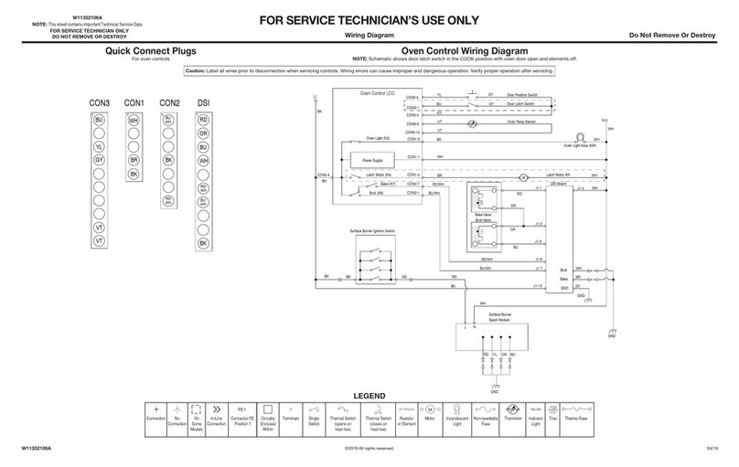
The wrung dlogrom 15found on
ci seporaiesheel in Ihe l~leroiure package
Thewirmg dlagrom con also be fcund on Ihe
underslde of Ihe sioroge drawer
Recommended
grounding
method
DO NOT, UNDER ANY CIRCUMSTANCES,
REMOVE THE POWER SUPPLY CORD
GROUNDING PRONG.
Foryourpersonol
sofet~. this oppl~once must
be grounded Thl5 appliance 15equ,pped w,th
o power supply cord having o 3~prong
groundlng plug To mlnimlze pc&s~bIe shock
hazard. the cord
musl
be plugged ~nlo
a
maling
3-prong. groun&g+pe WI!
receplocle. grounded I” accordance wllh Ihe
Nal~onal Electrical Code. ANSl/NFPA 70
1a1851edItIon’ and 01, local codes ond
ordinances [See Figure 1 ) If o mallng wolf
recepiacle is not available. 0 15Ihe personal
responslblllfy and obllgahon of the cuslomer
to have o properly grounded 3-prong wall
receptacle lnstallec by o quol~f& electrIcIon
Now start...
With range in kitchen.
1
Remove racks and Other ,IOdS from
n
lnsrde oven
2
Place one fool on the shlwlng
n
base. TIIIrange forward slighlly lo
free rear lec15 Gentlv lower rar~~e to floor TIII
range b&words ““Ill fronl legs are free
3
Remove shipping materials. lope
W and protective film from range
Do Not remove cardbard shipping base
01 this llme
4
Ad,ust the leveling legs 10 0
m panI where the range base does
not louch Ihe floor.
-10 prevenl lipping. mslall range
onli-lip bracket.
- Save these lnrtollotion Instructions.
5
n
If range will be installed
with a cabinet on one OI
Doll-f slaes. one ontr.lip bracket must
be installed.
9 Measure the distance
from the center of the
leveling leg to the furthest
pant that extends from
the back of the range.
Iliz
r
- Mark Ihe 61slance measured I” Step5 lrom
the rear of Ihe cabinet opening or wall of
the locatIon where the ronge will be
Inslolled. Addlllonal space may be needed
for go5 I~ne located behind the range
. Place one end of the anI!-tip brockel
on the flcoragoinsl the cabinef side 50
that the inside edge of the bracket 15
al,gned wlh the line drawn
Nole: If Ihere 15o cabinet on Only one
side. the onto-lip bracket must be
~nslolled oganst the cabinet.
GotoSleD6.
5
* If range lsNot installed
n
against a cabinet,
both anti-tip brackets must be installed
- Slade ronae into final
locahon iark o line on
the fka along sades Of
range about omie-half
me dlstonce from the
rear to the front
. Mark floor lo show where Ihe center Of
Ihe rear leveling legs ore on the right
a-d left sides of range. Slide range Oui
or loCatIon Draw o straight line
behveen the two marks
---
L \
,+s------e,\_-~ \
\
----.’ \I
l
Place an antl-lip bracket on the floor
Align the bracket with the lanes foflhe
right rear levelang leg ond the line drawn
for the right side of the range 05 5l?own.
Repeat fof Ihe left side of range using
the other anti-+,p bock&
Gotoslep6.
onll-flp brackel(sj. Remove brackel[s)
from
positIon
l
Contocl o quahfied carpel
installer for the best procedure lo
drill mounting holerlhrough your
lype of carpet.
. Before moving range across floor,
slide range onto cardboard or
hardboard.
Falure to follow these instruchons
may result in damage to lloa
CoverIng.
7 A!
To mount an&l
ip
,-.a ,I^^, C-J!
n
brockel(5) tow,, ,avv,,
drill o %z” hole at each
mounlmg screw location.
To mount anti.lip bracket(s)
to concrele or ceramic floor,
use o masonry drill bit to drill
He” holes at each mounting
screw lzcol~on Tap plastic
\
anchor5 Into mounllng holes
in floor wlh hammer
8.
Lane up holes
In onii-rip
brackel(s] “llh holes I”
floor Use the screws
provided lo los!en ant,-lip
brockel(s] lo f~cxr
PANEL B
