RCA RCA
XLR
1/4”
XLR
1/4”
MIC
LINE
CABLE
POWER
OU
este2
r
T
IN
OU
IN
OU
T
T
TIN
OSCILLATOR
SHIELDSHELL
SHIELDSHELL
1 SHIELD
2 TIP
3 RING
2
3
11 SHIELD
2 TIP
3 RING
3 RING
1 SHIELD
2 TIP
SHIELD
RING
TIP
OUTIN
TEST
1
1
este2
r
TINTRODUCTION
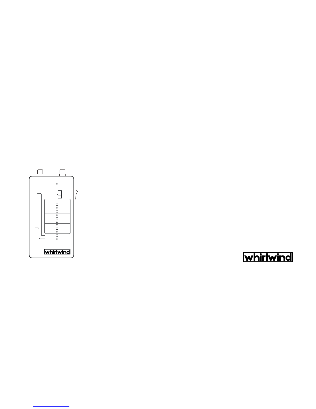
The whirlwind Tester 2 represents the next
generation of cable testers using digital
circuitrytocompletelytestany2or3conductor
cable regardless of its wiring configuration.
Simplyplugthecableinandthe Tester 2 will tell
youexactlyhowthecableiswired,immediately
ending guesswork with non-standard cables.
As with whirlwind's original Tester, hands are
freeto movethe cableat theconnector endsto
checkfor intermittentconnections.TheTester2
also outputs test tones for active testing. The
versatile Tester 2 is a must for people working
with many types of gear with a variety of wiring
configurations.
DESCRIPTION
The Tester 2 will check the continuity from
every connector pin at one end to every
connector pin at the other end, including the
XLR barrel and display the results of each test
path. The Tester 2 checks XLR, 1/4" TRS, 1/4"
TS, and RCA cables with any combination of
these plugs. The Tester 2 can also be used to
check cables where simultaneous access to
bothendsisimpossible,anexamplebeingwall
mounted or other permanent installations. The
tone oscillator outputs a 500 Hz test tone at
either mic or line level. The tone is a filtered
squarewave.
THEORYOF OPERATION
For each of the 3 conductors in a cable, the
Tester 2 has 3 LEDs for each conductor. The
digital circuitry in the Tester 2 sends a pulse
through each pin and monitors the 9 possible
connectionsthatcanexistontheotherendof
the cable. The Tester 2 then sends the pulse
down the second pin followed by the third. The
9 LEDs display the results and are updated
continuously throughout the cycle. Intermittent
problems are displayed on the LED display by
flickering lights when shaking the cable,
indicating exactly where the problem is in the
cable. The Tester 2 outputs 62.5 test cycles per
second. The nine test LEDs are various colors.
Green LEDs are used to indicate a good mic
cable. A standard good mic cable (wired 1-1,2-
2,3-3), will light all 3 green LEDs. Red LEDs are
used to indicate a short or phase reverse in a
cable. Yellow lights caution that there are
problems with a balanced mic cable or that the
cable is unbalanced. For unbalanced mic
cables, the Tester 2 will display the hot pin
(connected to tip of 1/4"), and how the non-hot
pin is wired (grounded or floating). With
standard 2 conductor 1/4" instrument cables
theTester2willdisplayringconnectedtosleeve
since the plug has a common ring and sleeve
connection.Inthis case the Tester 2 willnotonly
light the green LEDs for tip to tip and sleeve to
sleeve, but also 2 yellow LEDs for ring to shield
and shield to ring. The circuitry in the Tester 2
indicates if the shell of the XLR is connected to
it's corresponding pin 1. The test tone is on the
outXLR(male)andout1/4"connector.
TESTINGCABLES FROMONEEND
The Tester 2 can be used to test cables when
only one end is available by using a shorting
plug. This plug can be an XLR, either male or
female, with pins 1, 2 and 3 all connected
together or a 1/4" TS with the tip connected to
the sleeve. To test a cable, connect one end of
the cable to the Tester 2. The Tester 2 should
lightnoLEDsindicatingthatnothingisshorted.
TM
Next connect the shorting plug on the other
end of the cable. The Tester 2 should light all 9
LEDs indicating that there is continuity
throughout the cable and that the end is
shorted out. If both conditions are met the
cableisgood.
HIGHCAPACITANCE LIMIT
The Tester 2 will not function correctly with a
cable which has over .22 uF of capacitance
conductorto conductor.ForatypicalMICcable
(50pF/ft.)thelimitwouldbe4,400feet.
BATTERYINSTALLATION
The Tester 2 uses one standard 9 volt battery
(alkaline type will provide longer operation). To
install the battery, remove the four screws on
thebackandthe cover. Attach the battery to the
clip and place it in the compartment with the
foam next to the PCB. Replace cover and
screws.
POWERSWITCH PROTECTOR
A small bumper is provided which can be
attached near the power switch to prevent
accidentalturnon.