Whistler WBU-800 User manual

WIRELESS DIGITAL
BACKUP CAMERA
INSTALLS IN MINUTES
WBU-800
User Guide

2
Because the WBU-800 is truly wireless and does not tap into
your vehicle's transmission or backup light, you must tell the
unit when you are backing up. This also allows you to use your
back up camera to view behind the vehicle at any time.
When power is applied to the monitor an image will be
present for 60 sec by default or the user selected time, if the
screen goes blank and more time is required press the
for an image to return to the monitor.
Welcome
Thank you for choosing a Whistler product. We are dedicated
to providing products that represent both quality and value.
Please read the User Guide carefully before using this product.
If you have additional questions visit our website at
www.whistlergroup.com
or call Toll Free (800) 531-0004 / Tel (479) 273-6012,
8am to 5pm CT, Monday through Friday
to speak to a Customer Service Representative.
INTRODUCTION

3
TABLE OF CONTENTS
Components............................................................................ 4
Getting Started.................................................................... 5-6
Test the Camera / Pairing.................................................... 7-8
Assembly / Installation........................................................... 9
Attach to Vehicle .................................................................. 10
Mounting the Monitor.......................................................... 11
Setup...................................................................................... 12
Monitor Settings.............................................................. 13-15
Troubleshooting .................................................................... 16
Disclaimer .............................................................................. 17
Safety..................................................................................... 18
Care and Maintenance.......................................................... 19
FCC and IC Information................................................... 20-21
Specications ........................................................................ 22
Warranty Information...................................................... 23-27

4
COMPONENTS
1. Monitor
2. Camera with solar cells
3. Suction cup mount
4. Dash disk
5. Short machine screws (2)
6. Machine nuts (2)
7. Cushions (2)
8. USB Charge cord
9. Monitor power cord
10. Wrench
11. Pairing tool
12
3 4
5 8
9
10
6 7 11

5
GETTING STARTED
The WBU-800 is equipped with a built-in rechargeable lithium
battery and is connected with two solar panels that trickle
charge the built-in lithium battery when sunlight is available.
This will minimize or eliminate the need to manually charge
the unit during the year.
A USB charging port is provided to initially charge the battery
prior to mounting on your vehicle as well as to recharge if
needed. Your rechargeable battery when fully charged will
last for several months of average use with NO SUNLIGHT
(average use is defined as 4~6 times per day). With the
addition of sunlight, the solar cells will charge your battery
thereby extending the cameras ability to provide usage day
after day and month after month without requiring you to
recharge it manually.
Remove camera assembly from box and make sure all
components are included.

6
Charge The Camera
1. Connect the supplied USB cord to the micro USB port of
the camera assembly.
2. Plug the USB cable into any standard USB charger with an
output rating of 500ma or higher. The power switch will
illuminate when charging.
3. Charge the camera for 5 to 6 hours. When charging is
complete, illumination of the power switch will turn off.
4. Close USB door securely to ensure waterproof integrity.
GETTING STARTED
Under normal use, the camera maintains a charge with
exposure to sunlight. A battery status indicator is provided on
the monitor when the camera is in use.
NOTE: If vehicle will be stored for periods of time greater
than two months, please turn off camera using the switch
on the rear of the camera to the Off position to prevent the
battery from discharging.
USB door closed USB door opened
Micro USB port

7
TEST THE CAMERA / PAIRING
Test the Camera
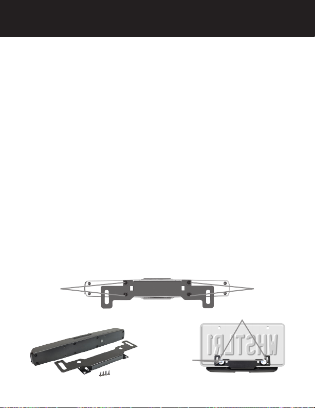
Prior to attaching the license plate to your vehicle, follow the
steps below to ensure pairing between the backup camera and
monitor.
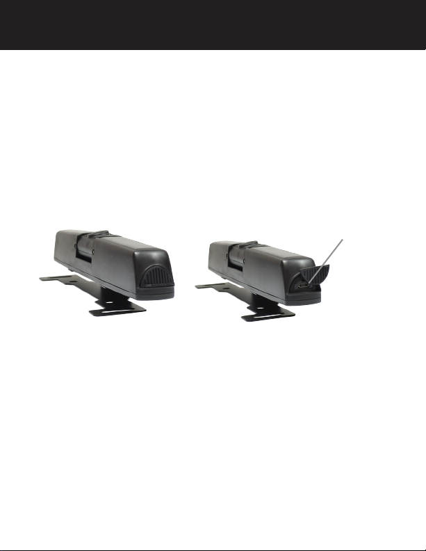
1. Slide the switch on the rear housing of the camera to the On
position.
2. With power applied to the monitor, the top right button will
illuminate to indicate the monitor is ON.
3. The top right button will blink briefly to indicate that it
is attempting to communicate with the camera. When
connected to the camera, the top right button will turn solid.
It may take a moment for the camera to begin sending the
video information. Allow time for the image to be displayed.
4. If no image appears, see Troubleshooting section of this user
guide. The image will time out in 60 seconds (unless user has
selected a different time out option) however, if you wish to
shut the image off manually, press anytime that video
is present to stop the video transmission and put the camera
back into the power conserve mode. (The top right button
will shut off when the timer expires)
5. The camera is equipped with 4 IR LEDs and a light sensor to
automatically illuminate during low light conditions. These IR
LED's are invisible to the human eye.
NOTE: If using a switched 12-volt DC Power port, it is not
necessary to power off the monitor.

8
TEST THE CAMERA / PAIRING
Switch
PAIRING MONITOR TO CAMERA
Your WBU-800 should automatically pair with your monitor.
If your monitor does not automatically pair with the camera
after initial charge, the following steps are to be used.
NOTE: There are two ways to pair the camera, select the one
that works best for your situation.
1. Turn off the camera using the switch on the back of the
camera. If already mounted to vehicle skip step 1.
2. Power on monitor.
3. Press then or to place cursor over SETUP, then
press power to select.
4. With PAIR icon selected, press power to select process.
5. This system can support 2 cameras, select the camera you
would like to pair. Camera 1 is the rear camera, Camera 2
is the front camera.
6. Using switch on back of camera, turn camera back on.
If your camera is mounted to your vehicle, use the pairing
tool to press and release the pair button located above
the Micro USB charge port.
Pair OK will be displayed when the pairing process is
completed.
2
PAIR
1
ON
PAIR
Pair button

9
Unit is assembled at the factory for mounting along top
edge of License plate. See Disclaimer section of this user
guide before mounting to vehicle.
NOTE: If you will be attaching the unit to the bottom of your
license plate, please follow the steps below:
1. Locate then remove the four screws holding the bracket
onto the camera.
2. Flip bracket, use the four screws to attach to back of
camera. The end result should be the USB door on the
right hand side as you face the camera when mounted to
the bottom of your license plate.
3. Secure the camera assembly to license plate using the short
machine screws and machine nuts. Cushions have been
included to avoid scratching your vehicles paint.
NOTE: Be sure to adjust the height of the camera assembly
to not impair readibility of the state, registration decal, stamp,
or other device indicating the month and year in which the
vehicles registration expires when securing to your license
plate.
ScrewsScrews
23
ASSEMBLY / INSTALLATION
Cushions
Machine Screws
1

10
ATTACH TO VEHICLE
Attach license plate to vehicle
Once you have tested the camera system and ensured the
pairing between the backup camera and monitor, you are
ready to reattach the license plate to your vehicle.
Use your OEM license plate mounting hardware when
mounting license plate to vehicle.
NOTE: Be sure to adjust the height of the camera assembly
to not impair readibility of the state, registration decal, stamp,
or other device indicating the month and year in which the
vehicles registration expires. Check local laws for compliance.
Adjust viewing angle
The camera angle should be adjusted to provide an optimal
view of objects behind the vehicle.
NOTE: Do not exceed 45 degrees down from central
position.
• Loosen the two screws below the camera a few turns.
(Do not remove.)
• To adjust the camera angle, tilt the camera to the correct
angle. (Do not force the camera)
• The camera should be adjusted to a horizontal position
relative to the ground, so as to provide optimal view of
objects behind the vehicle.
• Carefully tighten the 2 screws to prevent the camera
angle from moving during vibrations from driving.
Screws

11
MOUNTING THE MONITOR
Find a mounting surface inside the vehicle for the monitor
where it can be easily seen, and does not obstruct your vision
when driving.
NOTE: To maximize the effectiveness of the suction mount,
the mounting location surface temperature should be
between 50° and 100°F. Avoid application below 50°F.
NOTE: Before mounting the monitor, test the reception of
the camera signal in several selected locations within easy
reach as one may have better reception than another.
If mounting to the dashboard, the dash disk must be used to
ensure a smooth surface for the suction cup to attach.
1. Clean and dry the mounting surface before applying
suction cup or dash disk.
2. Press the suction mount against the mounting surface and
push the suction lock lever down. Make sure the mount is
attached securely.
3. Slide the monitor onto the monitor arm. The monitor angle
can be adjusted by loosening the monitor angle adjustment
knobs, tilting the monitor, then tightening the knobs.
4. Plug the monitor power cord into a 12-volt DC power port
inside the vehicle.
NOTE: See disclaimer section of this user guide.

12
Adjusting Monitor Settings
1. Press to bring up the menu options
2. Press or arrow to scroll through the different options
3. Press the to enter the options
4. Press the to increase or the button to decrease
settings
5. To change the view on the screen, scroll to then press
the to select camera 1, press to select 1 of 4 image
rotations. (It is best to have a video image displayed when
making this selection)
6. To exit, press the or wait for the 20 second timer to exit
automatically
Displaying Guidelines
To turn the guidelines On or Off, with video on the display
press for 3 seconds then release.
SETUP
Functions of the Buttons
Press to enable or cancel the video on the monitor.
Press for 3 seconds to turn on/off the backup assist
lines.
Press to enable/cancel the menu.
Press to move to or adjust a corresponding function.
Press and hold for 3 seconds to turn monitor off.Touch
to select a corresponding function.
Press to move to or adjust a corresponding function.

13
MONITOR SETTINGS
User selectable camera time durations
The WBU-800 has four user selectable camera time durations.
You may choose to set the monitor to stay on for 30, 45,
60, or 120 seconds by following the below steps when the
monitor is powered on:
1. Press the
2. Press the or to move the cursor over SETUP
3. Press the to select SETUP
4. Press the or to move the cursor over TIME-OUT
5. Press the to select TIME-OUT
6. Press the or to move the cursor over your preferred
time duration
7. Press the 3 times to save and exit or wait 20 seconds
and your selection will save and exit automatically
30
sec
120
sec
60
sec
90
sec
30
sec 45
sec
60
sec
120
sec

14
Menu Operations
Press main Menu and 4 options are available including
IMAGE PARAMETERS, IMAGE ROTATION, SETUP and
SOFTWARE INFORMATION. Press or to select
corresponding option, and then press the to enter the
option.
Select camera 1 for rear camera option or camera 2 for front
camera option if your model is such equipped.
In the example above the IMAGE PARAMETERS (Brightness,
Contrast, Color) Setting Interface is shown.
MONITOR SETTINGS

15
MONITOR SETTINGS
Brightness/Contrast/Color Settings
Press or on the interface to adjust the brightness as
shown above.
Image Rotation
Select IMAGE ROTATION, and then press to rotate or
mirror the image. (It is best to have a video image displayed
when making this selection). If you rotate the image on the
display an orange box with arrows will appear .
Setup
Select SETUP, press to enter SETUP Mode. Pairing mode
and camera time duration is found within SETUP menu.
Select Software Information
Press the to display the software version information.
Camera Selection
C1 indicates camera 1 (rear), C2 indicates camera 2 (front) if
your model is such equipped.
Battery Strength
The battery icon is on the top left corner of the monitor, and
indicates the relative capacity of the built-in lithium battery
when a video image is present.
Signal Strength
The signal strength of the received image is on the top right
corner of the monitor when a video image is present.

16
TROUBLESHOOTING
If the monitor does not turn on when power is applied:
• Check to make sure the power source is active (if your
12V power port is switched with the vehicle ignition, your
monitor will only work when the vehicle is running or the
key is in the ON position)
• Check to make sure the fuse and power cord are in
working order
• With power applied to the monitor, press button.
If the monitor does not display images within a few seconds
of pressing the button:
• The battery in the camera may be depleted and require
recharging
• The signal may be weak due to positioning of the camera
and monitor (try re-positioning the monitor to another
location)
If the video image is poor:
• Check that the camera lens is clean from road grime, snow,
or ice
If the video image is dark:
• Replace the vehicle's old backup and license plate bulbs
with new LED type bulbs
If the image appears to shake when the vehicle is moving:
• Check the camera mounting screws to the vehicle and
retighten if needed
• Check the camera tilt adjustment and retighten the screws
if loose.
If the video image does not last the user selected Time-Out
period:
• Re-check the Time-Out selection
• Recharge the battery in the camera

17
DISCLAIMER
The Whistler Digital Wireless Backup Camera is intended to
assist responsible drivers but it does not relieve a driver from
full responsibility for the operation of the vehicle. It is the
driver’s sole responsibility to avoid contact with any objects,
animals, or persons. By mounting and/or using the Whistler
Digital Wireless Backup Camera, you agree that you are solely
responsible for the operation of your vehicle and that The
Whistler Group is not responsible for any property damage,
personal injury, or loss of life that may result from the operation
of your vehicle.
Notice to Drivers in California and Minnesota:
State law prohibits drivers in California and Minnesota from
using suction mounts on their windshields while operating
motor vehicles. Other dashboard mounting options should be
used. (See California Vehicle Code Section 26708(a); Minnesota
Statutes 2005, Section 169.71).
Notice:
Some states or local governments may have regulations or
laws that restrict the use of anything that might impair the clear
view of a license plate. Check local laws for compliance. If your
state prohibits the use of anything that impedes the top of the
license plate, the camera can be mounted on the bottom of the
license plate as in the image below.

18
Safety
If at any time the backup camera assembly becomes
damaged, hot or begins to swell, discontinue use
immediately. Quickly and safely remove the backup camera
from the vehicle. Do NOT continue to handle, attempt to
use, or ship the damaged backup camera assembly. Failure
to follow these procedures can cause damage to personal
property or cause serious injury. Damaged or swollen
batteries in the backup camera assembly can be unstable and
very hot. DO NOT touch the batteries until they have cooled.
Dispose of the batteries in the manner required by your city,
county, state or country.
In the event of a crash, quickly and safely disconnect and
remove the backup camera assembly from the vehicle. Then
follow the previously listed safety procedures. If the internal
contents of the batteries included in the backup camera come
into contact with your skin, wash the affected area(s) with
soap and water immediately. If it comes into contact with your
eye(s), flush them with generous amounts of water for
15 minutes and seek medical attention. In the event of a fire,
a Class D, dry chemical fire extinguisher must be used.
SAFETY

19
CARE AND MAINTENANCE
Cleaning
Do not clean or wipe the Back-Up Camera with solvents or
chemical materials. If necessary, remove dirt or stains using a
soft cloth dampened with a mild detergent solution.
Fuse Replacement
1. Turn the cap on the tip of the power plug counterclockwise
(no tools needed).
2. Remove the cap, center pin and fuse.
3. Replace the fuse with a new 1-amp fuse.
4. Replace the center pin and cap. Turn the cap clockwise.
Disposal
The Back-Up Camera is designed to provide
years of service. The Back-Up Camera
should be recycled or safely disposed of at
a local recycling center.

20
FCC AND IC INFORMATION
IMPORTANT: FCC (Federal Communications Commission)
requirements state that changes or modifications not expressly
approved by Whistler could void the user’s authority to operate the
equipment.
FCC Part 15.19 Warning Statement
This device complies with part 15 of the FCC rules. Operation is
subject to the following two conditions: (1) this device may not cause
harmful interference, and (2) this device must accept any interference
received, including interference that may cause undesired operation.
FCC Part 15.21 Warning Statement
NOTE: The grantee is not responsible for any changes or
modifications not expressly approved by the party responsible for
compliance. Such modifications could void the user's authority to
operate the equipment.
FCC Part 15.105 Warning Statement
NOTE: This equipment has been tested and found to comply with
the limits for a Class B digital device, pursuant to part 15 of the FCC
Rules. These limits are designed to provide reasonable protection
against harmful interference in a residential installation. This
equipment generates, uses and can radiate radio frequency energy
and, if not installed and used in accordance with the instructions,
may cause harmful interference to radio communications. However,
there is no guarantee that interference will not occur in a particular
installation. If this equipment does cause harmful interference to
radio or television reception, which can be determined by turning the
equipment off and on, the user is encouraged to try to correct the
interference by one or more of the following measures:
• Reorient or relocate the receiving antenna.
• Increase the separation between the equipment and receiver.
• Connect the equipment into an outlet on a circuit different from
that to which the receiver is connected.
• Consult the dealer or an experienced radio/TV technician for help.
Table of contents
Other Whistler Automobile Accessories manuals