8
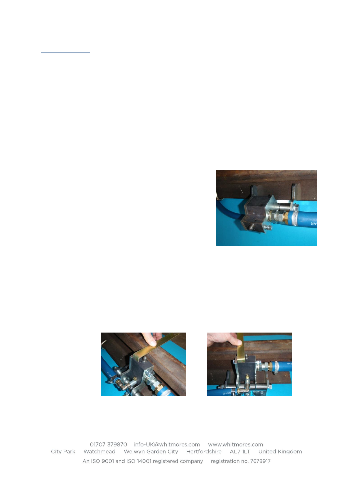
6.3.3 If the pump needs to be lowered then tap the pump
body down using the shaft of a hammer or strike the
face of the left side support bracket.
DO NOT STRIKE THE ALUMINIUM PUMP BODY
WITH A HAMMER AT ANY STAGE.
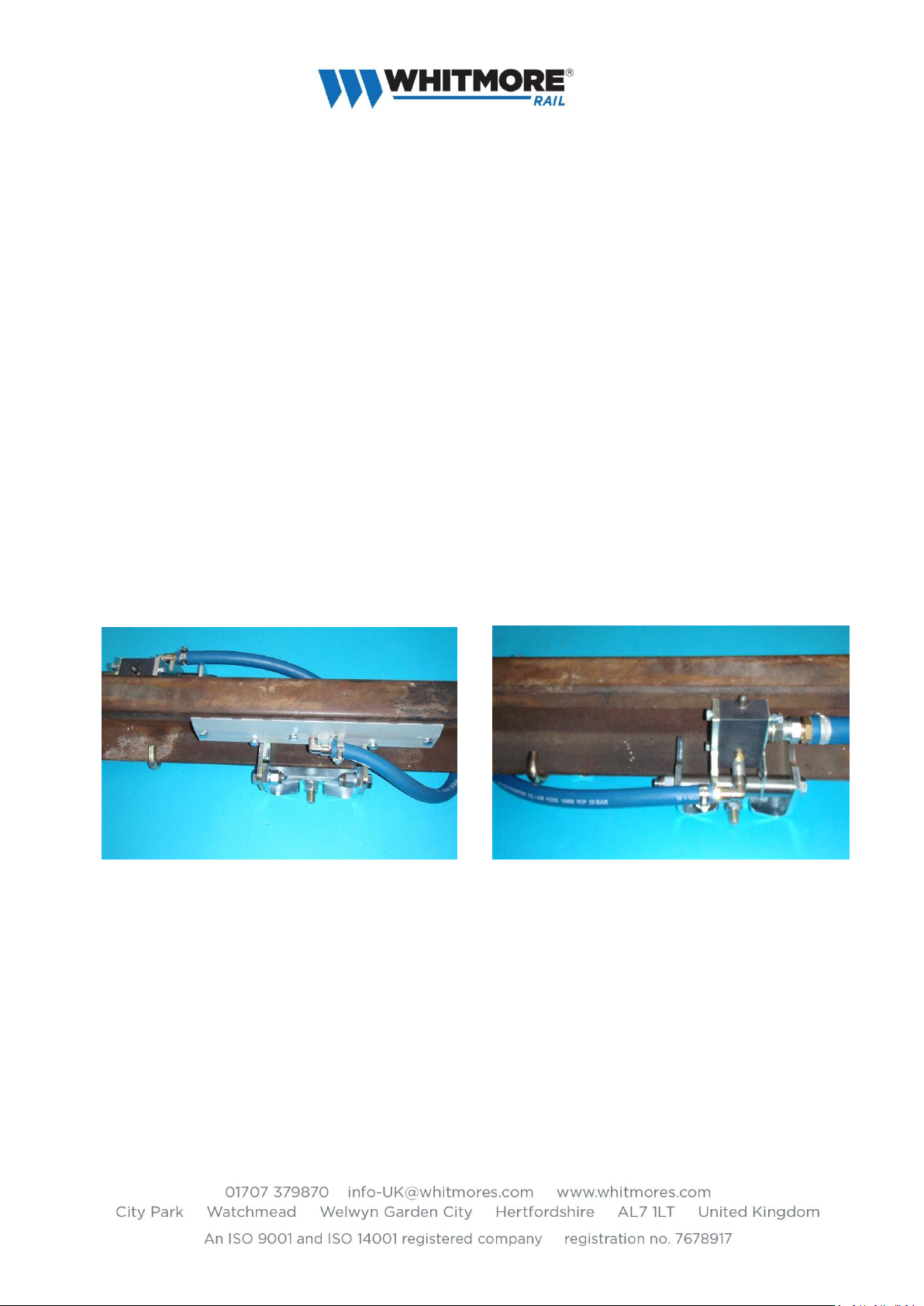
6.4 Fitting the Feed Hose and Reservoir
6.4.1 Slide the 25mm bore hose over the brass hose tail on
the pump and secure with the hose clip provided.
Tighten the hose clip.
6.4.2 Dig out the ballast so that the reservoir feed hose
curves away from the EasiPump and clears the rail clip
and sleeper without any kinks / restrictions to the
hose.
6.4.3 Bury the reservoir at an angle and approx. half its
depth to secure it in position, (see front cover picture).
6.4.4 Slide a feed hose clip over the open end of the feed hose and fit onto the angled pipe.
Tighten the hose clip.
6.4.5 The feed hose may need to be cut due to the local conditions.
6.4.6 Position the reservoir into space dug in the ballast ensuring that there are no kinks in the
feed hose.
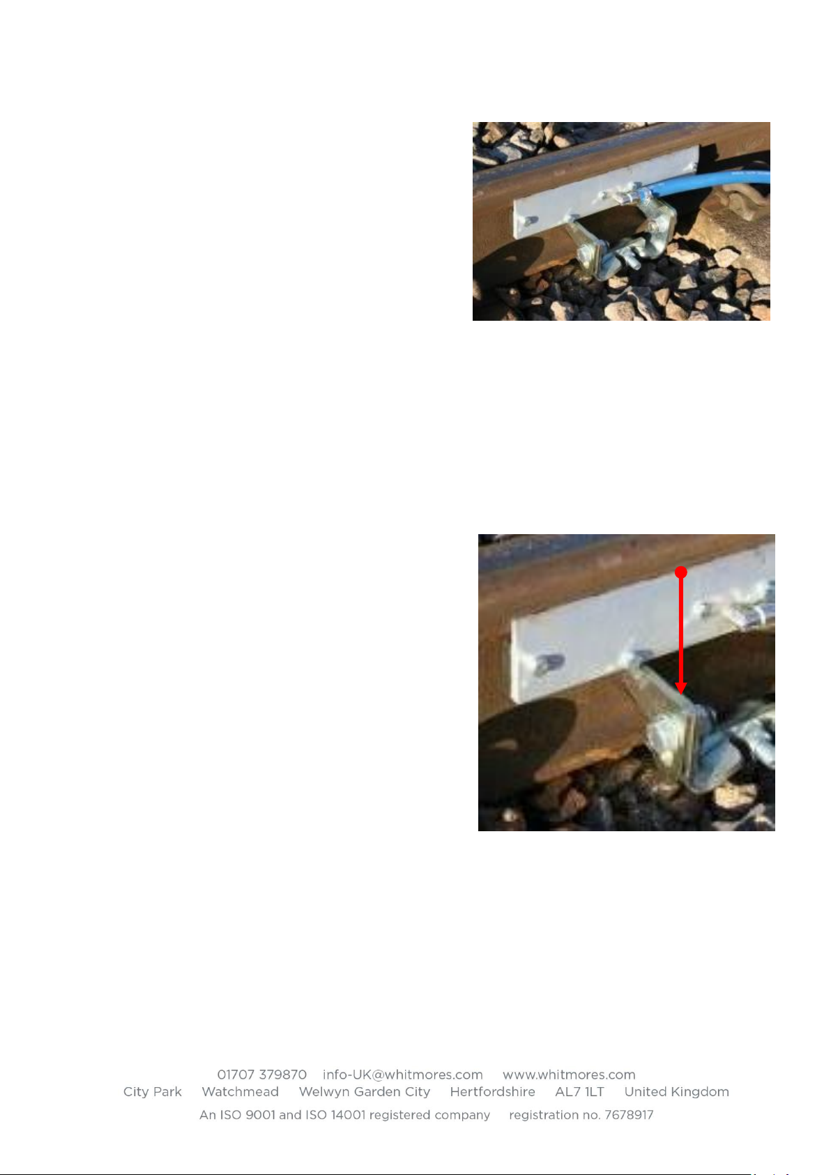
6.5 Setting the Pump and Plunger Height
6.5.1 The height of the plunger is adjusted by first loosening
the M8 lock screw on the side of the pump and then
rotating the adjuster screw in the top of the pump.
6.5.2 Loosen the M8 locking screw nut and then turn the
M8 hex screw a few turns, it is not necessary to
remove.
6.5.3 Using a suitable gauge / measurement device and a
2.5mm Allen key, raise the plunger to the initial
setting height of 0.5mm above the top of the rail.
Note: subsequent adjustment is usually necessary to
adjust grease output to suit local traffic / wheel
pattern. The typical range will be between 0 and 1mm
relative to crown of the rail head, in extreme cases it is
also permissible to set below rail head where worn
wheels are the cause of over greasing.
6.5.4 A setting gauge (Part No. LCS104-06) is available to
allow this measurement to be accurate.