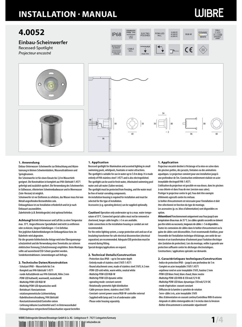
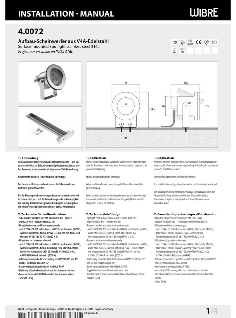
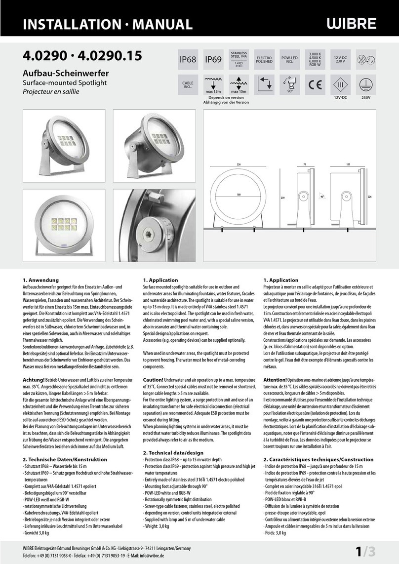
Wibre 4.2202 User manual

INSTALLATION · MANUAL
4.2202 | 4.2204 | 4.2206
Aufbau-Dock-Scheinwerferr
Surface Dock-Light
Dock-Projecteur en saillie
1. Anwendung
Aufbau-Scheinwerfer für den Einsatz auf Schiffsdocks, rauer See, für
Springbrunnen und hohenWasserfontainen.
Der Scheinwerfer ist für einen Einsatz bis 5 m Wassertiefe geeignet.
Da die Konstruktion komplett ausV4A-Edelstahl gefertigt ist, ist der
Scheinwerfer meerwassertauglich. Bei Verwendung von 250Watt
HIT ist der Einsatz auch außerhalb desWassers möglich.
Scheinwerfer ist vor Einfrieren zu schützen, das Wasser muss frei von
Metall angreifenden Bestandteilen sein.
Sonderkonstruktionen-/anwendungen auf Anfrage.
2. Technische Daten/Konstruktion
· Schutzart IP68 – Wassertiefe bis 5 m
· Komplett ausV4A-Edelstahl 1.4571
· Blende aus Bronze
· Befestigungsbügel um 180° verstellbar
· Metallhalogendampflampen
· wechseltemperaturbeständigem Sicherheitsglas
· Lieferung komplett anschlussfertig mit Vorschalt- und Zündgerät,
Leuchtmittel und 10 m Silikonkabel
· inklusive Dreh- und Standgestell
1. Application
Surface-mounted spotlight for use at ship-docks, raw se, in fountains and
high waterjets.
The underwater floodlight is water pressure tight for a depth up to 5 m.
Because of the special construction inV4A,316l marine grade stainless
steel, this floodlight is suitable for seawater.
When using HIT 250W a use outside the water is possible.
The floodlight must be protected against freezing in during winter time.
The water must be free of metal attacking ingredients.
Special constructions on demand!
2. Technical Details/Construction
· Protection class IP68 – up to 5 m water depth
· Entirely made of stainless steel 316Ti 1.4571
· Cover is made of bronze
· Mounting foot adjustable through 180°
· metal halogen vapour lamps
· toughened safety glass which is resistant to temperature changes
· Supplied completely ready for connection, with ballast device and
ignition device, light source and silicon cable (10 m)
· inclusive pivoting/standing frame
1. Utilisation
Projecteur en saillie pour utilisation dans les docks, pour des contraints
difficiles en mer, dans fontaines et waterjets..
Le projecteur est étanche à la pression jusqu‘à une profondeur de max. 5
mètres.
Sa construction en Inox V4A, 316l nous permet de lui utiliser aussi dans l‘eau
de mer. Quand on utilise des HIT 250 W installé hors de l‘eau.
Le projecteur doit être protégé contre le gel pendant l‘hiver.L‘eau ne doit pas
contenir de substances qui attaquent le métal.
Constructions sur mesure sur demande possible!
2. Technique/Construction
· Indice de protection IP68 – jusqu‘à une profondeur de 5 m
· Complet en acier inoxydable 316Ti 1.4571
· Enjoliveur en bronze
· Pied de fixation réglable à 180°
· lampes à iodure métallique
· verre trempé résistant aux changements de température
· Livré prêt à l’emploi avec ballast et amorceur, ampoule et 10 m de câble
en silicone
· incl. bâtis tournants
470
580
403
470
405
188188
380
490
270
WIBRE Elektrogeräte Edmund Breuninger GmbH & Co. KG · Liebigstrasse 9 · 74211 Leingarten/Germany
IP68
STAINLESS
STEEL V4A
1.4571
316Ti
230 V
max 5m 180° INCL
CABLE
INCL.

INSTALLATION · MANUAL
188 188
7
6
5
4
3
2
1
N L
8910
3. Installation/Montage
Zur Installation sind die Sicherheitsvorschriften zu beachten.
Befestigungsbügel ist entsprechend der Zeichnung 3.2 fest am Un-
tergrund zu verschrauben, hierfür sind ausschließlich entsprechende
V4A Edelstahlschrauben zu verwenden, da sonst Korrosion an den
Scheinwerferteilen entstehen kann.
NUR Silikonkabel verwenden, falls nicht im Lieferumfang enthalten.
Zum Anschluss des Kabels den Scheinwerfer laut Zeichnung 3.1.
öffnen und Glas (5), Dichtung (4;6), Reflektoreinsatz entfernen.
Kabelverschraubung am Scheinwerfer öffnen; Druckschraube (9), Sili-
kondichteinsatz (8) entfernen und über Silikonleitung (10) führen, in
Kabelverschraubung eindrücken und Druckschraube fest anziehen. 3.4
Achtung: Nur Silikonleitung mit Außendurchmesser von 9–13
mm verwenden, andere Durchmesser durch Austausch des Silikon-
dichteinsatzes möglich.
Achtung: Das verwendete Kabel muss komplet in einem
Kabelschutzrohr verlegt werden! Es darf nicht offen imWasser oder
im Erdreich liegen.
Einzelanschlussader entsprechend derVorschriften an Anschluss-
klemme elektrisch anschließen und Schutzleiterverbindung vor-
nehmen. Reflektor-/ Leuchteneinsatz montieren und Leuchtmittel
einsetzen (sofern nicht im Lieferumfang).
Silikonflachdichtungen (4;6), Glasscheibe (5), Blendring (3),
Unterlegscheiben (2), Schrauben (1) laut Zeichnung 3.1. auf
Scheinwerfergehäuse auflegen und kreuzweise gleichmäßig
verschrauben 3.3. (empfohlenes Anzugsdrehmoment 3,0 Nm). Es
ist auf gleichmäßigen, festen Sitz der Schrauben zu achten.
Diese sollten nach ca. 4Wochen Betrieb der Leuchten kontrolliert
und mit empfohlenen Drehmoment (3,0 Nm) nachgezogen werden.
Funktionsprobe des Scheinwerfers außerhalb des Wassers kurz
durchführen.
Befestigungsfuß am Scheinwerfergehäuse verschrauben und
Scheinwerfer auf Objekt ausrichten. Befestigungsfuß am Schein-
werfergehäuse nach Ausrichtung erneut fest verschrauben.
Achtung: Nur richtig eingelegte Dichtungen, Gläser, Abschlussblen-
den und richtig angezogene Schrauben sowie empfohlenes Kabel
und fest angezogene Kabelverschraubungen gewährleisten ein
Scheinwerferbetrieb nach IP68 unterWasser.
3. Installation/Mounting
For the installation and operation of this floodlight safety regulati-
ons must be observed at all time!
Mounting brackets and mounting angles must be fixed solidly on the
ground (see drawing 3.2), only stainless steel screws can be used,
otherwise corrosion on parts of the floodlight could occur.
Only use silicon cable, if not already supplied together with the
floodlights.
When connecting the cable to the floodlight, open the floodlight as
described on drawing 3.1 and remove glass (5), gaskets (4;6)
and the reflector.
Open the floodlight‘s cable gland, remove pressure screw (9), and
silicon gasket(8), pull everything along the connecting cable (10) and
press it into the cable gland, tighten the screw cable gland solidly. 3.4
Caution: Only use silicon cables with an exterior diameter of
9–13mm, other diameters can only be used, when changing
the silicon gasket.
Caution:The supplied cable must be completely installed in a
cable protection tube. It’s not suitable and therefore not allowed to
use it unprotected inside the water or in the ground.
Make electrical connection with the single wires, as well as the earth
conductor connection.
Insert the reflector, and put the bulb into it, if not already supplied
with the floodlight.
Mount silicon flat gasket (4;6), glass pane (5), cover frame ring
(3), washers (2), screws (1) as shown on drawing 3.1. onto the
floodlight and tighten them firmly crosswise. (torque =3 Nm). 3.3
Make sure that all screws are solidly and firmly placed!
Make a quick operation test outside the water. Observe and screw
the screws once again after one month of operation.(torque 3 Nm)
Screw the mounting foot onto the floodlight and orientate it towards
the object which needs to be illuminated.
Observe and screw the screws once again after one month of
operation.(torque 3 Nm)
Screw the mounting foot once again solidly onto the floodlight, after
orientation of the floodlight has been done.
Attention: Only correct seated gaskets, glass panes, cover frame
rings and tight screw connections ensure a watertight lamp housing
and an IP 68 permanent under water use.
3. Installation/Montage
Pour l‘installation veuillez respecter les instructions de sécurité.
Le projecteur doit uniquement être utilisé dans l‘eau. Avec des
wattages moins importants une utilisation hors de l‘eau est possible.
Fixer l‘étrier de montage ainsi que l‘angle de montage au fond du
projecteur (voir dessin 3.2), pour cette installation utiliser que
de vis InoxV4A, pour éviter le risque de corrosion.S‘assurer du bon
serrage de l‘ensemble!
Utiliser que de câble silicone, si ne déjà encore livré avec.
Pour le raccordement du câble au projecteur, ouvrir le projecteur
(voir dessin 3.1), enlever le verre (5), le joint (4,6) et le réflecteur.
Ouvrir le presse-étoupe du projecteur, enlever la vis de pression (9), joint
de pression (8), tirer l‘ensemble sur le câble en silicone (10), presser
l‘ensemble dans le presse-étoupe et resserrer bien la vis de pression. 3.4
Attention: Uniquement utiliser du câble en silicone avec un
diamètre extérieur du 9–13 mm, autres diamètres sont possibles si
on change le joint de pression.
Attention: Le câble branché au projecteur doit être installé
dans une gaine de protection. Il est déconseillé est en conséquence
interdit à utiliser le câble dans l’eau ou dans la terre.
Enfiler les gaines de silicone et faire le raccordement électrique,
mettre à la terre.Monter le réflecteur et insérer l‘ampoule, si elle
n‘était déjà livrée avec.
Poser joint en silicone (4;6), verre (5), anneau de l‘enjoliveur (3),
rondelles (2) et les vis (1) sur le projecteur 3.1, et serrer les vis en
croix et fort.(moment de serrage=3 Nm) 3.3 S‘assurer d‘une pose
de vis solide et équilibré.
Contrôler et revisser les vis après un mois d‘utilisation selon le
moment de serrage (3 Nm)
Faire un court test de fonctionnement du projecteur hors de l‘eau.
Visser le pied de fixation sur le projecteur et orienter le vers l‘objet
à éclairer.
Visser le pied de fixation encore une fois fortement après
l‘orientation du projecteur a été fait.
Attention: Seulement des joints, verres, anneaux des enjoliveurs
correctement installés et des vis bien serrés, ainsi que de câbles
conformes et des presse-étoupes bien serrés garantissent un
fonctionnement selon
IP 68 dans l‘eau.
.
2/4 WIBRE Elektrogeräte Edmund Breuninger GmbH & Co. KG · Liebigstrasse 9 · 74211 Leingarten/Germany
3.1 3.2
3.3
3.4

INSTALLATION · MANUAL
4. Wartung und Leuchtmittelwechsel
Scheinwerfer spannungsfrei schalten und Gehäuse wie oben be-
schrieben öffnen. 3.1. Leuchtmittel durch identisches austauschen
und Gehäuse lautVorschrift wieder verschließen 3.1; 3.3.
Hierbei Dichtungen zwischen Glas und Gehäuse und in der Kabel-
verschraubung auf Abnutzung oder Beschädigung überprüfen und
gegebenenfalls wechseln.Verunreinigungen und Ablagerungen auf
Glas oder Edelstahlteilen sind mit handelsüblichen Reinigungsmit-
teln zu entfernen.
5. Allgemeine Wartungshinweise
• Beim Reinigen darf die Leuchte nicht mit Metall angreifenden Rei-
nigungsmitteln in Berührung kommen. Der Einsatz salzsäurehal-
tiger Reinigungsmittel an und in der Nähe von Scheinwerferteilen
aus Edelstahl ist in jedem Fall zu unterlassen.
• Scheinwerfer und Einbaugehäuse regelmäßig reinigen, um
Fremdrostablagerungen zu vermeiden.
• Achtung: Keine Hochdruckreiniger verwenden.
• Strahler vor Einfrieren schützen, gegebenenfalls müssen diese
demontiert oder speziell geschützt werden.
•Verloren gegangene Schrauben dürfen nur durch Schrauben aus
V4A ersetzt werden.
• Je nach Beanspruchung (Höhe der Watttage) undWasserqualität ist
alle 5–8 Jahre einWechsel der Dichtungen (Glasscheibe,Verschrau-
bung, O-Ring) und der Kabel zu empfehlen.
6. Garantiebestimmungen
Folgende Garantiezeiten und Bestimmungen gelten vomTage der
Lieferung an:
• 24 Monate aufWIBRE-Scheinwerfer.
•Von den Garantieansprüchen ausgenommen sind Leuchtmittel und
LED Einheiten.
• Unter die Garantie fallen nachweisbare Material-, Konstruktions-
undVerarbeitungsfehler vonseiten des Herstellers.
• Für Schäden, welche durch Nichtbeachtung dieser Betriebsanlei-
tung, oder durch unsachgemäße Reparatur entstehen, können wir
keine Garantie übernehmen.
• Keine Garantie besteht, wenn die Installation nicht korrekt nach
den Bestimmungen vorgenommen wurde oder beiVerwendung
nicht geeigneter Leuchtmittel bzw. Anschlusskabel.
• Änderungen, die dem technischen Fortschritt dienen,
behalten wir uns vor.
7. Wichtige Hinweise
(Bei Nichtbeachtung folgender Punkte,
entfällt die Garantie.)
•Vor der Installation müssen alleTeile aufTransportschäden
überprüft werden!
• Jegliche Montage-, Installations- und Elektroarbeiten müssen von
qualifiziertem Fachpersonal durchgeführt werden.
• ZurVermeidung von Fremdrost nur Edelstahlwerkzeug verwenden!
• Die Kabellänge der Leuchten ist so zu wählen, dass man nicht im
Wasser oder feuchten Umgebung verlängern muss. Spätere Rekla-
mationen aufgrund dessen können nicht akzeptiert werden.
• Es dürfen nur originale Wibre-Betriebsgeräte verwendet werden.
• Ein Montageabstand von 10 cm zwischen Betriebsgeräten wird
dringend empfohlen, um wechselseitiges Erhitzen zu vermeiden.
• Anschluss der Betriebsgeräte muss stromlos erfolgen, da sonst
Entladungen im Netzteil zur Schädigung der LED führen können.
Es darf keine Primärspannung beim Wechsel der LED anliegen.
• Beim Anschließen der Leuchte die Polung beachten! Eine falsche
Polung kann dem LED-Modul schaden.
• Die Installation eines bauseitigen Überspannungsschutzes nach
DINVDE 0100-443, DINVDE 0100-534 und EN 62305 wird empfohlen.
• Bitte achten Sie auf Maßnahmen gegen ESD (Elektrostatische Entla-
dung) während aller Arbeiten am Scheinwerfer, Betriebsgerät und LED.
4. Relamping and Maintenance
Always dismantle and assemble the floodlight and open it as descri-
bed above 3.1.Change the lamp with an identical one and close as
described above. 3.1; 3.3.
Make sure that the gaskets in between glass and housing and the
ones in the cable gland are in a good condition, make sure that there
is no dirt on the gaskets, if damaged change them immediately.
Soiling on the floodlight should be removed frequently by using
commercial stainless steel cleansers.
5. General maintenance instructions
• During cleaning, the light may not come into contact with cleaning
agents that attack metals. The use of cleaning agents containing
hydrochloric acid on and close to the spotlight parts made from
stainless steel is to be avoided under all circumstances.
• Clean spotlight regularly, to avoid external rust deposits.
• Important: Do not use high-pressure cleaners.
• Protect spotlights from freezing; if appropriate, they may need to
be dismantled or specially protected.
• Lost screws or nuts may only be replaced by screws fromV4A.
• Depending on load (wattage) and water quality, we recommend
changing the seals (on the glass pane, fitting, O-ring) and cable
every 5–8 years.
6. Guarantee provisions
The following guarantee times and provisions apply from the day
of delivery:
• 24 months onWIBRE spotlights.
• Light elements are exempted from the guarantee claims
•The guarantee covers demonstrable material, construction and
processing errors made by the manufacturer.
•We can assume no liability for damage that arises through disre-
gard of this operating manual, or through improper repair.
• No guarantee exists if the installation has not been carried out
correctly in accordance with the instructions or if unsuitable light
elements or connection cables are used.
•We reserve the right to make changes in the interests of technical
progress.
7. Important information
(If the following points are disregarded,
the guarantee expires.)
• Before installation, all parts must be checked for transport damage!
• All fitting, installation and electrical work must be performed by
qualified specialist staff.
• Only use stainless steel tools to avoid external rust!
•The cable length of the lights should be chosen in such a way that
it is not necessary to extend in water or moist environments. Later
complaints resulting from this cannot be accepted.
• Only original Wibre operating units may be used.
• An installation distance of 10 cm between operating devices is
urgently recommended in order to avoid mutual heating up.
•The operating devices must be connected without power, as
otherwise discharges in the power supply may cause the LED to
be damaged. No primary voltage may be applied when changing
the LED.
• Note polarity when changing the lights!The wrong polarity can
damage the LED module.
• It is recommended that the customer install an overvoltage pro-
tection in accordance with DINVDE 0100-443, DIN VDE 0100-534
and EN 62305.
• Please comply with all anti-ESD (electrostatic discharge) measures
during all work on the spotlight, operating device and LED.
4. Maintenance et changement de lampe
Mettre le projecteur hors circuit et ouvrir le boîtier comme expliqué
ci-dessus (voir dessin 3.1) Changer l‘ampoule avec une ampoule
identique et serrer le projecteur comme indiqué.(voir dessin 3.1;
3.3.)
Observer soigneusement les joints entre le verre et le boîtier et ceux
au presse-étoupe, changer les s‘ils sont abîmés ou pourris.
Il est nécessaire de nettoyer régulièrement les parties en Inox et
de les débarrasser des dépôts et souillures avec un produit courant
d‘entretien de l‘Inox.
5 Consignes de maintenance générales
• Lors du nettoyage, la lampe ne doit pas entrer en contact avec des
produits de nettoyage attaquant le métal. L‘utilisation de produits
de nettoyage contenant de l‘acide chlorhydrique sur des ou à
proximité de pièces du projecteur en acier inoxydable est interdite
dans tous les cas.
• Nettoyer régulièrement les projecteurs afin d‘éviter des dépôts de
rouille extérieurs.
• Attention: n‘utiliser aucun appareil de nettoyage haute pression.
• Protéger les projecteurs du gel. Le cas échéant, ils doivent être
démontés ou être protégés de manière spécifique.
• Les vis ou écrous perdus doivent exclusivement être remplacés par
des vis enV4A.
• Selon la sollicitation (puissance) et la qualité de l‘eau, il est recom-
mandé de procéder au changement des joints (sur les vitres, les
raccords vissés et les joints toriques) et du câble tous les 5 à 8 ans.
6. Conditions de garantie
Les durées et conditions de garantie suivantes s‘appliquent à
compter du jour de la livraison :
• 24 mois sur les projecteursWIBRE.
• Les ampoules sont exclues de la garantie.
• Les vices matériels, de construction et de traitement justifiables
tombent sous la garantie du fabricant.
• Nous déclinons toute garantie pour les dommages occasionnés par
un non-respect de cette notice d‘utilisation ou par des réparations
inappropriées.
• Aucune garantie n‘est accordée si l‘installation n‘a pas été
effectuée correctement, conformément aux dispositions, ou en cas
d‘utilisation d‘ampoules ou de câbles de raccordement inadaptés.
• Nous nous réservons le droit de procéder à des modifications
intervenant dans le cadre des progrès de la technique.
7. Remarques importantes
(La garantie s‘éteint en cas de non-respect
des points suivants)
• L‘absence d‘avaries de transport doit être vérifiée avant
l‘installation !
•Tous les travaux de montage et d‘installation, ainsi que les travaux
électriques, doivent être réalisés par du personnel qualifié.
• Afin d‘éviter tout dépôt de rouille, utiliser exclusivement des outils
en acier inoxydable !
• La longueur de câble des lampes doit être choisie de telle sorte à ce
qu‘il ne soit pas nécessaire de la prolonger dans de l‘eau ou dans un
environnement humide. Toute réclamation ultérieure à ce motif ne
sera pas acceptée.
• Seuls des équipementsWibre originaux doivent être utilisés.
• Une distance de montage de 10 cm entre les équipements est
vivement recommandée afin d‘éviter un réchauffement mutuel.
• Le raccordement des équipements doit être effectué sans courant,
sans quoi des décharges dans le bloc d‘alimentation pourraient
entraîner une détérioration des LED. Aucune tension primaire ne
doit être établie lors du changement des LED.
• Lors du raccordement des lampes, respecter la polarité ! Une erreur
de polarité peut endommager le module de LED.
• L‘installation d‘une protection contre la surtension par le client
conforme aux normes DINVDE 0100-443, DINVDE 0100-534 et
EN 62305 est recommandée.
•Veuillez respecter les mesures contre la décharge électrostatique
durant tous les travaux sur des projecteurs, équipements et LED.
WIBRE Elektrogeräte Edmund Breuninger GmbH & Co. KG · Liebigstrasse 9 · 74211 Leingarten/Germany

INSTALLATION · MANUAL
4/4 WIBRE Elektrogeräte Edmund Breuninger GmbH & Co. KG · Liebigstrasse 9 · 74211 Leingarten/Germany
W744 Stand 12.16 - Technische Änderungen vorbehalten - Für Druckfehler übernehmen wir keine Haftung
Notes
This manual suits for next models
2
Other Wibre Spotlight manuals
Popular Spotlight manuals by other brands

Chauvet
Chauvet Intimidator Spot LED 250 user manual

Wetelux
Wetelux 84 28 91 instruction manual

Larson Electronics
Larson Electronics HML-5M-RC user manual

Havis
Havis CD-MAGNUM CD-CL-12 user manual

LIVARNO home
LIVARNO home 375304 2101 Operating and safety information

Philips
Philips SmartSpot 57966/48/16 user manual