manuals.online logo
Brands
  1. Home
  2. •
  3. Brands
  4. •
  5. WIDDER TOOLS
  6. •
  7. Test Equipment
  8. •
  9. WIDDER TOOLS HPIINS-10000 User manual

WIDDER TOOLS HPIINS-10000 User manual

WWW.WIDDDERTOOLS.COM®1
(203) 777-5395
WIDDER®TOOLS
HPIINS-10000 CALIBRATION SYSTEM
PRODUCT INFORMATION AND OPERATING INSTRUCTIONS:
Description: The HPIINS-10000 Calibration System is a compact, heavy-duty
digital gauge certification and calibration system. The included digital logger gauge is 0.1% full scale accurate
and is capable of storing up to 21,000 individual strings of pressure data
Maximum Pressure Input: 10,000 psi
Weight: 18 lbs.
IMPORTANT: FOR YOUR SAFETY BEFORE OPERATING THIS UNIT, READ THIS OPERATOR’S MANUAL
CAREFULLY AND COMPLETELY. LEARN THE OPERATION, APPLICATIONS, AND POTENTIAL HAZARDS
PETICULIAR TO THIS TOOL.
WWW.WIDDDERTOOLS.COM®2
(203) 777-5395
Table of Contents
A. Visual Inspection of HPIC Unit________________ Page 3
B. Connecting HPIC Unit ________________ Page 3
C. Bleeding the System ________________ Page 5
D. Digital Gauge Certification ________________ Page 5
E. Digital Gauge Calibration ________________ Page 6
F. Disconnecting HPIC Unit ________________ Page 7
NOTE: The following instructions are written specific to the WIDDER HPIC Unit and its
included digital gauge. However, these instuctions should apply to any similar hydrostatic test
system incorporating a digital gauge (see specific gauge manual for proper calibration steps.)
System Overview
Fine
Adjustment
System Pressure &
Data Logging Gage
Main Outlet
WWW.WIDDDERTOOLS.COM®3
(203) 777-5395
A. Visual Inspection of HPIC Unit
1. Check for damage to the overall unit
2. Check all components for damage
3. Check water inlet and outlet ports for
damaged/worn threads (clean out any debris)
4. Check analogue gauge for damage
5. Check digital gauge for damage
6. Turn on digital gauge and check
battery life (replace batteries if needed)
7. Zero the digital gauge now
B. Connecting HPIC Unit
1. Connect water supply to INLET of HPIC unit
(use PTFE tape to ensure a leak free seal)
2. Turn on water supply to flush the system until
water appears clean, then shut off water supply
3. Apply 2-3 wraps of PTFE tape to
NPT end of supplied adapter
4. Thread the adapter into the OUTLET of
HPIC unit until hand tight, then tighten with wrench
(depending on amount of wear on the threads,
more tightening may be required for a leak free seal)
ZERO Button
Battery Level
WWW.WIDDDERTOOLS.COM®4
(203) 777-5395
5. Connect one end of green test hose to
the outlet of Calibration System
6. Connect the other end of green test
hose to the adapter on HPIC Unit
7. Tighten both ends of green test hose firmly
(these are standard “M” type hose fittings)
8. Turn on Calibration System gauge and zero
(verify HPIC Unit digital gauge is still at zero)
9. Fully back off Air Regulator on HPIC Unit (counter-clockwise)
10. Close Air Shut-off Valve on HPIC Unit (perpendicular to airline)
11. Connect air supply line to HPIC Unit
12. Slowly open Air Shut-off Valve on HPIC Unit
13. Check the air system for leaks
ZERO Button
WWW.WIDDDERTOOLS.COM®5
(203) 777-5395
C. Bleeding the System
1. Open the Isolation Valve completely (counter-clockwise)
2. Open the Bleed Valve 1-2 full turns (counter-clockwise)
3. Run water through the system until no air appears
to be coming out of the bleed tube on HPIC Unit
(provide adequate container to catch bleed water)
4. Tightly close the Bleed Valve (clockwise)
5. Check for low pressure leaks in water system
6. NOTE: Both gauges should read street water pressure DO NOT ZERO ANY GAUGES AT THIS POINT
D. Digital Gauge Certification
1. Follow steps A-C then continue
2. SLOWLY increase system pressure using the
Air Pressure Regulator on the HPIC Unit
to about 2500 psi (the exact number is not critical)
3. Verify that the digital gauge in HPIC Unit
is within 25 psi of the Calibration System gauge
4. If the readings are within 25 psi, continue
(if the readings are more than 25 psi,
stop and move to instructions for Digital Gauge Calibration)
5. Continue increasing the pressure to about 5000,
7500 and 10000 psi, checking that the system pressure
readings are within 25 psi at each interval
6. If at any interval the readings are more than 25 psi,
stop and move to instructions for Digital Gauge Calibration
7. If gauge passes certification continue to directions for Disconnecting HPIC Unit
WWW.WIDDDERTOOLS.COM®6
(203) 777-5395
E. Digital Gauge Calibration
1. Follow steps A-C then continue
2. Back off the Fine Adjustment Knob on the Calibration System all the way (counter-clockwise)
then rotate 1 full turn clockwise (this allows a little pressure reduction if the pressures
in the following steps are exceeded)
3. Press the MENU button on the HPIC Unit gauge
4. Press the ▲(up arrow key) until the word CONFG appears
5. Press ENTER
6. Enter the user password if it has been programmed
7. Press the ▲(up arrow key) until the word RECAL appears
8. Press ENTER
9. The gauge will now display 0on the top line and flash
between INPUT and the unit of measure on the bottom line
10. Turn off the water supply and open the Bleed Valve
on the HPIC unit (this should allow the unit to have zero pressure,
use the Calibration System gauge to verify this)
11. Once at 0 psi, press ENTER on the HPIC unit gauge
(the 0 pressure point is now set)
12. The gauge will now display 10000 on the top line
13. Turn the water supply back on then close the Bleed Valve
14. SLOWLY increase the pressure in the system to about 9900 psi (using the Calibration System gauge)
It is very important that the pressure be SLOWLY increased and to NOT EXCEED 10000 psi
15. From 9900 psi use the Fine Adjustment Knob on the Calibration System to increase the pressure to
EXACTLY 10000 psi (give the system a few seconds to settle and perform any fine adjustments needed
to get the system to EXACTLY 10000 psi)
16. Be sure the calibration station gauge reads EXACTLY 10000 psi and press ENTER on the HPIC unit gauge
(the full-scale pressure point is now set)
WWW.WIDDDERTOOLS.COM®7
(203) 777-5395
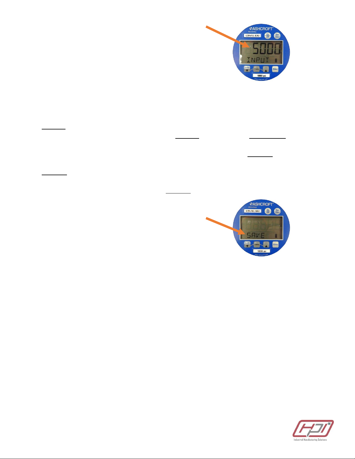
17. The HPIC unit gauge will now display 5000 on the top line
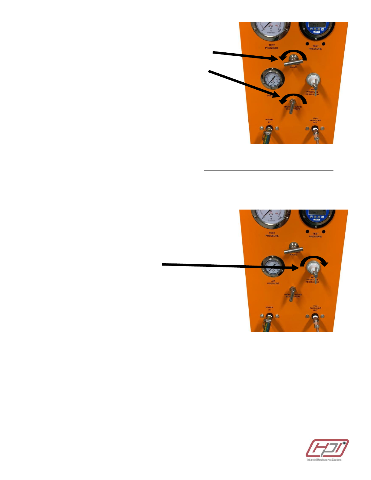
18. Back off the Air Regulator all the way (counter-clockwise)
19. Back off the Fine Adjustment Knob all the way (counter-clockwise)
then rotate 1 full turn clockwise
20. Open the bleed valve on HPIC Unit to relieve all pressure in the system
21. Close the Bleed Valve
22. SLOWLY increase the system pressure to about 4900 psi
Again, it is very important that the pressure be SLOWLY increased and to NOT EXCEED 5000 psi
23. From 4900 psi use the Fine Adjustment Knob to increase the pressure to EXACTLY 5000 psi (again, give
the system a few seconds to settle and perform and fine adjustments needed to get the system to
EXACTLY 5000 psi)
24. Be sure the Calibration System gauge reads EXACTLY 5000 psi and press ENTER on the HPIC unit gauge
(the mid-scale pressure point is now set)
25. The word SAVE will appear on the HPIC Unit gauge screen
26. Press ENTER to finalize the calibration process
27. Continue to Disconnecting HPIC Unit
F. Disconnecting HPIC Unit
1. Back off the Air Regulator all the way (counter-clockwise)
2. Disconnect the air supply line from the HPIC Unit
3. Turn off the water supply and open the Bleed Valve to relieve all pressure in the system
4. Disconnect the water supply from HPIC Unit
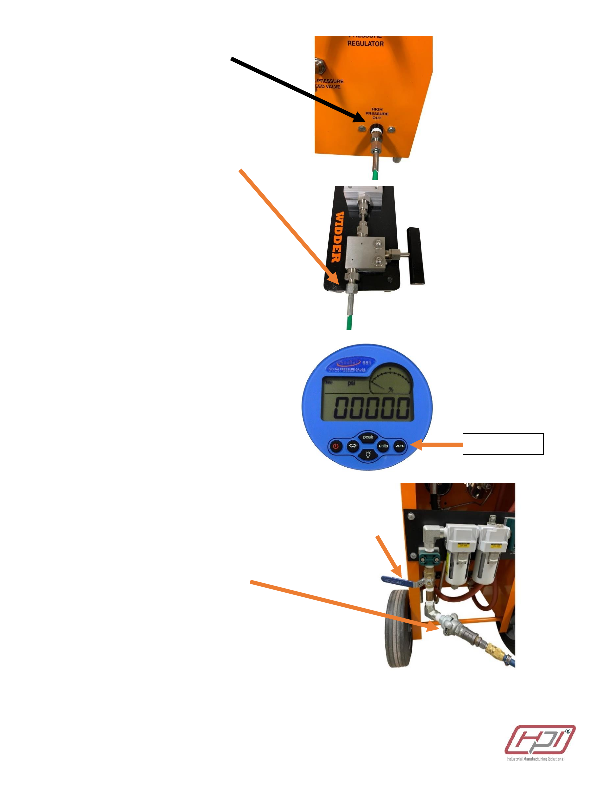
5. Using two wrenches disconnect the green hose from the outlet adapter in HPIC Unit
6. Remove the adapter from the OUTLET
7. If performing tests on multiple units it is acceptable to leave green hose attached to Calibration System
8. If needed, remove the green hose from the Calibration System with two wrenches (making sure the
adapter on the Calibration System does not spin)
WWW.WIDDDERTOOLS.COM®8
(203) 777-5395
WIDDER HPIINS-10000 Calibration System
WWW.WIDDDERTOOLS.COM®9
(203) 777-5395
WIDDER HPIINS-10000 Calibration System
Item
Description
Part #
Qty
1
Mounting Plate
PC-2001
1
2
Foot w/ Screw
PC-2007
4
3
Mounting Screw
PC-2005
4
4
Mounting Washer
PC-2006
4
5
Gage Bracket, Upper
PI7000-210
1
6
Digital Logger Gage
PC-1003
1
7
Gage Bracket, Lower
PI7000-211
1
8
Collar
PC-1022
2
9
Gland
PC-1023
2
10
Tube –Gage to Needle Valve
PC-1013
1
11
HP Adapter
PC-2003
1
12
Needle Valve
PC-1017
1
13
Valve Spacer
PC-2002
1
14
“M” Adapter
PC-2004
1
15
NPT Adapter
PC-1030
1
Accessories (not shown)
16
Data Cable
PC-1003-DC
1
17
Power Adapter
PC-1003-PA
1
18
Test Hose
PC-1019
1

Popular Test Equipment manuals by other brands

Hanna Instruments HI9810372 instruction manual

Hanna Instruments

Hanna Instruments HI9810372 instruction manual

sebaKMT T 26/1 A instruction manual

sebaKMT

sebaKMT T 26/1 A instruction manual

Atlanta BYK Cupping Tester manual

Atlanta

Atlanta BYK Cupping Tester manual

dlb AIJGO-22LCD instruction manual

dlb

dlb AIJGO-22LCD instruction manual

PMK dataTec FireFly FF-1500 manual

PMK

PMK dataTec FireFly FF-1500 manual

Hanna Instruments pHep+ HI98108 user manual

Hanna Instruments

Hanna Instruments pHep+ HI98108 user manual

REED R8802 instruction manual

REED

REED R8802 instruction manual

UEi ATLFSG instruction manual

UEi

UEi ATLFSG instruction manual

Kingfisher KI 2400 Series Training manual

Kingfisher

Kingfisher KI 2400 Series Training manual

Kongsberg TTC30 manual

Kongsberg

Kongsberg TTC30 manual

Viavi ALT-9000 Getting started manual

Viavi

Viavi ALT-9000 Getting started manual

Tektronix 7S11 instruction manual

Tektronix

Tektronix 7S11 instruction manual

IDEAL OTDR Quick reference guide

IDEAL

IDEAL OTDR Quick reference guide

Tektronix P7313 user manual

Tektronix

Tektronix P7313 user manual

Tektronix TCR801 Installation and safety instructions

Tektronix

Tektronix TCR801 Installation and safety instructions

HT EASYTEST user manual

HT

HT EASYTEST user manual

KINGSINE KS833 instruction manual

KINGSINE

KINGSINE KS833 instruction manual

Compliance West GFM-300A-DM instruction manual

Compliance West

Compliance West GFM-300A-DM instruction manual

manuals.online logo
manuals.online logoBrands
  • About & Mission
  • Contact us
  • Privacy Policy
  • Terms and Conditions

Copyright 2025 Manuals.Online. All Rights Reserved.