WiebeTech FORENSICK COMBODOCK User manual


PMS711 2cyan
85magenta
76yellow
10.25.12
CRU Mark
Page 2
1. Pre-Installation Steps 2
1.1 Box Contents 2
1.2 Identifying Parts 2
2. Setup 3
3. Menu Structure/Usage 3
3.1 Select Mode 3
3.2 View Drive Info 3
3.3 View Dock Info 4
3.4 HPA/DCO Auto 4
3.5 Create HPA/DCO 4
3.5.1 Set DCO Size 4
3.5.2 Set HPA Size 5
4. USB Mode Switch 5
Technical Specications 5
Drive Side
eSATA connection for connecting SATA drives
40-pin IDE header for external IDE cable attachment
Host Side
Dual FireWire 800 connectors
SATA power input
USB 3.0 connection
FireWire 400 connection
eSATA connection
Power
Power input from AC adapter
1.2 I dentifying Parts
Take a moment to familiarize yourself with the parts of
your new Forensic ComboDock. This will aid you in the
remaining steps.
4-pin square connection for drive power cable
USB Mode Switch
Table of Contents
Forensic Device User Advisory
Before using this tool for accessing sensitive data, verify the
write-blocking function of the product. This is easily done:
attach a known good formatted drive, and verify that the drive
mounts properly on your computer. Copy les to the drive.
Due to the “spoof writing” style of write-blocking employed
by this product, the les will appear to copy successfully.
Next, unmount and remount the drive The les that you
copied should not appear after the drive is remounted. If
they do appear, there is a problem with your forensic device,
and you should contact our support department for further
instructions.
CRU support may be reached through cru-inc.com or at
(800) 260-9800 (toll free)
1. Pre-Installation Steps
1.1 Box Contents
Please contact CRU if any items are missing or damaged:
Forensic ComboDock unit 1
AC adapter & power cord 1
USB 3.0 cable 1
FireWire 800 cable 1
FireWire 400 cable 1
eSATA cable 1
SATA drive attachment cable 1
IDE cable 1
Molex mini-t to legacy power cable 1
Metal drive plate 1
Packet of screws and bumpers 1
Quick Start Guide and Warranty Info 1

PMS711 2cyan
85magenta
76yellow
10.25.12
CRU Mark
Page 3
2. Setup
a) Attach protective metal drive plate to your 3.5”
hard drive. (This step is optional.) The purpose
of the bottom plate is to provide protection to your
drive electronics and aid heat dissipation.
b) If attaching an IDE/PATA drive, congure the
jumpers on the rear of the drive. The drive must
be set to the Master setting. Consult the
instructions or your drive (some drives display
conguration information on the drive’s label).
c) Connect Forensic ComboDock to the drive (or
adapter) using either the IDE ribbon cable for IDE
drives or the SATA data/power cable for SATA
drives.
d) If using an adapter, connect the drive to the adapter.
e) Attach the power cable to Forensic ComboDock and
to the drive. For SATA drives, the power cable and
data cable are combined into a single SATA drive
interface.
f) Connect the eSATA, FireWire or USB cable from
your computer into the corresponding port on
Forensic ComboDock.
g) Provide power to Forensic ComboDock. Use either
the included AC adapter or you can connect a
SATA power cable from inside a computer case.
This is useful if you wish to access a drive inside a
computer without removing it rst.
h) Turn on the power switch. The connected drive will
power up and Forensic ComboDock’s main menu
will appear on the LCD screen.
You are now ready to use Forensic ComboDock to access
the drive.
Write Block Indicator
LED (green)
3. Menu Structure/Usage of Forensic
ComboDock v5
Use the LCD and 4-button navigation interface to view
information about the drive and dock or adjust HPA/
DCO handling. On the 4-button navigation interface,
UP and DOWN allow scrolling through options, while
ENTER selects and BACK exits or returns to the
previous screen.
Forensic ComboDock’s menu consists of the following
screens:
3.1 Select Mode
Every time you switch Forensic ComboDock on, the
“Select Mode” screen displays. You can switch between
write-blocked or read-write modes. Write-blocked will
always be the default mode.
• Press UP or DOWN to toggle between the two
modes.
• Press ENTER to select the mode you want.
• If you select read-write mode, you will be prompted
to conrm your selection.
• Press ENTER to select the mode you wish to use.
• A “Standby” screen will briey display.
Forensic Combo Dock is now in the mode you selected.
3.2 View Drive Info
This screen displays information about the attached
drive.
• Press ENTER, and then use the UP or DOWN
buttons to scroll through and view the following info
about the drive.
Appearance on LCD Explanation
Disk Temp Temperature of the attached drive, measured in
degrees Celsius.
Capacity (MB) Capacity of the HDD, measured in megabytes.
Manufacturer Manufacturing company name of the HDD.
(continued)
Error
LED
(red)
Disk access
LED (amber)
Top of Unit
HPA/DCO
Indication
LED (green)
Navigation buttons Power switch
LCD
Power
input
status
LED
(green)
Power
output
status
LED
(green)
VIEW DRIVE INFO:
>
SELECT MODE:
WRITE-BLOCKED >

PMS711 2cyan
85magenta
76yellow
10.25.12
CRU Mark
Page 4
Appearance on LCD Explanation
Model number Model number of the HDD.
Serial number Serial number of the HDD.
Firmware Rev Firmware revision number of the HDD.
HPA size (MB) The size of the Host Protected Area of the HDD,
measured in megabytes/
DCO size (MB) The size of the Device Conguration Overlay of the
HDD, measured in megabytes.
Disk health Displays the S.M.A.R.T. health status of the drive.
Start/
Stops
S.M.A.R.T. information on how many times the
drive has spun up and spun down.
Power cycles S.M.A.R.T. information on how many power on/off
cycles the drive has underwent.
Bad sectors Number of bad sectors reported by the drive.
3.3 View Dock Info
VIEW DOCK INFO:
This screen displays information about your Forensic
ComboDock unit.
• From the “View Drive Info” screen, press the UP
or DOWN buttons to get to the “View Dock Info”
screen. Press ENTER.
• Use the UP or DOWN buttons to scroll through and
view the following info about Forensic ComboDock.
Appearance on LCD Explanation
Product Name
Brand name of the product (e.g. “Forensic Combo
Dock”).
Unique ID# A specic, unique number assigned to the unit for
identication, akin to a serial number.
Firmware ver. # Firmware version currently installed on the Forensic
ComboDock product.
3.4 HPA/DCO Auto
HPA/DCO Auto:
>
This screen allows you to congure the way Forensic
ComboDock will automatically handle hidden areas it
detects on drives during power up.
• From the “View Drive Info” screen, press the UP or
DOWN buttons to get to the “HPA/DCO
Auto” screen. Press ENTER.
• Press UP or DOWN to scroll through the four ways
Forensic ComboDock can handle HPAs and DCOs.
1) Ignore all - Detects and indicates their presence, but
does not remove them.
2) Temp Unlock HPA - Temporarily remove HPA only.
3) Perm Unlock HPA - Permanently remove HPA only
4) Unlock All - Permanently remove any HPA or DCO
• Press ENTER when your desired mode appears
on the LED. Forensic ComboDock will then set
your desired mode as the default.
3.5 Create HPA/DCO
You can create an HPA or DCO on the attached drive
only if you are in Read-Write mode.
If you try to create an HPA/DCO in Write-Blocked mode,
the screen will display “SUPPORTED IN R/W MODE
ONLY.” To create an HPA/DCO, cycle power on the unit
and switch to Read-Write mode.
3.5.1 Set DCO Size
This option is only available if no HPA exists on the
drive. It allows you to set a new size for DCO (Device
Conguration Overlay). Each drive can only have one
such area. Use the navigation buttons to select its
size. The disk capacity available to a computer will be
reduced by this amount. A value of zero means no DCO.
Values exceeding available capacity are not accepted.
• From the “View Drive Info” screen, press the UP or
DOWN buttons to get to the “Create HPA/DCO”
screen. Press ENTER.
• Press UP or DOWN to toggle between “Set HPA
size” and “Set DCO size” screens. When “Set
DCO Size” displays, press ENTER.
• A notication will appear on the screen that
continuing will end any data transfer. Make sure
no data is being written to or read from the drive,
then press ENTER.
• Use the UP, DOWN, BACK and ENTER buttons to
enter the size of the DCO that you want. Press
ENTER.
• Forensic ComboDock will ask you to conrm. If not
sure, Press BACK. If sure, press ENTER.
• Forensic ComboDock will then create the DCO.
When complete, you will be notied to cycle power
on the unit.
After Forensic ComboDock is turned off and back on, the
DCO exists on the connected drive.
VIEW DOCK INFO:
>
HPA/DCO Auto:
>
CREATE HPA/DCO:
>

PMS711 2cyan
85magenta
76yellow
10.25.12
CRU Mark
Page 5
3.5.2 Set HPA Size
From this screen, you can set a new size for HPA (Host
Protected Area). Each drive can only have one such
area. Use the navigation buttons to select its size. The
disk capacity available to a computer will be reduced
by this amount. A value of zero means no HPA. Values
exceeding available capacity are not accepted.
• From the “View Drive Info” screen, press the UP or
DOWN buttons to get to the “Create HPA/DCO”
screen. Press ENTER.
• Press UP or DOWN to toggle between “Set HPA
size” and “Set DCO size” screens. When “Set HPA
Size” displays, press ENTER.
• A notication will appear on the screen that
continuing will end any data transfer. If this is OK,
press ENTER.
• Use the UP, DOWN, BACK and ENTER buttons to
enter the size of the HPA that you want. Press
ENTER.
• Forensic ComboDock will ask you to conrm. If not
sure, Press BACK. If sure, press ENTER.
• Forensic ComboDock will then create the HPA.
When complete, you will be notied to cycle
power on the unit.
After Forensic ComboDock is turned off and back on, the
HPA exists on the connected drive.
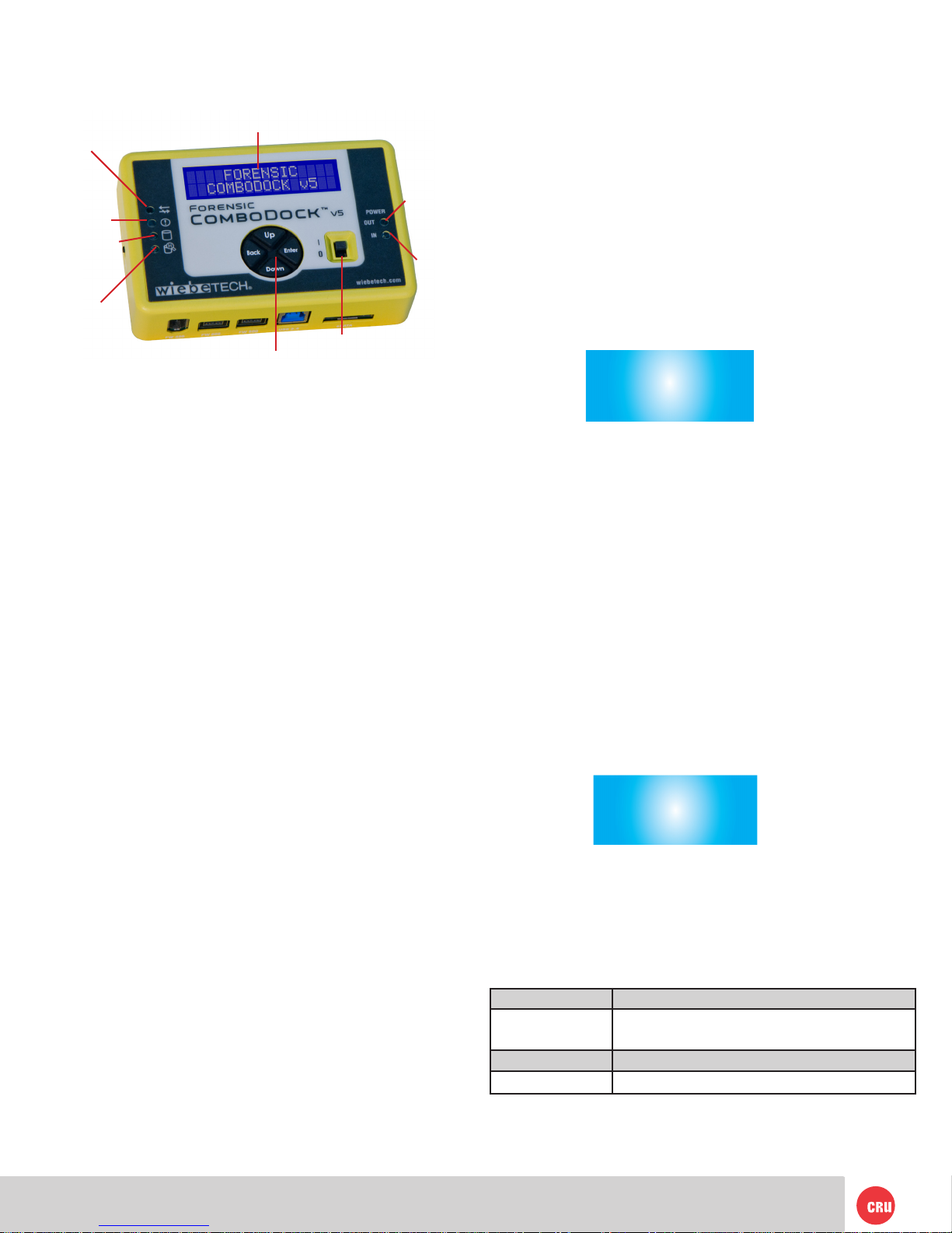
4. USB Mode Switch
There are two USB modes on Forensic ComboDock.
• USB 3.0 Mode: Use this mode when Forensic
ComboDock is connected to a USB 3.0 port on your
computer with a USB 3.0 cable (such as the cable
included with the product). If Forensic ComboDock
is used with a USB 2.0 port or cable and it is switched
to USB Normal mode, the dock will not function
correctly.
• USB 2.0 Mode: This mode ensures that Forensic
ComboDock is backwards-compatible with USB 2.0.
in this mode you can use any cable or USB port
type, but it will operate at USB 2.0 speed. USB
Admin mode should also be used when using CRU
applications (such as Forensic Software Utility) to
update the dock.
Technical Specs
© 2012, 2014 CRU Acquisition Group, LLC. ALL RIGHTS RESERVED
This User Manual contains proprietary content of CRU Acquisition Group, LLC (“CRU”) which is protected by
copyright, trademark, and other intellectual property rights.
Use of this User Manual is governed by a license granted exclusively by CRU (the “License”). Thus, except as
otherwise expressly permitted by that License, no part of this User Manual may be reproduced (by photocopy-
ing or otherwise), transmitted, stored (in a database, retrieval system, or otherwise), or otherwise used through
any means without the prior express written permission of CRU.
Use of the full Forensic ComboDock v5 product is subject to all of the terms and conditions of this User Manual
and the above referenced License.
CRU ™ , WiebeTech®, etc. (collectively, the “Trademarks”) are trademarks owned by CRU and are protected
under trademark law. This User Manual does not grant any user of this document any right to use any of the
Trademarks.
Product Warranty and Limitation of Liability:
Product Warranty
CRU warrants this product to be free of signicant defects in material and workmanship for a period of 3 years
from the original date of purchase. CRU’s warranty is nontransferable and is limited to the original purchaser.
Limitation of Liability
The warranties set forth in this agreement replace all other warranties. CRU expressly disclaims all other
warranties, including but not limited to, the implied warranties of merchantability and tness for a particular
purpose and non-infringement of third-party rights with respect to the documentation and hardware. No CRU
dealer, agent, or employee is authorized to make any modication, extension, or addition to this warranty. In
no event will CRU or its suppliers be liable for any costs of procurement of substitute products or services,
lost prots, loss of information or data, computer malfunction, or any other special, indirect, consequential, or
incidental damages arising in any way out of the sale of, use of, or inability to use any CRU product or service,
even if CRU has been advised of the possibility of such damages. In no case shall CRU’s liability exceed the
actual money paid for the products at issue. CRU reserves the right to make modications and additions to this
product without notice or taking on additional liability.
FCC Compliance Statement: “This device complies with Part 15 of the FCC rules. Operation is subject to the
following two conditions: (1) This device may not cause harmful interference, and (2) this device must accept
any interference received, including interference that may cause undesired operation.”
This equipment has been tested and found to comply with the limits for a Class A digital device, pursuant to
Part 15 of the FCC Rules. These limits are designed to provide reasonable protection against harmful interfer-
ence when the equipment is operated in a commercial environment. This equipment generates, uses, and
can radiate radio frequency energy and, if not installed and used in accordance with the instruction manual,
may cause harmful interference to radio communications. Operation of this equipment in a residential area
is likely to cause harmful interference in which case the user will be required to correct the interference at
this own expense.
In the event that you experience Radio Frequency Interference, you should take the following steps to resolve
the problem:
1) Ensure that the case of your attached drive is grounded.
2) Use a data cable with RFI reducing ferrites on each end.
Tested to comply
with FCC standards
FOR OFFICE OR COMMERCIAL USE
3) Use a power supply with an RFI reducing ferrite approximately
5 inches from the DC plug.
4) Reorient or relocate the receiving antenna.
Product name Forensic ComboDock v5
Drive Types
Supported:
• PATA/IDE 3.5”
• SATA 3G
• Hitachi 1.8” drives (with PATA Adapter 18-HIT-ZIF)
• Toshiba 1.8” drives (with PATA Adapter 18-TOSH)
• MacBook Air 2010 (with SATA Adapter MBA2010)
• MSATA (with SATA Adapter mSATA)
• PCIe PATA (with PATA Adapter mPCIe)
• PCIe SATA (with PATA Adapter mPCIe)
• PCIe USB (with PATA Adapter mPCIe)
Host (I/O) Ports FireWire 400: up to 400 Mbps
(1) pair of FireWire 800: up to 800 Mbps
(1) USB 3.0: up to 5 Gbps
(1) eSATA: up to 3 Gbps
Operating
system
compatibility
Windows XP or later
Windows Server 2003 or later
Mac OS X
Linux distributions that support the desired
connection
LEDs 6: Drive access, HPA/DCO detected, error, power
input status, power output status, write-block status
Warranty: 3 Years
Support Your investment in CRU products is backed up by our
free technical support for the lifetime of the product. If
you need to contact us for any reason, please visit
cru-inc.com/support or call us at 1-800-260-9800 or
+1-360-816-1800.
Table of contents