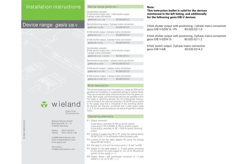
Wieland podis MCU FAC 3I/W 1.5 User manual

podis
®MCU FAC 3I/W 1.5
AS-i Motor starter
Art.-No. 83.222.0009.5
Operating Manual
Doc.-No. BA000628
Date: 04/2009 (Rev.A)
© 2009 Wieland Electric GmbH


1 | GeneralInformation
3
Wieland Electric GmbH | BA000628 (Rev.A) | 04/2009
Dear customer,
Congratulations on your new components from the
podis
remote automation system. You
are now the owner of an AS Interface technology product. It enables drive control in
industrial installations.
In order to learn more about the modules, familiarize yourself with this manual. It
contains all of the information and help settings required for proper operation of the
gesis
system in the building. If you still have questions or need additional help, our technical
experts will be happy to assist you using the contact options listed.
Hotline Technical Service (technical questions about accessories, functions, product features and
gesis
energy bus system and
podis
application options):
Tel.: +49 (0)9 51 / 93 24-9 98
AT.TS@wieland-electric.com
Saleshotline (for information about availability, lead
times and prices):
Tel.: +49 (0) 9 51 93 24-198
Fax: +33 1 30 32 07 17
info.adv@wieland-electric.com

GeneralInformation | 1
4
Wieland Electric GmbH | BA000628 (Rev.A) | 04/2009
1.1 Revision Listings
Document BA000628
Revison
Date
Author
Revision A
04/10/2009
Wieland Electric GmbH
1.2 Further Documentation, Software
The following documents supplement the existing version:
•Manual „AS-Interface Handprogrammiergerät“ (Art.-Nr. 83.206.2204.0)
You require the following software for project planning on a
podis
system:
•
podis
PLAN (Art. No. 95.502.1010.0)
The following documents are provided by the supplier:
•AS-i Master operating manual
•Drive operating manual
All brands mentioned and when indicated protected by third parties in this document are
subject to as such unreservedly, the respective valid legal requirements and right of
ownership of the respective registered owner.
Naming alone does not imply that the trade mark is not protected by third party
rights!
Documents of
Wieland
Documents
from
Brands
used

1 | GeneralInformation
5
Wieland Electric GmbH | BA000628 (Rev.A) | 04/2009
Content
1.1 Revision Listings ............................................................................................................................................. 4
1.2 Further Documentation, Software .................................................................................................................. 4
1.4 About This Operating Manual ......................................................................................................................... 6
1.5 Intended use ................................................................................................................................................... 7
1.6 Configuration, Programming, Installation Activation and Operation ............................................................... 8
1.4 Service and Maintenance ............................................................................................................................... 9
1.5 Prevention of Material Damage or Personal Injury ......................................................................................... 9
1.7 Hazards due to Electrical Energy .................................................................................................................... 9
2Device description ............................................................................................... 10
2.1 General data ................................................................................................................................................. 10
Function .................................................................................................................................................................. 10
2.2 Mechanical assembly/ Housing .................................................................................................................... 11
2.3 Operation and display elements ................................................................................................................... 11
2.4 Technical information ................................................................................................................................... 13
3Installation ........................................................................................................... 14
3.1 Mechanical installation ................................................................................................................................. 14
3.2 Electric installation ....................................................................................................................................... 16
4Activation and parameterization .......................................................................... 18
4.1 Preparations ................................................................................................................................................. 18
4.2 Motor starter control .................................................................................................................................... 19
4.2 Test mode..................................................................................................................................................... 26
5Operation ............................................................................................................. 28
5.1 Function terminal ......................................................................................................................................... 28
6Appendix ............................................................................................................. 30
6.1 Dimensions ................................................................................................................................................... 30
6.1 Technical data .............................................................................................................................................. 30
6.1 Ordering information .................................................................................................................................... 32

Device description | 2
6
Wieland Electric GmbH | BA000628 (Rev.A) | 04/2009
1.4 About This Operating Manual
This operating manual is an aid during installation, start up and
maintenance of the motor starter
podis
MCU 3I/W 1.5.
It contains information about how devices are programmed, configured and
parameterized.
This document contains the information necessary for proper use, the
technical data for the projects described therein.
podis
systems may only be installed by trained personnel and the
corresponding VDE regulations (German Association for Electrical, Electronic
& Information Technologies) are to be observed. Therefore, this operating
manual is aimed at technically qualified personnel (e.g. skilled electrical
workers, electrical engineers), who:
•as configuration and programming personnel, are familiar with the
safety concepts of automation technology, or
•as operating personnel, have been instructed in handling
automation technology equipment and are familiar with the
operation-related content of this manual, or
•as installation, activation and service personnel, have the necessary
training that enables them to service automation technology
equipment, and are authorized to install, earth and identify circuits,
devices or systems according to safety technology standards.
Specific prerequisites are:
•Basic knowledge of AS interface technology
•Basic knowledge about remote operating systems
This operating manual uses various safety notices that are assigned
according to the severity of a potential hazard:
DANGER
"Danger" indicates an imminently hazardous situation or state which, if not
avoided, will result in death or serious injury. The use of "Danger" is limited to
the most extreme situations.
WARNING
"Warning" indicates a potentially hazardous situation or state which, if not
avoided, could result in death or serious injury.
"Caution" indicates a potentially hazardous situation or state which, if not
avoided,
could result in minor or moderate injuries. "Caution" is also used to warn against
unsafe practices or obvious misuse, "Caution" is also used for situations which
may result in material damage without personal injury.
CAUTION
What Does
This Manual
Describe?
Who is this
operating
manual
intended for?
Safety
Notices

2 | Device description
7
Wieland Electric GmbH | BA000628 (Rev.A) | 04/2009
“Danger" or "Warning" are strictly used for cases which present a risk to life or limb.
Damage to property only falls into these categories if there is also a risk of personal
injury that corresponds to these levels.
1.5 Intended use
The
gesis
motor starter is an AS-i device on an energy bus for the connection and
protection of three-phase asynchronous motors.
Energy bus systems have been constructed using state-of-the-art-
technology and according to recognized safety regulations. However, when in
use they may still present risks to the life and limb of the user or third parties,
and the possibility of damage to machines, systems or other property.
The energy bus system must only be used when in proper working
condition, as well as according to its prescribed usage, with due regard given to
safety, awareness of any hazards and following the instructions contained in
the operating manual. Reliable and safe control operation implies proper
shipping, storage and installation, as well as careful operation.
Especially, failures that can affect safety are to be immediately corrected. In
order to use the automation systems as prescribed, the instructions outlined in
this operating manual must be followed for mechanical and electrical
installation procedures, as well as for activation and operation of the systems.
Never install damaged products and do not use them. Please contact the
transport company about any damages. During operation, plug connections are
not to be loosened or plugged into connected consumers.
During the projection, installation and implementation of energy bus systems
in line with machine supply and their control systems, the machine
manufacturer and user must therefore observe the safety regulations set out by
Machinery Directive 89/392/ EEC. National accident prevention regulations
apply in specific cases of operation. Observe applicable safety and accident
prevention regulations, e.g. machine protection guidelines, for respective cases
of operation. All safety devices on the controlled machine must be arranged in
such a way that they function independently of the controller. In all types of
system operations, EMERGENCY STOP equipment must remain operative
according to IEC 60204 (accord. to DIN VDE 113). In the event of an
EMERGENCY OFF, supply voltages must be disconnected from all equipment
that is controlled by the controller.
The motor starter is exclusively intended for automation applications in
industrial installations and machines. Other applications or use beyond this
scope is considered to be improper. The manufacturer assumes no
responsibility for any damage resulting from usage of this nature.
In order to use the automation systems as prescribed, the instructions
outlined in this operating manual must be followed for mechanical and
electrical installation procedures, as well as for activation and operation of the
systems.
All projection, program, installation, implementation, operation and
maintenance work in connection with
podis
electronic products may only be
executed by qualified personnel (e.g. skilled electrical workers, electrical
engineers). Configuring and programming
"Notice" indicates information that is directly or indirectly related to the safety
of personnel or property. It is not directly associated with hazards or hazardous
situations.
NOTE
Selecting
personnel and
qualifications

Device description | 2
8
Wieland Electric GmbH | BA000628 (Rev.A) | 04/2009
Personnel must be familiar with the safety concepts involved in automation
technology. Operating personnel must be trained in handling the control
system and familiar with the operating instructions. Installation, activation and
maintenance personnel must have a training background which authorizes
them to carry out work on the automation system.
Warnings are placed in appropriate places in the manual where there is
potential for obvious misuse or unsafe practices.
1.6 Configuration, Programming, Installation
Activation and Operation
The motor starters of the
gesis
and
podis
series are, in their application,
normally components of larger systems or installations in which machines are
controlled. During the configuration, installation and activation of
gesis
or
podis
systems as part of a machine control application, the machine
manufacturer and user must therefore observe the safety regulations set out by
Machinery Directive 89/392/EEC. In specific application cases, national
occupational safety standards apply, like e.g. VBG 4.0.
All safety devices on the controlled machine must be arranged in such a
way that they function independently of the controller. EMERGENCY OFF
equipment must remain effective in all operating modes of the controller. In
the event of an EMERGENCY OFF, supply voltages must be disconnected
from all equipment that is controlled by the controller.
A safety relay may be used for this purpose. Provision must be made for
the ability to properly initialize an interrupted control program again following
a power failure or interruption. During this time, any dangerous operating
states - even those occurring briefly - must be prevented. If necessary, an
EMERGENCY-OFF condition must be initiated. In order to ensure that a line
break on the signal side does not create an undefined state in the controller,
safety provisions must be made on the I/O coupling in terms of the hardware
and software. Items of safety equipment and their operating elements must be
installed in such a way that they are adequately safeguarded against
inadvertent operation.
All electrical power must be removed from the automation devices prior to
assembly or disassembly. Their design may not be changed.
The manufacturer assumes no responsibility for any damage resulting from
improper use.
NOTE
Foreseeable
misuse

2 | Device description
9
Wieland Electric GmbH | BA000628 (Rev.A) | 04/2009
1.4 Service and Maintenance
If measurements or tests need to be carried out on live equipment, the rules
and regulations set out by the applicable occupational safety standards (in
Germany, e.g. VBG 4.0) are to be observed. Only suitable electrical tools may
be used for this.
1.5 Prevention of Material Damage or Personal Injury
The device must only be operated in the voltage range between the minimum
and maximum values specified in the technical data. Otherwise, this could
result in malfunction or destruction of the devices.
Wherever failures in the automation equipment may lead to major material
damage or
even personal damage, additional external safety provisions must be made or
equipment
provided that will guarantee or force a pre-defined operating state, even under
failure conditions (e.g. independent limit switches, mechanical lockouts, etc.).
1.7 Hazards due to Electrical Energy
The user must ensure that unauthorized and improper intervention is stopped.
Personnel must be familiar with all the warnings, notes and measures
described in these operating instructions.
•Repairs to control components may only be carried by our authorized repair facilities.
Unauthorized opening and improper intervention or repairs can result in bodily harm or
material damage.
•Before opening the device, the power supply must always be disconnected.
•Control modules must only be replaced while the power is off. Removal and installation
must be carried out according to mechanical installation guidelines.
WARNING

Device description | 2
10
Wieland Electric GmbH | BA000628 (Rev.A) | 04/2009
2Device description
2.1 General data
Function
The three-phase electronic motor starter
podis
MCU 3I/W1.5 can be operated
as a direct and reversing starter on loads up to 1.5 kW. It starts three-phase
motor loads and monitors motor voltage. The
podis
MCU is an AS-i slave,
whose electronics are completely supplied with voltage from AS-i. The device
contains an electronic motor protection that is parameterised via the AS-i bus.
Up to three sensors can be connected via the M12 connector.
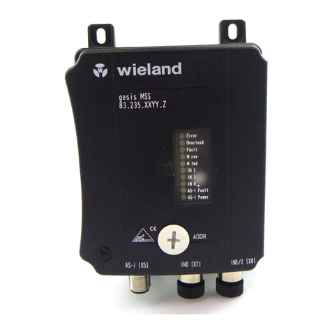
Figure 2-1:
podis
®MCU FAC 3I/W 1.5
2.1.2 Supply unit and drive
The motor starter is connected to the energy bus with a 5-pin RST connector
via a spur. Connecting the drive is just as easy via a 5-pin RST connector. The
AS-i bus is introduced separately on the motor starter with a M12 connector.
Thus, the drive is completely connected to the motor starter and the power
supply. All connection cables are available preconverted (see the reference
details in chapter 10, "Appendix"). RST connector technology makes the
podis
motor starter especially installation and maintenance friendly.
2.1.3 Sensors
Both 2 as well as 3 wire sensors can be connected on the three free inputs
of two M12 connectors via converted connecting cables. Sensors are
provided by the AS interface.
2.1.4 Addressing and testing
The motor starter can be addressed via the AS-i manual control unit
(83.209.2204.0), which is connected with the programmer cable
(83.209.2205.0) via the integrated address jack (Cinch). Motor currents can be
set using the handheld terminal for test purposes
.

2 | Device description
11
Wieland Electric GmbH | BA000628 (Rev.A) | 04/2009
4
5
6
2.2 Mechanical assembly/ Housing
The
podis
MCU is a mono-block device that is not permitted to be opened. It is
functionally divided into an upper and lower part.
The electronics for drive control and for input and output, including bus
communication, are found in the upper part of the housing.
The connection technology for the supply unit and motor are found in the lower
part of the housing.
2.3 Operation and display elements
2.2.1 Overview
2 1
3
Figure 2-2: Overview of functional components
1
LED display (status, error)
2
Addressing jack
3 X5 AS-i connection
4 X7, X8 Input Sensors
5 X1 3-phase input voltage (400 V)
6 X4 3-phase motor output
2.3.2 3-phase connectors
Input X1
(male, black)
Motor output X4
(female, black)

Device description | 2
12
Wieland Electric GmbH | BA000628 (Rev.A) | 04/2009
2.3.3 Outgoing circuits to the actuator X10 (M12)(View from outside onto the jack contacts)
Der
gesis
MCU is addressed via a manual control unit. The AS-i manual programming
device (Art.no. 83.209.2204.0) connected to the address jack of the
gesis
MCU
(programming cable, Art.no. 83.209.2204.0 is required for this). Additional information
about addressing can be found in chapter 5.1 "Setting the As-i slave address on
podis
MCU“.
2.2.2 Digital inputs X7, X8, X9 (M12)(View from outside onto the jack contacts)
5
(*) The supply for the digital inputs on X7, X8 and X9 is handled from the AS interface
2.3.4 LED displays
Information about the status of the field distributor can be found via the status
LED on the housing cover. See chapter 8, "Operation".
Detailed descriptions and possible trouble shooting can be found in section
8.1,"Function control".
NOTE
•L1 is hardwired to T1 and is not connected.
•Phases L2 and L3 are connected via Relais/TRIACS as follows:
–Turning direction right: L2 to T2 and L3 to T3
–Turning direction left: L2 to T3 and L3 to T2
NOTE
Pin Brief description Remarks
1 AS-i + AS interface +
3 AS-i - AS interface -
No.
Color Name Meaning E/A Bit
1 Red Error Error
2 Yellow Overload Overload
3 Yellow Fault Malfunction
4 Yellow M rev CCW rotation of motor
5 Yellow M fwd CW rotation of motor
6 Yellow IN2 Input IN2
7 Yellow IN1 Input IN1
8 Yellow IN0 Input IN0
9 Red AS-i Fault Fault AS-i
10 Green AS-i Power Voltage supply ok.
To be able to ensure compliance with protection type IP 65 all connections not
being used must be fitted with protective flaps!
NOTE
1
2
4
3
Pin assignment in
digital inputs
Pin X7 X8 Remarks
1 AS-i voltage AS-i voltage 24 V-Sensor supply unit(*)
2 IN0 IN2 switched input
3 0 V 0 V 0 V-Sensor supply unit(*)
4 IN0 IN1 switched input
5 not allocated not allocated not allocated

2 | Device description
13
Wieland Electric GmbH | BA000628 (Rev.A) | 04/2009
2.4 Technical information
2.4.1 Installation dimensions
2.4.2 Block diagram
L1 1
L2 2
X1 L3 3
L2 T2
A
A
L3 T3
1
T1
2
T2
3 T3 X4
As-i +
1
X5
As-i -
3
24V 1
IN0 2
24V
0V
X7 0V 3
X8
IN0 4
nc 5
24V 1
IN2 2
0V 3
IN0
IN2
IN1
AS-i / μC
IN1 4
nc 5
LED's
ADDR
ADDR
Addressing jack
X5 M12, A-coding
X1
Flat cable adapter
X7, X8 M12, A-coding
X4
RST20i5 black
nc not allocated

Elektrische Installation | 3
14
Wieland Electric GmbH | BA000628 (Rev.A) | 04/2009
3Installation
3.1 Mechanical installation
The
podis
MCU motor starter simply plugs into a 7-pin flat cable outlet, FCS 4 7 SI BU.
Assembly of the flat cable outlet is described as follows.
Requirements
The substructure must be:
•even,
•vibration-free and
•buckling
resistant
Installation dimensions
a
c
a
a
b b
Figure 3-1
a – Mounting holes; b – Screws for the
podis
base; c – Contact screws
NOTE
Only the boreholes provided may be used for installation on a level surface.
Additional boreholes at other places are not permitted!
Four M4 screws (not included) are required for fastening the device to a level surface.
Proceed as follows for installation on the substructure:
1. Screw the device to the base plate with two fastening screws M4 [a] (see drawing in
"Conductor assignments").
Use washers.
Required
accessories
Installation:
Procedure

3 | Installation
15
Wieland Electric GmbH | BA000628 76| 04/2009
1. To insert the flat cable into the base, open the screws [b] on the top edge. Tilt the base
and insert the flat cable according to the code. Then tilt back the
podis
CON base and
tighten both screws (torque 1.2 Nm).
2. Screw in all (also unneeded) contact screws into the flat cable (Torque 1,0 Nm).
Insert the
podis
MCU in the flat cable outlet and arrest the locking lever.

16
Elektrische Installation | 3
Wieland Electric GmbH | BA000628 (Rev.A) | 04/2009
a
c
e
d
3.2 Electric installation
b
Figure 3-2
a– Plug programming jack; b– AS-i connection; c– Digital outputs; d– Energy bus connector;
e– Motor connection plug
3.2.1 Power line connection
Proceed as follows for connecting the field distributor to the energy bus:
•All electrical installations and connection may only be executed by qualified
electricians.
•Applicable safety and accident prevention guidelines are to be observed.
•The plug connectors may never be subjected to strain or removed.
•All flat cables are to be disconnected from the power supply before opening
and removing the upper part of the housing.
•When wiring extra-low voltage circuits together with low voltage circuits in
one cable, the cable is to be protected from mechanical damage in
dangerous areas with e.g. cable conduits, steel pipe or equal protection.
WARNUNG

17
Wieland Electric GmbH | BA000628 76| 04/2009
3 | Elektrische Installation
3.2.2 Drive connection
•First, connect the free end of the connection cable (Art.no 96.453.xx84.1) to the drive.
Follow the documentation provided by the drive manufacturer for this. Allocation of
RST connector contacts to the cables is as follows
(see section 3.3.1, "3-phase connectors"):
Male contact
assignment
1
L1
2 L2
3
L3
PE
•Plug the connector cable RST plug e into the motor connector jack (see illustration 2-2).
Make sure that plug-side lockout C latches in the connector jack.
3.2.3 AS interface connection
Connect AS-i interface X5 (see illustration 2-2) of the
gesis
motor starter via the yellow
AS-I cable to the AS-i network.
Connection via the AS-i connection clip and the AS-i spur are recommended. Wieland
Electric GmbH provides both parts as accessories (see appendix for ordering information).
3.2.4 Sensor connection
On the
podis
motor starter, digital inputs can be added on the AS interface via the
M12 jacks X7 and X8 (see illustration 2-2 as well as the block diagram).
Order.-No.
AS interface
(externally
via M12)
Digital Inputs
M12
Digital inputs
from
the drive
Digital outputs
M12
Digital outputs to
the
consumer
83.234.0009.5 1 3 – – –
Interlocking connections (power line, motor connector) cannot be loosened
without tools.
NOTE
Unused connections have got to be provided with M12 end caps (Illustration 3-2,
B), in order to maintain a protection class of IP 65.
WARNING

Activation andparameterization | 4
18
Wieland Electric GmbH | BA000628 (Rev.A) | 04/2009
4Activation and parameterization
4.1 Preparations
4.1.1 Setting the AS-i slave address on
podis
MCU
The slave address has got to be set on the
podis
MCU after its mechanical and electrical
installation.
Allocation of the AS-i slave addresses wanted is carried out either via the AS-i master
orvia an AS-i manual control unit (see the AS-i master or AS-i manual control unit
operating manuals).
The
podis
MCU device has a default address of "0" (standard according to AS interface
specifications).
Proceed as follows for setting slave addresses with the AS-i addressing device:
1. Remove the plug (see section 3.2) from the address jack.
2. Plug the address cable (phone jack) of the address device into the motor starter
address jack.
3. Enter the address. Refer to the address device operating manual.
4. Loosen the address cable and cover the address jack with the cap.
4.1.2 Manual operation / On-site operation
AS-i slave inputs can be read and/or the outputs set with the AS-i manual control unit.
Thus, simple pre-activation is possible, without the
podis
MCU being already tied to a
control system.
If operating mode "Read and write data" is selected with the address device, the
motor can be controlled by setting output bits.
Additional information about test mode can be found in section 5.4 "Test mode".
Procedure

4 | Activation andparameterization
19
Wieland Electric GmbH | BA000628 (Rev.A)| 04/2009
4.2 Motor starter control
4.2.1 Process image (cyclical data exchange)
The following bits are set:
Process outputs
Function
BIT 3
BIT 2
BIT 1
BIT 0
0
0
0
0
Motor stopp
0
0
1
0
Enable right (*), motor stop
0
0
1
1
Motor right
0 1 0 0 Enable right (*), motor stop
0
1
0
1
Motor left
1
0
0
0
Acknowledgement (with start error and after end
of
x
x
x
x
reserved, motor stop
(*) The direction is enabled without delay (pause on reverse) and thus, a higher switching frequency is
made possible with this function.
In cyclical slave-master mode, the state of three sensor inputs and a
"Ready for operation" message from the drive were reported according to the binary
table of the AS-i input bits:
Process
inputs
Input PIN
X7 X8
Function
BIT 0
2 und 4
(are jumpered)
-
„1“(HIGH)
BIT 1
-
4
„1“(High)
BIT 2
-
2
„1“(High)
BIT 3 - - „1“= starter ready
(no starter error)
4.2.2 Write parameter (wr_74_parameter)
The expanded slave profile enables cyclic data exchange of 4E/4A bit and additionally offers
the option of reading parameter data (READ PARAMETER STRING) and diagnostic data (READ
DIAGNOSTIC STRING) and to write parameter data for AS-i slave WRITE PARAMETER STRING).
The following function parameters and values must be passed by the user of the
podis
MCU. These values serve for setting motor protection and for parameterization of the
module behavior. The passed data is checked for plausibility and retained in Flash.
Index Type Default Meaning Value range
hex hex dec
hex dec
0020 INT16 0190 400 Nominal current motor
1-076C 1-1900
0021 INT16 0100 256 Nominal current motor
see table
0022 INT16 000A 10 Current symmetry (%) 0-0064 0-100
0023 INT16 0064 100 Pause on reverse (ms) 0020-FFFF 32-65535
0024 INT16 FFFF 65535 Configuration parameter
bit coded, see table
0025 INT16 07D0 2000 Measuring constant (ms)
3000-FFFF 12288-65535
0026 INT16 0064 100 Deactivation constant 1-09F6
(see table) 1-2550
0027 INT16 0000 0 reserved
Cyclical data
exchange:
Slave D Master
Cyclical data
exchange:
Slave D Master

Activation andparameterization | 4
20
Wieland Electric GmbH | BA000628 (Rev.A) | 04/2009
Parameter strings are generally structured as follows:
Byte
Parameter string
When writing parameter strings (WRITE PARAMETER STRING), the first two byte are
interpreted as start index (this does not apply during reading). The following byte (max.
16) are data that are written in subsequent indices. The first byte is the more significant
byte. An even number of byte must always be transferred.
Data components for an example three-phase AC motor
•Nominal power PN = 0.75 kW,
•Nominal current IN(400 V) = 1.8 A = 1800 mA
•Minimal current Imin: 25% of nominal current= 0.25 x 1.8 A = 0.45 A = 450mA
•Current asymmetry: 30% permitted
•Pause on revers: 500 ms
•Left and right turning should be permitted and possible
•Current measurement during start and/or stop should be carried out after 2.5
seconds (=2500 ms)
•Deactivation constant (from table): 0x02CA (=714dec)
Then the following values are transferred with „WRITE PARAMETER STRING“:
Nominal current = IN (400 V) x 0.375
= 1800 mA x 0.375 = 675dec= 0x02A3
Minimal current: = Imin x 0,375
= 450 mA x 0.375 = 169dec = 0x00A9
Current asymmetry = 30d = 0x001E
Pause on reverse = 500d = 0x01F4
Configuration parameters (left/right run, main relay in normal operation)
= 0xFFFF
Measuring constant = 2500dec = 0x09C4
Deactivation constant = 714dec
= 0x02CA
Example
[ 1 ]
[ 2 ]
1
2
3
4
5
6
7
8
17
18
0
0
2
0
[ 3 ]
[ 4 ]
[ 5 ]
[ 6 ]
Example
This manual suits for next models
1
Table of contents
Other Wieland Controllers manuals
Popular Controllers manuals by other brands

Linak
Linak HOMELINE KA20IC2 user manual

Sunlight Supply
Sunlight Supply TITAN CONTROLS Helios 5 instruction manual
MR
MR TAPCON 250 operating instructions
RADSON
RADSON TEMPCO Series Maintenance manual
ZPA Pecky, a.s.
ZPA Pecky, a.s. MODACT MOK 125 Installation and operating instructions

Pactera
Pactera MARS installation guide
