Wieland gesis MSS PAV 3I/W 1,5 User manual

Wieland Electric GmbH
Brennerstraße 10-14
96052 Bamberg
Tel.: +49 (951) 9324-0
Fax: +49 (951) 9324-198
Internet: www.wieland-electric.com
Email: info@wieland-electric.com
gesis MSS PAV 3I/W 1,5 83.235.0009.5
AS-i Motor soft starter
©2010 Wieland Electric GmbH
Doc. # BA000687 - 11/2010 (Rev. B)
A) Important information – please read carefully
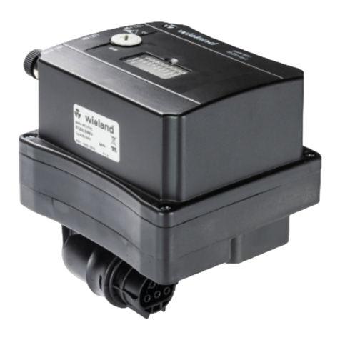
This instruction leaflet describes the assembly and connection of the gesis MSS
PAV 3I/W 1,5. Make sure to heed the warnings and adhere to the instructions. Für
commissioning, operation and maintenance please refer to following dokuments:
Operating manual gesis MSS PAV 3I/W 1,5 Doc.-Nr. BA000666
WARNING
•Electric installations, placing devices into operation and maintenance tasks may
only be carried out by qualified electricians with relevant training in accident
prevention and while adhering to applicable regulations.
•Protective measures and mechanisms must correspond
•to applicable regulations.
•Damaged products may neither be installed nor operated.
•The plug connectors may never be connected or removed under load.
•Before opening the device, it must be removed from the mains and the load.
B) Function description
The tree-phase electronic motor starter gesis MSS PAV 3I/W1,5 can be operated
either as direct or as reversing starter with loads up to 1.5 kW. By means of phase
angle control, gesis MSS reduces the switch-on voltage and subsequently increases
it to mains voltage. The starting current is monitored, thus it can be observed
whether the motor is running at nominal speed. In this case, relay contacts bridge
the semiconductor switches to reduce power dissipation. gesis MSS switches three-
phase motor loads and monitors the motor current. gesis MSS is an AS-i slave
which takes its supply voltage directly from the AS-i bus. The device includes an
electronic motor protection which can be parameterized via the AS-i bus. Up to
three sensors with M12 connectors can be connected.
C) Block diagram
ADDR Addressing jack X5 M12, A-coded
X1, X4 RST20i5, black X7, X8 M12, A-coded
UB Sensor Supply 20 ... 30VDC nc not connected
D) Dimensions (specifications in mm)
E) Assembly
NOTE
•The base must be even and capable of supporting the weight.
•For the mounting to the base, only the provided boreholes in the base plate of
the device may be used. Additional boreholes in other locations are not permis-
sible!
Screw the device to the supporting plate with two fastening screws M4. Use
washers.
F) Connection configuration
Three-phase connections
Input X1 (plug, black) Motor output X4 (jack, black)
NOTE
•L1 is bridged to T1 and not switched.
•Phases L2 and L3 are switched by relays/TRIACS as follows:
−clockwise sense of rotation: L2 to T2 and L3 to T3
−counterclockwise sense of rotation: L2 to T3 and L3 to T2
AS-Interface connection X5
Plug X5 Connection Meaning
1 AS-Interface +
3 AS-Interface −
Digital inputs X7, X8 (M12)
Pin Description X7/X8 Note
1 UB 24V sensor supply1
2 IN0/IN2 digital input
3 0V 0V sensor supply1
4 IN0/IN1 digital input
5 not assigned not assigned
12
3
4
5
1The supply UB for the digital inputs on X7 and X8 is
handled by the AS-Interface
NOTE
To be able to ensure compliance with protection type IP 65 all connections not
being used must be fitted with protective caps!
G) Display elements
The status LEDs inform you about the actual state of the motor starter. See also
chapter 8 („Operation“) of the operating manual.
Nr. Color Name Note I/O bit
1 red Error
2 yellow Overload
3 yellow Fault
4 yellow M rev Motor
counterclockwise
5 yellow M fwd Motor clockwise
6 yellow IN2 Input IN2
7 yellow IN1 Input IN1
8 yellow IN0 Input IN0
9 red AS-i Fault
10 green AS-i Power AS-i voltage ok.
The operating condition of the AS-Interface is indicated as follows:
LED „AS-i
power“ (green)
LED „AS-i
fault“ (red)
Meaning
no supply voltage
normal operation
no data exchange (e.g. slave address 0)
• periphery fault (e.g. AS-i supply overload on
initiator inputs)
= off; = on;• = flashing (frequency 2 Hz)

Doc. # BA000687 - 11/2010 (Rev. B)
H) Technical data
Entire device
Input voltage 400 V ±10 % AC 3-phase
Line frequency 50 Hz ±10%
Operating current per phase 4 A
Energy supply connection RST20i5 jack, 5-pole (black)
Device protection external; motor starter is to be secured on
the input side with
20 A conductor protection
Diagnostics "Status" AS-i inputs, motor status
Diagnostics "Error message" Bus error, motor failure, overload, over
current, undercurrent
Motor plug outlet
Output voltage 400 V ±10 % AC 3-phase, 50 Hz ±10%
Nominal power min./max. 0.09 / 1.5 kW
Load current min./max. 0.2 A / 4.0 A
Motor connection with 5-pin (black) RST20i5 plug
Switching component Electronic power switch
Switching frequency Max. 1,000 switches per hr.
(load-dependant)
Switching times Type 10 ms
Operating mode DB (EN 60149-1-1 und 1-3), S3 max.
runtime 10 minutes
Utilisation category AC-3; squirrel cage motors: Starting,
switching off during operation
Overload protection Current monitoring
Isolation Safe separation of load circuit to the AS-i
circuit
Protection criteria Overload function (configuration via
parameter download)
Activation characteristics Class 10 approached (parameterisable)
Conductor and overload
protection
Short circuit withstand capability Not short circuit-proof
Device protection not included in the device
Conductor and short circuit protection
of supply line
20 A
Motor protection Internal
AS Interface
Field bus communication AS-i specification V3.0 profile 7.4
(IO=7; ID=4; ID1=F;ID2=0)
Field bus connection (AS-i) with circular plug-in connector M12
Electronic/control motor switch power
supply
from AS interface 60 mA
Current consumption from AS-i Max. 200 mA
Addressing Address 0 to 31 (A-Slave)
via M12-DC jack 1.3 mm
Digital inputs (via AS-i)
Number 3
Type Two- or three-wire initiators
Supply voltage AS-i 20…30 V DC
Input current Type 5 mA
Input resistance Type 5 kΩ
Power supply current per initiator Max. 40 mA ; if all three Initiators
are connected, the sum is 120 mA
Sampling time Approx. 5 ms
Connector sensors with circular plug-in connector M12
General data
Ambient temperature -20…+40 °C (above 40 °C derating)
Degree of protection IP 65
Relative humidity 10…95 %, no condensation
Operating level ≤1000 m
Chemical composition Halogen-free, LBS-free, RoHS conformed
Mounting Wall installation
Orientation optional, preferably vertical
Error confirmation/reset Automatic error reset via process image
Approval AS-i
Noise immunity meets EN 61800-3
Noise emission meets EN 61800-3 as well as limit value
class A according to EN 55011 and EN
55014
Climate class 3 K3
Type of cooling Self-cooling
I) Ordering information
Accessories
Energy bus cable (jack–plug)
(xx=cable length)
96.453.xx80.1
Motor connection cable (plug–free end)
(xx=cable length)
96.453.xx84.1
AS-i Handheld PPG 1 83.209.2204.1
AS-i programming cable 1.5 m 83.209.2205.0
Appendix: Process image (cyclical data exchange)
Process outputs Function
BIT 3 BIT 2 BIT 1 BIT 0
0 0 0 0 Motor stop
0 0 1 0 Enable clockwise (*) motor stop
0 0 1 1 Motor clockwise
0 1 0 0 Enable counterclockwise (*) Motor
stop
0 1 0 1 Motor counterclockwise
1 0 0 0 Acknowledgement (with start error
and after end „write parameter
string“)
x x x x reserved, motor stop
(*) The direction is enabled without delay (pause on reverse) and thus, a higher
switching frequency is made possible with this function.
In cyclical slave-master mode, the state of three sensor inputs and a „Ready for
operation“ message from the drive were reported according to the binary table of
the AS-i input bits:
Process inputs Function
BIT 0 X7 / „1“=24 V
BIT 1 X8 / „1“=24 V
BIT 2 X8 / „1“=24 V
BIT 3 „1“= starter ready (no starter error)
J) Status LED error diagnostics
Fault
Cause
Error Over-
load
Fault M rev M fwd
Current in right rotation > In
−Motor load too high
−Parameter: wrong motor current value
x x
Current in left rotation > In
−Motor load too high
−Parameter: wrong motor current value
x x
Overload switch-off
−Motor load too high
−Parameter: wrong motor protection
value
x flashes flashes
Motor current undercut or motor current
asymmetry switch-off
−Motor supply line interrupted
−Parameter: wrong minimum current
value
−Parameter: wrong asymmetry value
x x flashes flashes
No rotating field detected
−Wrong phase connection
−Motor not connected
x flashes flashes
Excess temperature switch-off
−Temperature inside housing too high
flashes flashes
Invalid parameter set transmitted
−Valid parameters transmitted to soft
starter
flashes flashes
Spin-up or spin-down time counterclock-
wise
flashes
Spin-up or spin-down time clockwise flashes
Flash error
−No access to flash memory
x x x flashes flashes
This manual suits for next models
1
Other Wieland Controllers manuals
Popular Controllers manuals by other brands
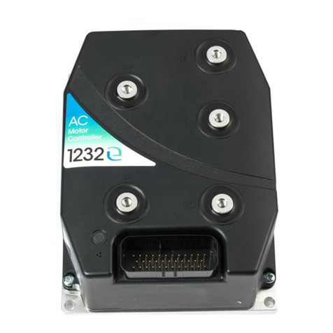
Curtis
Curtis 1232E manual
Hewlett Packard Enterprise
Hewlett Packard Enterprise Aruba 7240-US Product End-of-Life Disassembly Instructions
Fisher
Fisher R622 instruction manual
AAON
AAON ASM02655 Technical guide
Panasonic
Panasonic EYFRZ01 operating instructions
Victor
Victor EDGE ESS3 PARTS, SERVICE & REPAIR BULLETIN
LEUCHTWURM
LEUCHTWURM 43LED/528-W manual
CS Technologies
CS Technologies ACE-CONVERTER installation guide
Sensibo
Sensibo Sky installation manual

Wilo
Wilo CONTROL BOX CE+ WeH Installation and operating instructions
Eaton
Eaton xComfort CSAU-01/01 Instruction leaflet
Kutzner + Weber
Kutzner + Weber H100 installation instructions
