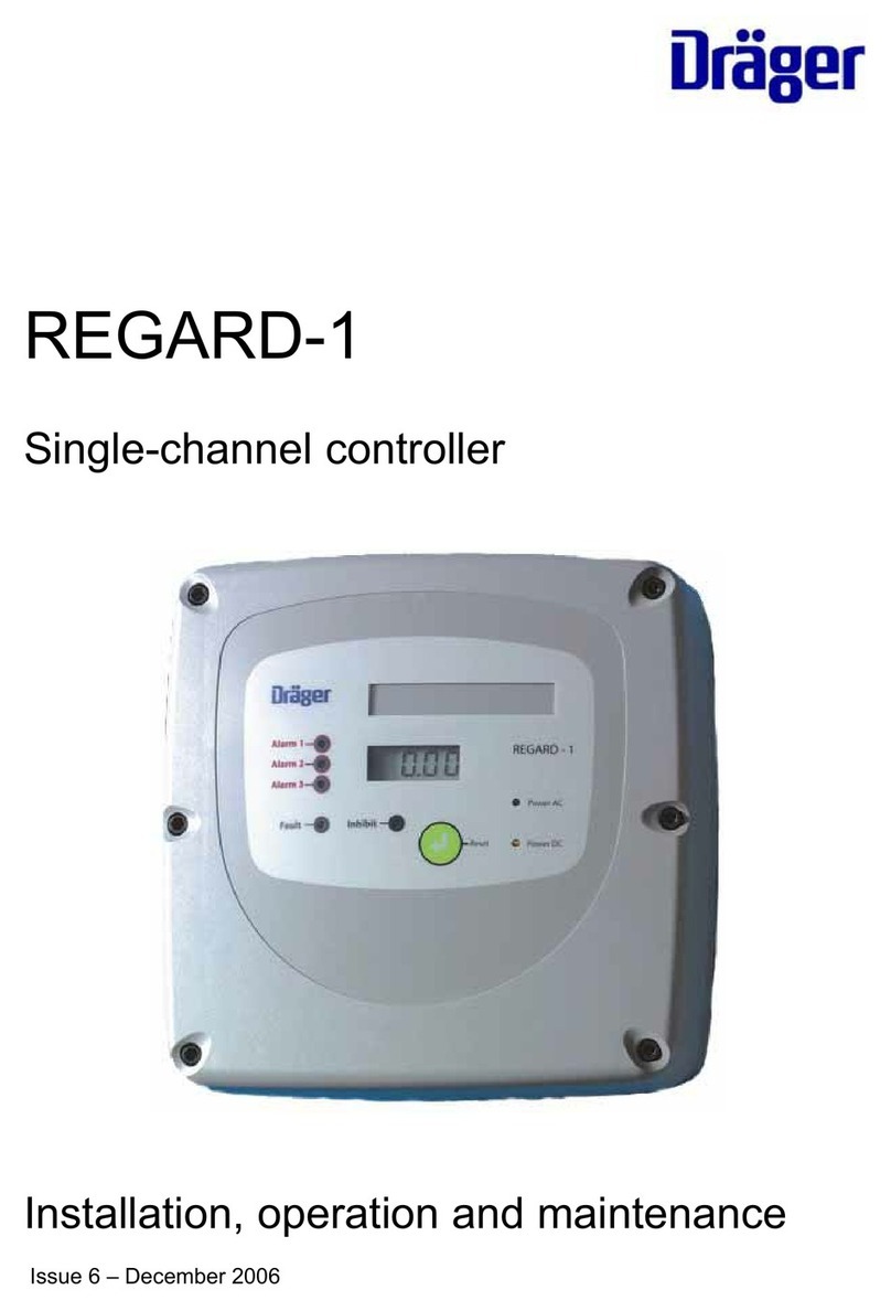
Dräger REGARD-1 User manual

Dräger. Technology for Life®
Regard-1 Single Channel Controller
Instructions for Use
i
WARNING
Strictly follow the Instructions for use. The user must
fully understand and strictly observe the instructions.
Use the equipment only for the purposes specied in this
document.
!


3
Regard-1 Single Channel Controller
Contents
Contents
1 For your safety .........................................................4
1.1 General safety statements .........................................4
1.2 Denitions of alert icons.............................................4
2 Description ...............................................................5
2.1 Product overview .......................................................5
2.2 Intended use ..............................................................5
2.3 Limitations on use ......................................................5
2.4 Approvals ...................................................................5
3 User information ......................................................6
3.1 Regard-1 controller overview .....................................6
3.2 Alarms and LEDs .......................................................6
3.3 Display .......................................................................6
3.4 Power LEDs ...............................................................7
3.5 Reset button (and remote reset) ................................7
4 Technical description ..............................................8
4.1 Main board .................................................................8
4.2 Display board .............................................................9
4.3 Pellistor board ............................................................9
4.4 Options board ............................................................9
5 Installation ..............................................................11
5.1 General instructions .................................................11
5.2 Positioning the controller..........................................11
5.3 Controller set up.......................................................12
5.4 Power supplies.........................................................13
5.5 Connecting transmitters and sensors ......................14
5.6 Other inputs and outputs..........................................17
6 Congurationandcalibration...............................20
6.1 Setting the measuring range and TWA function.......20
6.2 Calibrating the Regard-1 controller ..........................21
6.3 Setting the alarm operating modes ..........................23
6.4 Setting the alarm thresholds ....................................24
7 Troubleshooting.....................................................26
8 Maintenance ...........................................................27
9 Disposal ..................................................................27
9.1 Disposal of electrical and electronic equipment.......27
9.2 Batteries...................................................................27
10 Technical data ........................................................28
11 Order list .................................................................29
AnnexeA–Frontpanellabels ..........................................31

4Regard-1 Single Channel Controller
1 For your safety
1.1 General safety statements
● Before using this product, carefully read the Instructions
for Use.
● Do not dispose of the Instructions for Use. Ensure that they
are retained and appropriately used by the product user.
● Only fully trained and competent users are permitted to
use this product.
● Comply with all local and national rules and regulations
associated with this product.
● Only trained and competent personnel are permitted to
inspect, repair and service the product. Dräger recommends
a Dräger service contract for all maintenance activities and
that all repairs are carried out by Dräger.
● Properly trained service personnel must inspect and
service this product as detailed in the Maintenance section
of this document.
● Use only genuine Dräger spare parts and accessories, or
the proper functioning of the product may be impaired.
● Do not use a faulty or incomplete product, and do not
modify the product.
● Notify Dräger in the event of any component fault or
failure.
1.2 Denitionsofalerticons
Alert icons are used in this document to provide and highlight
text that requires a greater awareness by the user. A denition
of the meaning of each icon is as follows:
WARNING
Indicates a potentially hazardous situation which, if not
avoided, could result in death or serious injury.
CAUTION
Indicates a potentially hazardous situation which, if not
avoided, could result in physical injury or damage to
the product or environment. It may also be used to alert
against unsafe practices.
NOTICE
Indicates additional information on how to use the
product.
!
!
i
i
For your safety

5
Regard-1 Single Channel Controller
2.4 Approvals
2.4.1 CE marking and ATEX approval
Regard-1 is CE marked to indicate conformity to the following
directives:
● ATEX directive 94/9/EC.
● EMC directive 2004/108/EC.
● Low-voltage directive 2006/95/EC.
The controller also carries the following ATEX marking:
II (2) G
WARNING
THIS MARKING DOES NOT MEAN THAT THE UNIT
IS “EXPLOSION PROOF”. Regard-1 cannot be used in
areas subject to explosion hazards (“hazardous areas”)
without suitable protection.
Display board V2 and the options board are not in the scope of
the ATEX EC-type examination.
2.4.2 Other tests and approvals
In addition to the measuring function for ammable gases in
the range 0 to 100%LEL and for oxygen (inertization) in the
range 0 to 25%(V/V), Regard-1 has been tested according
to DIN EN 45544-1 combined with DIN EN 45544-2 for toxic
gases, and according to DIN EN 50104 for oxygen enrichment
and oxygen deciency, by DEKRA EXAM GmbH, Bochum,
Germany.
In Germany only:
The “Bericht über die Eignungsuntersuchung” has been issued
under PFG-No. 41301303. Read and consider Chapter 5 of
the “Bericht über die Eignungsuntersuchung” (which follows in
German language version of the manual only).
2.4.3 Special conditions for safe use according to EC-
typeexaminationcerticateBVS03ATEXG011X
Vibration can cause malfunction of alarm and fault contacts.
Do not expose to vibrations with frequencies above 55 Hz or
amplitudes above 0.15 mm.
For safety relevant decisions, only use the status of the
relays. Do not use the display reading or LED indications. For
calibration and adjustment of alarm set points use a voltmeter
between test points TP1 and TP2 to determine the gas reading
and the alarm thresholds.
Do not set an alarm threshold below 0% or above 100% of the
measuring range.
For Regard-1 SE Ex, verify that the gas concentration at the
sensor is below full scale before resetting latched alarms.
If the control unit Regard-1 4-20 is operated with a remote
sensor for ammable gases whose output current can be
below 20 mA for concentrations above full scale, verify that
the gas concentration at the sensor is below full scale before
resetting latched alarms.
!
Description
2 Description
2.1 Product overview
The Regard-1 is a single channel controller that is used with a
gas detector to provide stationary, continuous monitoring and
warning of potentially dangerous or harmful conditions. The
controller is available in two main variants: Regard-1 4–20 mA
for use with a 4–20 mA transmitter; or Regard-1 SE Ex for use
with an SE Ex sensor. The internal components and settings
differ for each of the variants, and additional functionality can
be enabled by installing optional components or conguring
the controller settings.
More detailed descriptions of the controller and the available
functions are shown in the user information (see Section 3 on
Page 6).Additional information for installation and maintenance
technicians is shown in the technical description (see Section 4
on Page 8).
2.2 Intended use
The Regard-1 single-channel controller is suitable for use
in residential, commercial and industrial environments to
provide:
● Display of measured gas level.
● Visual and audible alarms at the controller and alarm
outputs to external warning devices.
● TWA (time-weighted average) output and a datalog of
controller events (only available on controllers tted with
an options board).
The controller can be used with a 4–20 mA transmitter or an
SE Ex sensor to provide the following functions:
● Regard-1 4–20 mA: For stationary, continuous monitoring
of ammable or toxic gases and vapours, and oxygen
deciency or enrichment.
● Regard-1 SE Ex: For stationary, continuous monitoring of
ammable gases and vapours.
The Regard-1 controller is certied according to the directive
94/9/EC (ATEX Directive) to be operated with performance
approved 4–20 mA transmitters (EC-type examination
certicate BVS 03 ATEX G 011X), or with Dräger sensing
heads SE Ex PR M, SE Ex PR M* DD or SE Ex HT M DD.
2.3 Limitations on use
WARNING
Do not use the Regard-1 controller in areas subject to
explosion hazards (“hazardous areas”) without suitable
protection. Contact Dräger for further information.
The Regard-1 controller cannot be used with the following
detector types:
● Dräger SE Ex LC sensor.
● Three-wire transmitter that has a 4–20 mA sink output.
!

6Regard-1 Single Channel Controller
The inhibit LED only illuminates during maintenance or repair
of the controller. When illuminated, the LED indicates that the
controller internal relays are forced to the non-alarm or non-
fault state.
3.2.1 Internalbuzzer
A buzzer inside the controller provides an audible alarm when
any alarm or fault activates, and during the controller start-up
sequence.
3.3 Display
When tted, the display normally shows the gas level, but
it also indicates a number of other warning or information
messages.
Normal gas level reading.
Negative gas level reading – A negative reading may
occur due to drift or temperature effect. If a negative
reading appears frequently or for long periods, refer
to the troubleshooting information (see Section 7 on
Page 26).
Under range – The gas level is below the measuring
range. Refer to the troubleshooting information (see
Section 7 on Page 26).
Over range – The gas level exceeds the measuring
range. The over range indication is latching and
can only be cleared when the gas level is within the
measuring range. Press the reset button to clear an
over range indication.
TWA reset to zero.
3.3.1 Self test
Each time that the controller is connected to a power supply or
switched on, it performs a self test and then enters the active
mode. The self test sequence is shown below.
Start of self test.
Display board rmware version (rmware versions
available: r1.00, r1.01, r2.00 and r 2.01).
Start of countdown.
End of countdown.
At the end of the self test, the display shows the gas level and
the internal buzzer sounds. Press the reset button to silence
the buzzer.
If the controller fails the self test, or if the display board
watchdog detects a fault condition, the countdown will cycle
on the display screen. Refer to the troubleshooting table for
possible reasons (see Section 7 on Page 26).
0.50
-0.5
-Ur-
-Or-
tA-0
Test
r1.00
9999
. . . .
3 User information
3.1 Regard-1 controller overview
3.2 Alarms and LEDs
WARNING
The alarm levels and the activation modes are congured
to meet the requirements of the user. Therefore, the
actions and countermeasures which are to be taken
when any gas or fault alarm activates must be dened
by the person responsible for the gas detection system.
When an alarm condition occurs, it activates an alarm relay
inside the controller, illuminates the relevant LED and triggers
the internal buzzer. The internal relays are connected to the
external warning devices selected by the person responsible
for the gas detection system. The external warning devices
provide the main indication of alarm activation.
The controller provides up to three detection alarm levels (A1
to A3) and a fault alarm. Additionally the controller can provide
a TWA (time-weighted average) alarm facility if required. The
TWA is an average gas level calculated over a preset period.
Alarms can be latching or non-latching, and can be set to
activate when rising or falling.
● Latching alarms remain activated when the alarm condition
is no longer present.
● Non-latching alarms switch off when the alarm condition is
no longer present.
Additionally, the A2 alarm can be set to be acknowledgeable.
When the A2 alarm is set to be acknowledgeable, the alarm
device connected to the A2 alarm output can be switched off or
silenced when the alarm condition is still present.
!
User information
3426
1
3
5
2
4
1 Alarm, fault and inhibit LEDs (see Section 3.2).
2 Label window. Shows the measured gas, range, units and
alarm settings.
3 Display (optional) (see Section 3.3).
4 Power LEDs (see Section 3.4 on Page 7)
5 Reset button (see Section 3.5 on Page 7).

7
Regard-1 Single Channel Controller
3.4 Power LEDs
The power LEDs illuminate to indicate that power is supplied
to the controller:
● When DC is supplied, only the DC power LED illuminates.
● When AC is supplied, both LEDs illuminate (the DC power
LED illuminates to indicate that internal battery charging
supply is available).
When an AC supply is used, rechargeable batteries may be
tted to provide a backup in case of main supply failure. When
tted the rechargeable batteries provide continued operation
for several hours if AC power is interrupted.
3.5 Resetbutton(andremotereset)
The reset button is used to acknowledge or cancel alarms
and messages. When a remote reset switch is connected to
the controller, it performs the same functions remotely from the
controller.
Reset button (and remote reset switch if available) operation:
● Pressing and releasing the reset button:
○ Acknowledges or resets activated alarms.
○ Cancels other on-screen messages (for example: an
over range (-Or-) message).
● Pressing and holding the reset button for approximately
10 seconds resets the TWA value to zero (display message:
tA-0) and restarts the TWA calculation period.
User information

8Regard-1 Single Channel Controller
Technical description
4 Technical description
4.1 Mainboard
1 24 V Battery terminals (see Section 4.1.4 on Page 9).
2 Fuses (see Section 4.1.3 on Page 9).
3 Input and output terminals (see Section 4.1.1 on Page 8).
4 Maintenance inhibit jumper socket (see Section 4.1.2 on
Page 9).
Further explanation of the main board components and
connectors is provided in the installation and calibration
information later in the document.
4.1.1 Input and output terminals
3427
Terminal Function
1 2
Reset
Remote reset input
3 4
- 20 mA +
4–20 mA output (requires options board)
5 6
- 24 V +
24 Vdc unswitched output (100 mA max.)
7 8 9
- Input +
4–20 mA transmitter or SE Ex sensor input
10- 11+
12- 13+
A1 24 V switched output (100 mA max.)
A2 24 V switched output (100 mA max.)
14 15 16
17 18 19
A1 relay output
A2 relay output
20 21 22
23 24 25
TWA relay output (requires options board)
A3 relay output
26 27 28
29 30 31
Fault relay output
Inhibit relay output
N E L 98 to 253 Vac fused output (500 mA max.) (back row terminals)
98 to 253 Vac input (front row terminals)
3427
1
2
4 3

9
Regard-1 Single Channel Controller
4.2 Displayboard
A display board is an optional component which, when tted,
provides the display. There are two versions of the display
board available:
● V1 – Contains rmware version r1.00 or r1.01. Calculates
a TWA gas level over eight hours.
● V2 – Contains rmware version r2.00 or r2.01. Calculates
the TWA gas level over a user adjustable period.
4.3 Pellistorboard
A pellistor board is used with SE Ex sensors to supply a
constant current to the sensor, and amplify the signal from
the sensor. The pellistor board has a 4-pole switch and three
potentiometers that are used during the calibration of an SE Ex
controller (see Section 6.2.2 on Page 22).
4.4 Optionsboard
An options board is an optional component which, when tted
to the controller, provides:
● A TWA alarm relay (requires display board V2 to operate).
● A 4–20 mA output proportional to gas level (on terminals 3
and 4 of the main board).
● A datalog output with RS-232 communication.
4.4.1 TWA(time-weightedaverage)
The TWA is an average gas level calculated over a dened
period:
● For rmware version r1.00 or r1.01, TWA is calculated over
the previous eight hour period.
● For rmware version r2.00 or r2.01, TWA is calculated over
a user adjustable period. The default setting is eight hours
but it can be adjusted to a user dened period.
Connecting or switching on the controller, or resetting the
TWA (see Section 3.5 on Page 7), starts the TWA gas level
calculation. The TWA value is not available until the initial
calculation period (eight hours or other user dened period)
has elapsed. Once the initial period has elapsed the TWA gas
level is constantly updated.
● The TWA gas level is recorded in the datalog.
● When the controller is tted with a V2 display board, the TWA
gas level can be used to activate the TWA alarm relay.
NOTICE
The rmware version is shown on the display for a few
seconds when the controller is connected or switched on.
To adjust the TWA calculation period or to set the
TWA alarm relay requires additional software which is
available from Dräger. Contact Dräger for details.
i
i
Technical description
4.1.2 Maintenanceinhibitjumpersocket
A jumper is tted to the JP1 terminals on the main board to
inhibit alarms and fault signals during testing or calibration.
When an inhibit jumper is tted all relays will be held in their
normal (non-alarm or non-fault) state.
4.1.3 Fuses
Fuse F5 – AC output fuse (500 mA)
Fuse F6 – AC input fuse (500 mA)
4.1.4 24VBatteryterminals
The 24 V battery terminals are for connection of an external
DC supply (18 to 30 Vdc), or for rechargeable batteries as a
backup supply when an AC supply is used for the controller. Full
details are in the power supplies information (see Section 5.4
on Page 13).
3434
Maintenanceinhibitjumpersocket
3429
Fuse F5
Fuse F6
3430

10 Regard-1 Single Channel Controller
3432
RJ11 socket
4.4.2 Datalog
When the controller is tted with an options board, the system
records a datalog of events which can be viewed on a PC.
The datalog output uses RS-232 communication to output
the datalog on an RJ11-style socket on the options board. A
PC connection lead is available from Dräger (see Section 11
on Page 29) and details of the lead are shown in the table
below.
Technical description
RJ11 socket RS232SubD–9Pole
Pin Function Pin Function
1 Rx 3 Tx
2 0 V 5 GND
3 Tx 2 Rx
4 0 V 5 GND
1 nc
6 nc
7RTS
8 CTS
9 nc
NOTICE
To view the datalog or change the datalog settings
requiresaPC utility(for example:MicrosoftHyperTerminal
or HyperACCESS by Hilgraeve). Contact Dräger for
details.
When connected to a PC, data is sent by the controller as
ASCII characters (see Section 10 on Page 28 for the datalog
specication). Additionally, the gas level and TWA are printed
on screen every second in the following format:
Gas 20.1 TWA 0.1
i
i

11
Regard-1 Single Channel Controller
5 Installation
WARNING
This section and all subsequent sections contain
technical and set-up information for trained maintenance
technicians. The procedures should not be attempted
by untrained personnel as it could make the controller
or gas detection system unsafe for use.
Refer also to the transmitter or sensor instruction manual for
information about the transmitter or sensor.
The conguration settings can be altered and internal control
boards can be removed or installed in order to set up the
controller to meet the gas detection and warning requirements.
The Regard-1 controller is supplied congured for use with a
4–20 mA transmitter or an SE Ex sensor but can be adapted
to be used with the other detector type.
5.1 General instructions
The following general instructions should be used for all
installation tasks described in this section:
WARNING
Disconnect or switch off all AC and DC supplies to
the controller before attempting any of the component
installation/removal tasks or any wiring connection or
disconnection. Failure to disconnect the power supply
may result in personal injury and/or may damage the
controller, detector, or wiring.
1. Release the six cover screws and remove the cover.
2. Disconnect or switch off all AC and DC supplies to the
controller.
3. Carry out the necessary wiring and installation/removal
tasks as described in this section.
!
!
Installation
4. Recongure and calibrate the controller as necessary (see
Section 6 on Page 20).
5. Check the sealing ring and ret the controller cover. Tighten
the six cover screws.
5.1.1 Cableentries
CAUTION
Do not attempt to knock out the cable entries as it may
crack the casing.
1. Use an M20 hole cutter to cut out the adjacent pre-marked
cable hole on the bottom of the box casing.
2. Insert the cable and t an M20 cable gland to seal the
opening and prevent moisture ingress.
5.2 Positioning the controller
WARNING
The Regard-1 controller is not “explosion proof” and
must not be installed in a hazardous area without
additional Ex-protection.
Select the installation position observing the following:
● Locate the controller where it is accessible and the display
and indicators are easily seen.
● Temperature and humidity conditions: 0 °C to 55 °C; 0 to
100% rH, non-condensing.
● Avoid locations where excessive vibration (frequency
above 55 Hz or amplitude above 0.15 mm) is possible.
● Avoid locations where aggressive or corrosive gases,
contaminants or pollutants harmful to electronic equipment
are present.
!
!
114 114
185
3436
Mountingtemplate(dimensionsnottoscale)

12 Regard-1 Single Channel Controller
Rechargeablebatteries Displayboard
Pellistorboard Optionsboard
3433
Installation
5.3 Controller set up
5.3.1 Fittingorremovingcontrolboards
Fittingorremovingadisplayboard
To t a display board:
1. Connect the display board socket to SK3 on the main
board.
2. Position the display board and t the three screws to
secure.
Removing the display board is the reverse procedure.
Fittingorremovingapellistorboard
To t a pellistor board:
1. Remove the links tted at positions A–E on SK2 on the
main board (retain the links).
2. Fit the pellistor board on to SK2.
If the pellistor board is removed, ensure that the links are
retted to position A–E on SK2.
Fittingorremovinganoptionsboard
To t an options board:
1. Remove the two screws and move the display board to
one side. Do not disconnect the board connector.
2. Fit the options board on to SK6 and SK9 on the main
board.
3. Reposition the display board and t the two screws to
secure.
Removing the options board is the reverse procedure.
Fittingorremovingrechargeablebatteries
The specications for rechargeable batteries are shown in
the backup power supply information (see Section 5.4.2 on
Page 13).

13
Regard-1 Single Channel Controller
5.3.2 Display of measuring range, gas and unit
Insert a label into the slot inside the front cover above the
display to show the detection and alarm settings. Pre-printed
labels are in Annexe A on Page 31.
5.3.3 Adjustingthedisplayscreencontrast
1. Connect a power supply to the controller (see Section 5.4
on Page 13).
2. Adjust the contrast potentiometer on the display board to
lighten or darken the display characters.
Installation
5.4 Power supplies
5.4.1 Main power supply
CAUTION
Do not connect an AC supply and an external DC supply
at the same time as it may damage the controller.
NOTICE
If an AC supply is from an AC socket, the maximum
length of cable between the socket and the controller is
3 m.
Connect an external AC supply (98 to 253 Vac) to the input
(NEL) front row terminals or connect an external DC supply
(18 to 30 Vdc) to the 24 V battery terminals.
!
i
i
5.4.2 Backuppowersupply
CAUTION
Dräger recommend using only sealed batteries inside
the controller as unsealed batteries can release
hydrogen during charging. If unsealed batteries are
used, drill a vent hole in the top of the enclosure and
t a suitable breather valve that prevents moisture
ingress.
When using an AC supply, rechargeable batteries can be tted
to provide a backup supply when the AC supply fails.
● If required, connect two 12 V 1.2 Ah rechargeable batteries
in series to the 24 V battery terminals (see Section 11 on
Page 29 for Dräger supply).
● The battery charging supply is: 27.6 ± 0.6 Vdc at 500 mA
max.
● The batteries provide continued operation for several hours
if AC power is interrupted.
!
3437
3434
Contrast potentiometer
3435

14 Regard-1 Single Channel Controller
Installation
5.5 Connecting transmitters and sensors
5.5.1 Two-wire 4–20 mA transmitter
● Use cable with braided copper screen.
5.5.2 Three-wire 4–20 mA transmitter
● Only connect a transmitter that has a 4–20 mA source output.
Regard-1 cannot be used with a three-wire transmitter that
has a 4–20 mA sink output.
● Use cable with braided copper screen.
● Use a cable where the three cores each have the same
resistance.
● To ensure that a short circuit between the 4–20 mA output
and the zero volt wire at the transmitter causes a fault
indication at the controller, each cable core must not exceed
the resistance given by the formula: Rcable = 800/Itxr.
Main board
7 8 9
0 V
4-20 mA signal
+24 V
4-20 mA transmitter
3423
Main board
7 8 9
4-20 mA signal
+24 V
4-20 mA transmitter
3420
Rcable = 800/Itxr:: Rcable is the maximum resistance per core from
Regard-1 to the transmitter.
Itxr is the transmitter operating current (in mA).
Example: Using a transmitter with an operating current
of 200 mA, Rcable = 800/200 = 4 Ω per core).

15
Regard-1 Single Channel Controller
Installation
5.5.3 Two-wire4–20mAtransmitterwithsafetybarrier
● Refer also to the instructions for the safety barrier and
transmitter for connections between transmitter and barrier,
and for the barrier earth connection.
● Use cable with braided copper screen.
Main board
5 6 7 8
Transmitter
+24 V
Signal
Ex i
Safety barrier
0 V
+24 V
0 V
Signal
Hazardous Area Non-Hazardous Area
3425

16 Regard-1 Single Channel Controller
Installation
5.5.4 Dräger(Polytron)SEExsensinghead
CAUTION
Disconnect or switch off all power supplies to the
controller before connecting a Dräger SE Ex sensor.
Connecting when the controller is powered will damage
the sensor.
● The Regard-1 controller cannot be used with Dräger
SE Ex LC sensor.
● Use cable with braided copper screen.
● The maximum cable resistance is 6 Ω per core. The table
below shows the maximum cable length according to the
cross-sectional area, using a typical connector cable.
Cablex-section Maximum length
1.0 mm2250 m
1.5 mm2400 m
2.5 mm2700 m
4.0 mm21000 m
!
Main board
7 8 9
Brown
Yellow
Black
SE Ex sensing head
3419

17
Regard-1 Single Channel Controller
5.6 Other inputs and outputs
5.6.1 Relay outputs
● Use screened or unscreened cable for relay outputs.
● The relay outputs are volt-free outputs that can be used for
external warning devices. The voltage and current ratings
of the relay contacts are shown in the technical data (see
Section 10 on Page 28).
● When an internal supply is required to drive the external
device, use the unswitched 24 Vdc output on terminals 5(-)
and 6(+) of the main board.
● The A1, A2, A3, TWA and inhibit relays energize on alarm
(normally de-energized). The fault relay de-energizes on
alarm (normally energized).
● The gures below show the relay contacts when relays are
in their normal (non-alarm or non-fault) state.
Installation
3438
Main board
A1 relay
14 15 16 17 18 19 20 21 22
Main board
23 24 25 26 27 28 29 30 31
A2 relay TWA relay
A3 relay Fault relay Inhibit relay

18 Regard-1 Single Channel Controller
5.6.2 A1andA224Vswitchedoutputs
● Use the switched outputs to drive external warning devices
directly (the examples below show a ashing beacon activated
by A1 and a klaxon activated by A2).
● Use cable with braided copper screen.
● The voltage output decreases as the current drawn
increases, as shown in the table below.
Output voltage Current drawn
22 V 30 mA
18 V 100 mA
A1 switched output
Installation
Main board
10 11
3424
Main board
12 13
3421
A2 switched output

19
Regard-1 Single Channel Controller
5.6.3 Remote reset input
● To acknowledge and reset alarms remotely from the
controller, connect a normally-open switch to the remote
reset terminals.
● Use cable with braided copper screen.
Installation
5.6.4 4–20 mA proportional output
● Use the 4–20 mA proportional output (only available when
an options board is tted) to deliver the gas level signal to
an external device.
● Use cable with braided copper screen.
Main board
1 2
3422
Main board
3 4
4-20 mA
External device
3444
Transmitters and sensors
For installation and maintenance instructions of the transmitter
or sensor that is connected to the controller refer to the relevant
transmitter/sensor instruction manual.

20 Regard-1 Single Channel Controller
6 Congurationandcalibration
If it is necessary to inhibit alarms and fault signals during
testing or calibration, t the maintenance inhibit jumper to
the JP1 terminals on the main board (see Section 4.1.2 on
Page 9).
WARNING
Fitting the jumper holds all relays in their normal (non-
alarm or non-fault) state. Always remove the jumper
before returning the controller to normal monitoring
operation.
6.1 Setting the measuring range and TWA
function
● Use switch SW1-A to E on the display board to set the
display measuring range.
● Refer to the relevant table depending on the rmware
version of the controller (the rmware version is shown on
the display briey during the self-check when the controller
is connected or switched on).
● The number of decimal places (DPs) shown depends on
the measuring range.
!
Conguration and calibration
r1.01orr2.01rmware
Measuring
range
DPs SW1
ABC D E
0–1 2 OFF OFF OFF OFF OFF
0–3 2 ON OFF OFF OFF OFF
0–5 2 OFF ON OFF OFF OFF
0–8 2 ON ON OFF OFF OFF
0–10 2 OFF OFF ON OFF OFF
0–20 1 ON OFF ON OFF OFF
0–25 1 OFF ON ON OFF OFF
0–30 1 ON ON ON OFF OFF
0–50 1 OFF OFF OFF ON OFF
0–100 1 ON OFF OFF ON OFF
0–200 0 OFF ON OFF ON OFF
0–250 0 ON ON OFF ON OFF
0–300 0 OFF OFF ON ON OFF
0–500 0 ON OFF ON ON OFF
0–1000 0 OFF ON ON ON OFF
0–2000 0 ON ON ON ON OFF
0–2500 0 OFF OFF OFF OFF ON
0–3000 0 ON OFF OFF OFF ON
0–5000 0 OFF ON OFF OFF ON
0–9999 0 ON ON OFF OFF ON
● Use switch SW1-F on the display board to set the TWA
function (for all rmware versions).
SW1-F TWA
ON ON
OFF OFF
3439
SW1
r1.00orr2.00rmware
Measuring
range
DPs SW1
ABC D E
0–1 2 OFF OFF OFF OFF OFF
0–3 2 ON OFF OFF OFF OFF
0–5 2 OFF ON OFF OFF OFF
0–10 2 ON ON OFF OFF OFF
0–25 1 OFF OFF ON OFF OFF
0–30 1 ON OFF ON OFF OFF
0–50 1 OFF ON ON OFF OFF
0–100 1 ON ON ON OFF OFF
0–200 0 OFF OFF OFF ON OFF
0–250 0 ON OFF OFF ON OFF
0–300 0 OFF ON OFF ON OFF
0–500 0 ON ON OFF ON OFF
0–1000 0 OFF OFF ON ON OFF
0–2000 0 ON OFF ON ON OFF
0–2500 0 OFF ON ON ON OFF
0–3000 0 ON ON ON ON OFF
0–5000 0 OFF OFF OFF OFF ON
0–9999 0 ON OFF OFF OFF ON
Other manuals for REGARD-1
2
Table of contents
Other Dräger Controllers manuals
Popular Controllers manuals by other brands

All Motion
All Motion EZStepper EZ4AXIS quick guide

Texas Instruments
Texas Instruments TMS320DM644x user guide

Siemens
Siemens SQL36E65 Mounting instructions

Bosch
Bosch Junkers TR 100 manual

EUCHIPS
EUCHIPS DMX-E05 manual

Hughes Network Systems
Hughes Network Systems GMH2000 Installation and maintenance manual