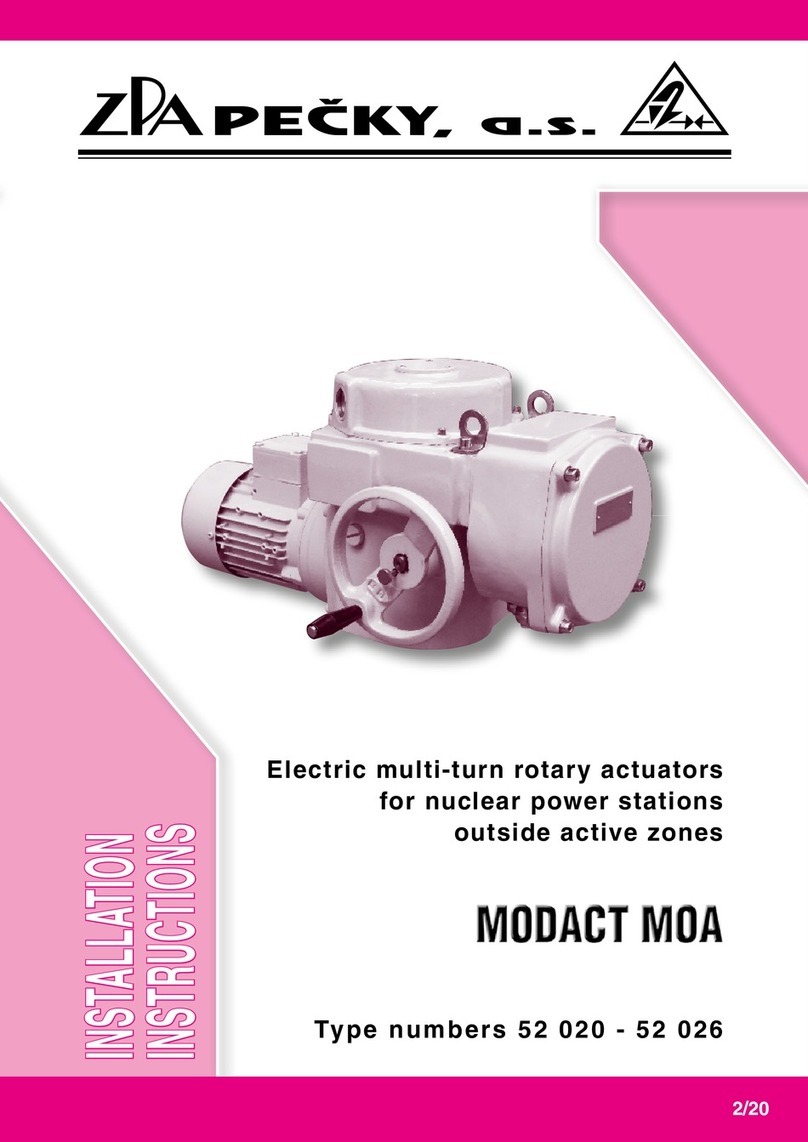
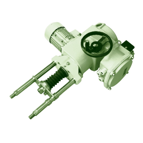
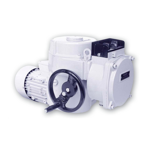
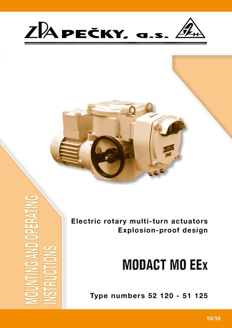
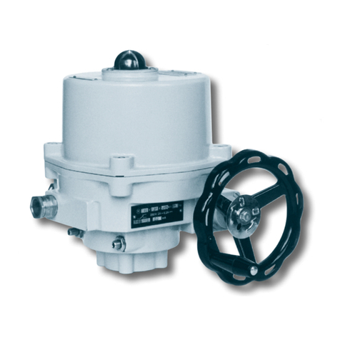
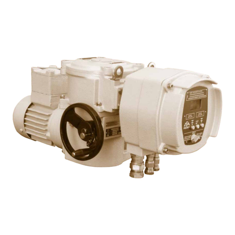
ZPA Pecky, a.s. MODACT MOK 125 User manual

Type Numbers 52 325 - 52 329
Electric Part-turn (90°) Actuators
for Ball and Flap Valves
10/18
MODACT MOK 63 t.n. 52 325
MOK 125 t.n. 52 326
MOK 250 t.n. 52 327
MOK 500 t.n. 52 328
MOK 1000 t.n. 52 329
MODACT MOK CONTROL
MOK 1000 t.n. 52 329
MODACT MOK CONTROL
MODACT MOK CONTROL
INSTALLATION AND OPERATING
INSTRUCTIONS

ZPA Pečky, a.s. is certified company in accordance with ISO 90001 as amended.

3
1. APPLICATION
The actuators MODACT MOK are designed for shifting control elements by a reversible rotary motion with
the turning angle of the output part 90°, including cases when tight closure in end positions is required. Typical
example of using is control of ball and flap valves in similar installations in the regime of remote control as well
as automatic regulation. The electric actuators MODACT MOK are mounted directly on the controlled element.
2. OPERATING CONDITIONS, OPERATING POSITION
Operating conditions
The actuators MODACT MOK (MODACT MOK Control) are resistant against effect of operating conditions
and external effects of classes AC1, AD5, AD7, AE5, AE6, AF2, AG2, AH2, AK2, AL2, AM-2-2, AN2, AP3, BA4
and BC3 according to ČSN 33 2000-5-51 ed. 3.
When the actuator is installed on a free area it is recommended to fit it with a light shelter against direct impact
of atmospheric effects. The shelter should overlap the actuator contour by at least 10 cm at the height of 20 – 30 cm.
When actuators are to be installed in the working environment with temperature below +10 °C and in the environment
with relative humidity above 80 %, it is always necessary to use an anti-condensation heater fitted to the actuator.
The electric actuators can be installed in areas with non-flammable and non-conductive dust, provided that this
does not adversely influence their function. Here, it is necessary to strictly observe ČSN 34 3205. It is recommended to
remove dust as soon as its layer is about 1 mm thick.
Notes:
The area under a shelter means the one where falling of atmospheric precipitations under and angle up to 60° from
the vertical is prevented.
The electric actuator must be installed in a place where cooling air has a free access. Minimum distance from a wall for
access of air is 40 mm. Therefore, the area where the electric actuator is installed must be sufficiently large, clean and ventilated.
Surrounding temperature
Operating temperature for the MODACT MOK is from -25 °C to +70 °C or from -60 °C to +60 °C.
Classes of external effects – excerpt from ČSN 33 2000-5-51 ed. 3.
Class:
1) AC1 – elevation above sea level ≤ 2000 m
2) AD5 – spouting water; water can spout in any direction
AD7 –
shallow occurence – shallow dipping
3) AE5 – medium dustiness
AE6 – strong dustiness
CONTENS
1. Application .................................................................................................................... 3
2. Operating conditions; Operating position ..............................................................................3
3. Operation mode, Service life of actuators .............................................................................. 4
4. Technical data ................................................................................................................ 5
5. Actuator outfit ................................................................................................................6
6. Electric parameters ..........................................................................................................7
7. Technical description ....................................................................................................... 8
8. Adjustment of the actuator ................................................................................................. 9
9. Position regulator ZP2.RE version 4 ................................................................................... 12
10. Technical parameters of actuator ....................................................................................... 15
11. Installation and putting into operation ................................................................................ 18
12. Attendance and maintenance ........................................................................................... 19
Tables ..........................................................................................................................20–22
Dimensional sketch of electric actuators MOK ........................................................................22–25
Wiring diagrams ..............................................................................................................27–35
Spare parts......................................................................................................................... 36

4
4) AF2 – occurrence of corrosive or polluting substances from atmosphere. Presence of corrosive polluting
substances is significant.
5) AG2 – medium mechanical stress by impacts – common industrial processes
6) AH2 – medium mechanical stress by vibrations – common industrial processes
7) AK2 – serious risk of growth of vegetation and moulds
8) AL2 – serious danger of the occurance of animals (insects, birds, small animals)
9) AM-2-2 – normal level of the signal voltage. No additional requirements
10) AN2 – medium solar radiation with intensities > 500 W/m2 and ≤ 700 W/m2
11) AP3 – medium seismic effects; acceleration > 300 Gal ≤ 600 Gal
12) BA4 – personal abilities. Instructed people.
13) BC3 – frequent contact with the earth potential. Persons coming frequently into contact with "live" parts or
standing on a conducting base.
Operating position
The actuators can be used in any operating position.
3. OPERATION MODE, SERVICE LIFE OF ACTUATORS
Operation mode
The actuators can be operated with the type of loading S2 according to ČSN EN 60 034-1. The run period
at temperature +50 °C is 10 minutes; the mean value of loading torque should not exceed 60 % of the value of
maximum tripping torque Mv. The actuators can also work in the regime S4 (interrupted run with start-up) according to
ČSN EN 60 034-1. Load factor N/N+R is max. 25 %; the longest working cycle (N+R) is 10 minutes (course of working
cycle is shown in the figure). The highest number of closing operations in automatic regulation is 1200 cycles per hour.
Mean value of loading torque with load factor 25 % and surrounding temperature +50 °C is not higher than 40 %
of maximum tripping torque Mv.
The highest mean value of loading torque is equal to rated torque of the actuator.
Corrosion protection
Actuators are standardly delivered with surface treatment corresponding to category of corrosion aggressiveness
C1, C2 and C3 according to ČSN EN ISO 12944-2.
On customer's request is possible to do surface treatment correcponding to category of corrosion aggressiveness
C4, C5-I and C5-M.
In following table is provided and overview of environment for each categories of corrosion aggressiveness accor-
ding to ČSN EN ISO 12944-2.
Corrosion
aggressiveness
level
Example of typical environment
Outdoor Indoor
C1 Heated buildings with clean atmosphere
(very low) e.g. offices, shops, schools, hotels.
C2 Atmosphere with low level of pollution. Unheated buildings, in which may occur
(low) Mostly outdoor areas. condensation, e.g. stocks, sports halls.
C3 Urban industrial atmospheres, Production areas with high humidity and low air
(middle) mild pollution of sulfur dioxide. pollution, e.g. food industry, processing
Seaside areas with middle salinity. factories, breweries.
C4 Industrial areas and seaside areas Chemical plants, swimming pools,
(high) with middle salinity. seaside shipyard.
C5-I
(very high Industrial areas with high humidity Buildings or areas with predominantly continuous
– industrial) and aggressive atmosphere. condensation and high air pollution.
C5-M
(very high Seaside areas with high salinity. Buildings or areas with predominantly
– seaside) continuous condensation and high air pollution.

Service life of actuators
The actuator intended for shut-off valves must be able to perform at least 10,000 operating cycles (C - O - C).
The actuator intended for regulating purposes must be able to perform at least 1 million cycles with operation time (during
which the output shaft is moving) at least 250 hours. Service life in operating hours (h) depends on load and number
of switching. Not always, high frequency of switching influences positively accuracy of regulation. For attaining the longest
possible faultless period and service life, frequency of switching is recommended to be set to the lowest number of switching
necessary for the given process. Orientation data of service life derived from the set regulation parameters are shown in
the following table.
Service life of actuators for 1 million starts
Service life [h] 830 1 000 2 000 4 000
Number of starts [1/h] Max. number of starts 1200 1 000 500 250
4. TECHNICAL DATA
Supply voltage
Supply voltages of the actuators are shown in Table 1.
1 x 230 V, +10 %, -15 %, 50 Hz ±2 %
3 x 230/400 V, +10 %, -15 %, 50 Hz ±2 %
(or as shown on the motor rating plate)
Other supply voltage for electric actuators should be discussed with the manufacturer.
Protective enclosure
Protective enclosure of actuators MODACT MOK IP 67 according to ČSN EN 60529.
Noise
Level of acoustic pressure A max. 85 dB (A)
Level of acoustic output A max. 95 dB (A)
Tripping torque
At the factory, the tripping torque has been adjusted as shown in Table 1, according to the customer’s requirements.
If no tripping torque adjustment has been specified by the customer the maximum tripping torque is adjusted.
Self-locking
The actuators are self-locking. Self-locking facility of the actuators is provided by a mechanical or electromagnetic
brake of the electric motor.
Sense of rotation
When looking at the output shaft in the direction towards the control box, the CLOSE direction of rotation is identical
with the clockwise sense.
Working stroke
The rated working travel of the actuator is 90°.
Manual control
Manual control is performed directly by a handwheel (without clutch). It can be used even when the electric motor
is running (the resulting motion of the output shaft is determined by the function of the differential gear). When the
5
Course of working cycle
Run time
N
Idle time
R
Cycle time
Mz
starting torque
≥ 1,3 . Mv
Mstř
mean value of loading torque
Mv
maximum value of tripping torque

6
handwheel is rotated clockwise the output shaft of the actuator also rotates clockwise (when looking at the shaft
towards the control box). On condition that the valve nut is provided with left-hand thread, the actuator closes the valve.
Torque-limit switches in the actuator are set and work when the actuator is under voltage.
When using the manual control, ie. actuator is controlled mechanically, the torque-limit switches
doesn´t work and the valve can be damaged.
5. ACTUATOR OUTFIT
Torque-limit switches
The actuator is fitted with two torque-limit switches (MO – OPEN, MZ – CLOSE) each of which acts only in one
direction of motion of the actuator output shaft.
The tripping torque can be adjusted within the range shown in Table 1.
Position-limit switches
The PO – OPEN and PZ – CLOSE position-limit switches limit the actuator working stroke, each being adjusted to
operate in either end position.
Position signalling
For signalling position of the actuator output shaft, two signalling switches, i.e. the SO – OPEN signalling switch and
the SZ – CLOSE signalling switch, are used. Each of these switches acts only in one direction of output shaft rotation.
The operating point of the microswitches can be set within the whole working stroke range except the narrow band before
the operating point of the microswitch used to switch off the electric motor.
Position transmitters
The MODACT MOK electric actuators can be supplied without position transmitter or can be fitted with position transmitter:
a) Resistance transmitter 1 x 100 Ω.
Technical parameters:
Position scanning resistance
Turning angle 0° – 320°
Non-linearity ≤ 1 %
Transition resistance max. 1.4 Ω
Permitted voltage 50 V DC
Maximum current 100 mA
b) Type CPT 1Az passive current transmitter. Power supply to the current loop is not a part of the actuator. Recommended
feeding voltage is 18 – 28 V DC, at maximum loading resistance of the loop 500 Ω. The current loop should be earthed in
one point. Feeding voltage need not be stabilized; however, it must not exceed 30 V or else the transmitter could be damaged.
Range of CPT 1Az is set by a resistance transmitter on the transmitter body and its starting value by corresponding
partial turning of the transmitter.
Technical parameters of CPT 1Az:
Scanning of position capacity
Working stroke adjustable 0° – 40° to 0° – 120°
Non-linearity ≤ 1 %
Non-linearity, including gears ≤ 2.5 % (for a maximum stroke of 120°)
Hysteresis, including gears ≤ 5 % (for a maximum stroke of 120°)
(The non-linearity and hysteresis are related to a signal value of 20 mA).
Loading resistance 0 – 500 Ω
Output signal 4 – 20 mA or 20 – 4 mA
Supply voltage for R load = 0 – 100 Ω 10 to 20 V DC
for R load = 400 – 500 Ω 18 to 28 V DC
Maximum supply voltage ripple 5 %
Maximum transmitter power demand 560 mW
Insulation resistance 20 MΩ at 50 V DC
Insulation strength 50 V DC
Operational environment temperature – extended range -25 °C to +70 °C (additional on demand)
Dimensions ø 40 x 25 mm
c) Type DCPT active current transmitter. Power supply to the current loop is not a part of the actuator. Maximum loading
resistance of the loop is 500 Ω. For variants MODACT MOK Control with the regulator ZP2RE4, it is used as a position sensor.
DCPT can be easily set by two push-buttons with LED diode on the transmitter body.

7
Technical parameters of DCPT:
Scanning of position contact-less magneto-resistant
Working stroke adjustable 60° – 340°
Non-linearity max. ±1 %
Loading resistance 0 – 500 Ω
Output signal 4 – 20 mA or 20 – 4 mA
Power supply 15 – 28 V DC, < 42 mA
Working temperature -25 °C to +70 °C
Dimensions ø 40 x 25 mm
For the transmitters CPT 1Az as well as DCPT, a two-wire connection is used, i.e., the transmitter, the power supply and
the load are connected in series. The user should secure that the two-wire circuit of the current transmitter is connected to
the electric earth of the associated regulator, computer, etc. This connection should only be made at a single point in any
section of the circuit, outside the actuator.
Position indicator
The actuator is fitted with a local position indicator.
Anti-condensation heater
The actuators are fitted with an anti-condensation heater preventing condensation of water vapour. It is connected
to the AC mains of voltage 230 V.
Local control
Local control serves for controlling the actuator from the site of its installation. It includes two change-over switches:
one with positions “Remote control - Off - Local control”, the other “Open - Stop - Close”. Switch 1 can be integrated as
2-pole or 4-pole switch.
6. ELECTRIC PARAMETERS
External electric connection
The terminal board of the actuator is fitted with terminals allowing one conductor with a maximum cross-section of
2.5 mm2 or two conductors with the same cross-sectional area up to 1 mm2 to be connected.
Connecting of actuators with connector – on special request.
Actuator internal wiring
The internal wiring diagrams of the MODACT MOK actuators with terminal designation are shown
in this Mounting
and operating instructions
.
Each actuator is provided with its internal wiring diagram on the inner side of the actuator cover. The terminals are
marked on a self-adhesive label attached to a carrying strip under the terminal block.
Overheating protection of electric motor
All electric motors have thermal fuses in their winding. They serve as an additional protection; they do not substitute
the overcurrent protection or circuit breaking.
The fuses of single-phase electric motors are internally interconnected with the winding and, in case of overheating,
they cut out the electric motor; after cooling down, they cut it in automatically.
The fuses of three-phase electric motors are separately led out and they can be connected into control or signalling
circuits. They are connected to the actuator terminal board as a standard for MOK 63 (type no. 52 325) only.
Load-bearing capacity is 250 V AC / 2.5 A.
Current rating and maximum voltage of microswitches
Maximum voltage of mikroswitches is 250 V AC as well as DC, at these maximum levels of currents.
MO, MZ 250 V AC / 2 A; 250 V DC / 0,2 A
SO, SZ 250 V AC / 2 A; 250 V DC / 0,2 A
PO, PZ 250 V AC / 2 A; 250 V DC / 0,2 A
The microswitches can only be used as single-circuit devices. Two voltages of different values and phases cannot
be connected to the terminals of the same microswitch.
Isolation resistance
Isolation resistance of electric control circuits against the frame and against each other is min. 20 MΩ.
After a dump test, isolation resistance of control circuits is min. 2 MΩ.
Isolation resistance should be at least
1,9 MΩ.
See Technical specifications for more details.

8
Electric strength of electric circuits isolation
Circuit of resistance transmitter 500 V, 50 Hz
Circuit of current transmitter 50 V DC
Circuits of microswitches and anti-condensation heater 1 500 V, 50 Hz
Electric motor Un = 1 x 230 V 1 500 V, 50 Hz
Un = 3 x 230/400 V 1 800 V, 50 Hz
Deviations of basic parameters
Tripping torque ±15 % of the maximum tripping torque
Operating time of the output part - 10 % of the rated value (in no-load operation)
+15 %
Hysteresis of position limit and signalling switches ≤4°
Adjustment of working travel ±1°
Clearance of the output part
actuators, Type Nos 52 325, 52 326, 52 328 1.5° max.
actuators, Type Nos 52 327, 52 329 2.5° max.
Protection
The electric actuators are fitted with external and internal protecting terminal for securing protection against
dangerous shock voltage.
The protecting terminals are marked according to ČSN IEC 417 (34 5550).
If actuator is not provided with over-current protection when purchased, such protection must be provided externally.
7. TECHNICAL DESCRIPTION
The MODACT MOK (MODACT MOK Control) actuators consist of the following two parts:
– Power section constituted of a one-phase or three-phase asynchronous motor (see Tab. 1), a countershaft
gearbox, an epicyclic gear with the output shaft, a manual control mechanism with a handwheel and a floating worm
and, in the actuators, Type Nos 52 327 and 52 329, an output gearbox (with adapter) with a 1:2 gear ratio.
Legend:
1 – Position–limit switching unit
2 – Position transmitter (potentiometr)
3 – Torque–limit switching unit
4 – Terminal board
5 – Electric motor
6 – Internal protective terminal
7 – Drive gear (or segment)
8 – Anti–condensation heater
9 – Starting capacitor
Fig. 1 -
Control panel (type no. 52 325)
Fig. 1 -
Control panel (type no. 52 326 - 52 329)
Note: The encircled numbers are identical to the numbers of the cam releasing screws of the position-limit switching unit.

9
– Control section which is identical for all MODACT MOK actuators, Types MOK 125 to MOK 1000 type no., with the
only exception that, it differs in angular displacement of units on the base plate. In the actuator, Type No. 52 325, the unit of
position-limit signalling switches is arranged as shown in Fig 1. The control section (Fig.1) consists of position-limit switching
unit 1, resisence position transmitter 2, torque-limit switching unit 3, terminal block 4 and anti condensation heater 8.
The position-limit switching unit uses 4 microswitches of which 2 are always used for either direction of rotation of the output
shaft. The switching point of each microswitch can be adjusted independently within the working travel range of the actuator.
The torque-limit switching unit has independently adjustable microswitches, one for either direction of rotation.
The torque-limit switches are not secured against opening at the startig torque.
The potentiometer is fitted with a slipping clutch to permit automatic adjustment along with the output shaft.
The anti-condensation heater 8 (Fig.1, 2) prevents water vapours from condensing under the cover of the control
section. The position-limit switching unit and the position transmitter derive their movements from the output shaft of
the actuator via a driving gear (or in the actuators, Type Nos 52 326 and 52 327, via driving segment 7, as shown in
Fig. 1). The torque-limit switching unit is driven by a “floating worm” of the manual control mechanism where the worm
displacement is directly proportional to the torque of the actuator output shaft. This enables the actuator to be switched
off immediately the torque on the output shaft to whichthe torque-limit switching unit has been adjusted, is reached.
Note: The microswitches used are of a single-chamber type, i.e., they can operate as a one-pole cut-out switch a contact maker or
a change-ower switch, whereas the torque-limit switches can be used as cut-out switches only (see the respective circuit layout).
8. ADJUSTMENT OF THE ACTUATOR
a) Stop screws
Stop screws are used to limit the actuator working travel to 90° in compliance with the CLOSED and OPEN end positions of
the valves having no trip dogs of their own. The screw stops are mounted on the outside of the actuator along with the external
protective terminal. When viewing the stop screws, the right-hand stop screw is designedfor the CLOSED position, whereas the
left-hand stop screw is designed for the OPEN position under the assumption that, when viewing the local position indicator, the
output shaft rotates clockwise in the CLOSE direction of rotation. For adjustment of the stop screws, loosen the stop screws,
move the actuator with valve into the CLOSED position, and turn the corresponding stop screw till an increased resistance is felt
when the screw runs onto the stop face within the actuator. Secure the stop screw in position by retightening its lock nut. Then,
rotate the output shaft of the actuator through a 90° angle to bring it into the OPEN position and set the OPEN-position stop
screw by the same procedure.
When setting the stop screws in the actuators, Type Nos 52 326 ant 52 327, care should be taken to ensure that,
in the CLOSED or OPEN end position, the driving gear segment of the position-limit switching and auxiliary signalling
units cannot strike the electric motor. In either end position of the output shaft of the actuator, the local position indicator
should tally with the marks on the index plate.
If the valve is required to be tightly closed in the end position and thus the actuator is to be switched off by means of the torque-
limit switches, the tripping torque should be transferred to the valve. In this case, set the corresponding stop screw so that the valve
is properly sealed when the stops of the output shaft run against the stop screw at which the torque-limit switch operates.
In this case, the respective torque-limit switch is used for switching off the actuator. If stops are required to be used for
protection of the acutator and the valve against damage in the case of a failure of the position-limit switch set the stop screws
to such a position which ensures dependable operation of the position-limit switch and is still permissible for the valve. In this
case, the position-limit switch and the torque-limit switch should be connected in series. Nevertheless, this can only be done
when no tight closure of the valve is required.
Legend:
1 – OPEN torque–limit switch cam
2 – CLOSE torque–limit switch cam
3 – OPEN torque–limit switch
4 – CLOSE torque–limit switch
5 – Releasing screw of CLOSE
torque–limit switch cam
6 – Releasing screw of OPEN
torque–limit switch cam
Fig. 3 - Torque-limit switches
10
b) Position-limit switches
Position-limit switches PO, PZ switch off an electric actuator when the output shaft reaches the position for
which they are set. Signalling-limit switches SO, SZ signalise the position of electric actuator output shaft.
The setting of position-limit switches is carried out by positioning the output shaft into the position in
whichthe set switch should switch off. Then, loosen the micro-switch cam using the releasing screw.
Loosing will be done by turning the releasing screw counter-clockwise. Turn the releasing screw only until
the cam is released. By further turning of the releasing screw, you would tighten the cam again. Numbers of
relevant releasing screws are on a holder of position unit (Fig. 1) and they correspond to markings on a cam shaft.
When loosened, turn the cam in the opposite direction to the motion of an electric actuator output shaft while
setting the position “open” or “closed” until the micro-switch switches over. In this position lock the cam by tightening
the releasing screw (clock-wise direction).
A signalling switch must be set so that it switches over sooner than a relevant position-limit switches or torque-limit
switches. When adjusting position-limit and signalling switches of electric actuators Type Nos. 52 326 and 52 327,
ensure that a gear segment of position and signalling unit drive in the extreme position “open” or “closed” doesn’t hit
the actuator case. A position unit of electric actuator Type No. 52 325 is not equipped with the locking of cams using
screws (Fig. 2). The cam’s position on the shaft is ensured only by friction which has to be overcome when adjusting
the cams. A design Type No. 52 325 has cams locked by friction and central milled nut with contra-nut which must be
loosened before adjusting and tightened properly again after adjusting.
c) Position transmitter
To adjust the potentiometer it is sufficient to set the actuator output shaft to any of the OPEN or CLOSED end
positions. In this way, the potentiometer is automatically preset. The automatic adjustment of the potentiometer is
usually provided already when the stop screws or the position-limit switches are adjusted.
Current position transmitter CPT 1Az – setting
Before starting setting the current transmitter it is necessary to set the end-limit positions (torque or position
switches) of the actuator and connect them into the tripping circuit of the electric motor. In case of an external source of
feeding voltage, verification must be carried out that it does not exceed the maximum value 30 V DC (limit value when
CPT 1Az is still not damaged). Recommended value is 18 – 28 V DC.
Positive pole of the source is connected to the positive pole of the transmitter CPT 1Az; a milli-ammeter of precision
at least 0.5 % connected into the circuit. The current loop must be earthed in one point. The figure does not show
the earthing that can be made at any point of the circuit.
1
.
Shift the output shaft into the position Closed. During closing, the current signal value should decrease. If it increases
release the transmitter body and, by turning of about 180°, shift to the descending part of the outputcharacteristics. Set
4 mA by fine turning. Tighten the shim plates to secure the transmitter against spontaneousturning.
2.
Shift the output shaft to the position Open and set 20 mA using a potentiometer on the transmitter body. The
potentiometer has a range of 12 revolutions and it has no stops so that it cannot be damaged by furtherturning.
3. Once again verify the current value in the position Closed. If it has changed too much repeat the points 1. and 2.
If the required corrections are large this procedure should be repeated several times. After the setting, securethe
transmitter against turning and drip the screws with varnish.
4.
Use a voltmeter to check the voltage on the CPT 1Az terminals. In order to keep linearity of the output signal
the voltage must not drop below 9 V, not even with off-take 20 mA. If this condition is not met it is necessary to increase
the feeding voltage (within the range of recommend values) or to decrease total resistance of the current loop R.
CPT 1Az
U UR
mA V
R
red
51
51
52
52
red
white
white
CPT 1Az

11
Caution!
The transmitter CPT 1Az must not be connected without checking the supply voltage. The transmitter outlet
conductors must neither be connected to the electric actuator frame nor to the earth, not even accidentally.
Before the supply voltage is checked, it is first necessary to disconnect the transmitter from the supply mains.
Measure the voltage on terminals of the electric actuator to which the transmitter is connected – this can best be done
using a digital voltmeter of input resistance at least 1 MΩ. This voltage should fall within the range of 18 – 25 V DC; in no
case may it exceed 30 V (otherwise the transmitter can be damaged). Then, connect the transmitter so that the positive
pole of the power source is connected to the positive pole of the transmitter, i.e. to the pin with red insulator (r) + (nearer
to the transmitter centre). The terminal with white coating (wired to the terminal 52) is connected to the negative pole
of the transmitter (white insulator). In the latest design variants the red conductor is plus and the black one is minus.
A milli-ammeter, preferentially a digital one with accuracy at least 0.5 %, is temporarily connected in series with the transmitter.
The output shaft is moved to the position CLOSE. The signal value should decrease. If this is not the case, the output shaft should
be rotated in the CLOSE direction until the signal starts decreasing and the output shaft reaches the CLOSE position.
Then, loosen the screws of the transmitter shim plates so that the whole transmitter can be turned to set the current
to 4 mA, and retighten the screws of the shim plates. Thereafter, move the output shaft of the electric actuator to
the position OPEN. Using the resistance trimmer on the transmitter face (nearer to the edge) set the current to 20 mA.
The trimmer has 12 turn and no stops. Hence, it cannot be damaged.
In case the correction of the current 20 mA was considerable repeat adjustment for 4 mA and 20 mA once again.
Disconnect the milli-ammeter. The screw secured by a drop of varnish situated nearer to the centre must not be turned.
Retighten the countershafts fixing the transmitter shim plates and secure with a drop of varnish against loosening.
After completing the adjusting procedure, check voltage on the transmitter terminals using a voltmeter. The voltage
should fall within the range of 9 – 16 V with current 20 mA.
Note:
The transmitter characteristics has two branches: the descending one and the ascending one with respect to
the CLOSE position. The characteristics is selected by turning the transmitter body.
Current position transmitter DCPT – setting
1. Set of end-limit positions
Before starting the setting, verification must be carried out that the end-limit positions are within the range
60° – 340° of revolution DCPT. Otherwise, after setting, an error arises (LED 2x).
1.1. Position “4 mA”
Set the drive into the required position and press the push-button “4” until LED blinks (about 2 s).
1.2. Position “20 mA”
Set the drive into the required position and press the push-button “20” until LED blinks (about 2 s).
2. Setting of sense of rotation
The sense of rotation is specified by viewing from the side of the panel DCPT.
2.1. Rotating anti-clockwise
Press the push-button “20”, then the push-button “4” and keep them depressed until LED blinks.
2.2. Rotating clockwise
Press the push-button “4”, then the push-button “20” and keep them depressed until LED blinks.
When the sense of rotation is changed the end-limit positions “4 mA” and “20 mA” remain valid but the working
range
(track DCPT) between these points is changed to a complement of the original working range. In this
way,
the permitted working range can be exceeded (LED 2x) – it can be smaller than 60°.
3. Error messages
In case of an error the diode LED blinks an error code:
1x Sensor position out of working range
2x Working range incorrectly set
3x Off the tolerance level of magnetic field
4x Wrong parameters in EEPROM
5x Wrong parameters in RAM

12
4. Calibration of currents 4 mA and 20 mA.
On switching-on the power supply, keep the push-buttons “4” and “20” depressed and release them after a single
blink of LED. In this way the option menu 4.1 Calibration of current 4 mA is entered.
4.1. Calibration of current 4 mA
Connect the ammeter to testing terminals. Press the push-button “20”. Keep depressed the push-button to evoke
the auto-repeat of current decrease. Release the push-button to make record of the present value.
4.2. Calibration of current 20 mA
Connect the ammeter to testing terminals. Press the push-button “4”. Keep depressed the push-button to evoke
the auto-repeat of current increase. Release the push-button to make record of the present value.
4.3. Switching-over between option of calibration 4 mA and 20 mA
Entry of option of calibration 4 mA:
Press the push-button “4”, then the push-button “20” and keep them depressed until LED blinks.
Entry of option of calibration 20 mA:
Press the push-button “20”, then the push-button “4” and keep them depressed until LED blinks.
5. Record of standard parameters
On switching-on the power supply, keep the push-buttons “4” and “20” depressed and release them after a double
blink of LED.
ATTENTION! With this record, the transmitter calibration is also overwritten and, therefore, it must be repeated!!
Parameter setting
d) Torque-limit switches
The torque-limit switches have been adjusted to the specified torque at the factory. If they are required to
be readjusted to another torque, release the corresponding cam by means of the cam releasing screws whose
numbers are given in the legend of Fig. 3. By the linear division of the respective scale section between the
zero and the maximum switching torque as marked on the scale in colour, we obtain a point for the required
switching torque with which the arrowhead on the cam should tally. Retighten the cam releasing screw. For
manipulation of the releasing screws of the torque-limit switches, the same applies as to the releasing screws
of the position-limit switching unit. After the torque-limit switches have been adjusted, check that they operate
using a lamp tester.
Caution! Any manipulation of the releasing screws numbered 2 and 4 is forbidden.
9. POSITION REGULATOR ZP2.RE VERSION 4
Electric regulators of position of output shaft ZP2 are used in the actuators MODACT Control. They provide for
controlling the actuator in which they are built in by analog input signal from the superior control system.
Basic component of the regulator is a microcomputer with control program in its internal memory.
Position “4 mA”
Set the actuator to required position (usually Closed)
and keep the push-button 4 depressed until
LED blinks.
Position “20 mA”
Set the actuator to a required position (usually Open)
and keep the push-button 20 depressed until
LED blinks.
2 s
2 s
20
4
- L
+ L
- U
+ U
1DCPT
EHL elektronika
v.č. 000106
20
4
- L
+ L
- U
+ U
1DCPT
EHL elektronika
v.č. 000106

13
The microcomputer includes:
– A/D converters for input and feedback signals processing.
– Memory of parameters.
– Power supply source with mains transformer.
– Output relays for controlling the actuator (they switch on the electric motor or power switches).
– Input circuits for connection of end micro-switches and contact of thermal relay.
– Circuits for input of analog signals.
– Push-buttons and signal lamps which can be used for entering parameters of regulation (the signal lamps serve
also for indication of regulation state and type of errors).
– Connectors for connection of the regulator with the actuator.
– Connector for service connection of the regulator with PC.
The regulator has the following functions:
–
Parameters of regulation can be entered by push-buttons on the regulator or from PC with is connected to
the regulator via a communication module.
– After entering the parameters of regulation, auto-calibration is accomplished during which the regulator is finding
parameters of the actuator and the valve.
–
After auto-calibration has been completed, the regulator sores the entered and measured parameters into
the memory of parameters.
– Input and feedback signals and state of end micro-switches are checked.
– The actuator is controlled according to the input and feedback signals, state of end micro-switches, regulation
parameters and parameters of the actuator.
–
It monitors and records into its memory of parameters total operation time and total number of closings of
the output relays.
– It ascertains whether, during regulation or setting the regulator, any failure occurs; if so, the type of failure
is evaluated and indicated; according to entered parameters, the regulator sets the actuator output shaft and stores
the parameters of the found-out failure into its memory.
– It provides for connecting PC which can be used for entering parameters of regulation and monitoring the regulator
operation.
The program memory is of ROM type, the memory of parameters of regulation and parameters of the actuator
is of EEPROM type; consequently, the memory content is not damaged by switching off mains voltage.
Speed of rotation of the actuator output shaft is given by the actuator type and variant; it cannot be influenced by
the regulator.
Connection of actuator with regulator and three-phase electric motor to mains voltage
The actuator with three-phase electric motor should be connected to mains voltage so that it is stable
during operation with regulator; i.e. if the actuator is in a balanced position and is brought out of this position
by an external intervention (e.g. by the hand wheel) it is automatically brought back to this balanced position
by action of the regulator. Therefore, a correct sequence of phases of mains voltage should be observed.
Moreover, position and moment switches of the actuator should be correctly connected so that drive of
the actuator is switched off by particular switch when either of the limit positions of the output shaft is reached
(unless switching off has already been performed by the regulator).
Attention: If the actuator is connected to three-phase voltage with opposite phase sequence than that one with which
it has been set and tested, it starts to be unstable, i.e. the actuator output shaft is brought to one of its limit positions.
When the limit position is reached, the actuator electric motor is not switched off as, in this case, the limit micro-switch
acts on the contactor for motion in opposite direction. In this way, the actuator or the controlled valve can be damaged.
The sequence of phases can also be changed during repairs and modifications in circuits of distribution of
three-phase voltage for feeding actuators!
After the mains voltage is connected to the actuator, the actuator can spontaneously be started even
if control signal has not yet been connected to the regulator as the regulator has evaluated this state as an
error and the output shaft of the actuator is set according to the entered parameter.
In case that the connected mains voltage has opposite sequence of phases than that for which the actuator
has been set in the factory, the actuator does not stop even if the limit switches have been opened.
Therefore, during installing and putting the actuator into operation, measures should be adopted that
spontaneous starting of the actuator cannot happen even in case that mains voltage is accidentally switched

14
on during connecting the actuator. The actuator can be switched off by the push-button “TEST” on the thermal
relay. In the actuators MODACT Control MOK 500 and 1000 it is installed under the actuator cover. The push-
button can be pressed e.g. by a small screwdriver. After the push-button has been pressed, feeding of coils of
power relays is interrupted and the actuator stops.
The actuator feeding is restored by pressing the large red push-button on the thermal relay.
A longitudinal sight hole is provided on the upper side of the thermal relay which is used for monitoring the
relay condition. If drive of the actuator is switched off by action of the thermal relay - by the push-button TEST
or as a result of over-loaded electric motor, a yellow target is visible under the sight hole. By pressing the large
red push-button the yellow target disappears.
REGULATOR ZP2.xx
Layout of indicator LEDs, push-buttons, terminals and connectors
J1 - signal terminal board J2 - power terminal board
1 test input of logic control signal test A OPEN power output "Open"
2 GND control signal - negative pole B CLOSE power output "Close"
3 IN control signal - positive pole C MZ limit switch "Closed"
4 KOK switching contact of error report D MO limit switch "Open"
5 KOK switching contact of error report E TP thermal fuse
6 F S feeding of power outputs
7 1) MOK 63, 125, 250 L1
8 2) MOK 500, 1000 N
9 +24 V feeding of current position transmitter G TR1 feeding of regulator
10 IN IS signal from current position transmitter H TR2
Note: The signals MO, MZ, TP and "Test" are input signals; neither the signal TP nor "Test" need to be connected.
Active level (a level evaluated by the regulator as an error state) of the signals TP and "Test" different from that set by
the regulator manufacturer or by ZPA Pečky a.s. can only be set by the computer.
menu,
state of control
error code
value
of parameter,
error
selection
of menu,
control/setting setting
of parameter
red
connector
of connecting to PC marking of version of
control program
red
green open
close
input
signal
OPEN
CLOSE

Attention! Even after this switching off the actuator circuits are under voltage. Before any works on the actuator, e.g.
change of phase sequence in the actuator terminal board, the mains voltage should be disconnected.
Note: In the auto-calibration regime the regulators ZP2 version 4 perform testing of the sense of rotation and report
the incorrect direction as an error. The sense of rotation is not tested in the regulation regime.
10. TECHNICAL PARAMETERS OF REGULATOR
Supply voltage 230 V +10 % -15 %, 50 – 60 Hz
Control signal analog 0 – 20 mA, 4 – 20 mA, 0 – 10 V
logical – TEST, contact from the superior system (simulation of breakdown situation)
– MO, MZ state of actuator limit switches *)
– TP state of thermal relay
Output signal power outputs 2x relay 8 A, 230 V, protected by a fuse F1, 8 A
central breakdown (KOK contact) – pilot-light switch 24 V, 2 W
5x LED ( power supply, breakdown, setting, opening, closing)
brake control signal 2 mA (signal for additional module)
actuator position PWM (signal for additional module)
Position transmitter current transmitter 4 – 20 mA **)
Regulator linearity 0.5 %
Regulator in-sensitivity 1 – 10 % (adjustable)
Error messages TEST mode
reaction transmitter failure limit switches are transposed *)
missing control signal actuator has been switched off by
a limit switch in the interposition *)
Respond to failure reaction transmitter failure actuator to Test position, error message
missing control signal actuator to Test position, error message
TEST mode actuator to Test position, error message
Setting elements communication connector (for computer connection)
2x button for setting parameters without a computer
Range of operating
temperatures -25 °C – 75 °C
Dimensions 75 x 75 x 25 mm
*) A limit switch means a position switch or moment switch of actuator connected so that it can stop the actuator
motion in given direction. During the auto-calibration, the regulator ZP2 measures the reaction signal at which limit
switches switch off the actuator (for both motion directions) and stores it in the memory as the parameter. While
regulating, the limit switch status is being permanently monitored. If the actuator is switched off by the limit switch in
the position which does not correspond to the position ascertained during the auto-calibration, the regulator will
analyze this state to be an error. Such a state can occur e.g. when the moment switch is used as the limit switch
and valve seizes in the course of regulation.
**) If a two-wire current transmitter (e.g. CPT1 type) is used, the transmitter is supplied with the supply voltage
of 24Vss if the signal is brought out from the actuator it is active.
Setting of regulator parameters by functional push-buttons
After fitting the actuator with the regulator on the valve, proper function of the regulator is to be ensured by setting
parameters of the regulator and starting auto-calibration; this can be best carried out when the piping where
the valve with actuator is fitted is filled with process medium.
The regulator parameters can be set by push-buttons on the regulator (the parameter being set is indicated by LED
diodes D3, D4 on the regulator) or by PC connected to the regulator.
This manual serves as instructions for setting parameters of the regulator ZP2.RE version 4 (marking on the label
of the case of the regulator single-chip computer, e.g. EHL SERVO V4.28” 2004) by push-buttons. Special instructions
are to be issued for setting the regulator by the computer (the computer can also be used for setting other parameters
than those described in these instructions and various diagnostic data can be obtained).
15

16
Before setting the parameters, limit switches of the actuator must be connected and adjusted and the position
transmitter must be set. If moment switches are used as limit switches it is necessary to ensure that the actuator or
the valve can produce required tripping moment.
The parameters of the regulator cannot be set as long as the actuator shaft is in one of its extreme positions
and if it is switched off by the limit switch; auto-calibration would not be performed and the regulator would report
an error. Therefore, before setting the parameters, the actuator must be adjusted - e.g. by the hand wheel - so that
the output shaft is in an intermediate position (i.e. in a position when the actuator is normally not switched off by
any of the limit switches).
Setting of parameters
In setting the parameters according to these instructions, change over to the setting regime by keeping
the push-button SW1 pressed until the yellow diode D3 on the regulator is lit on (about 2 s). Then, release
the push-button SW1 and parameters on the regulator can be set (list through the menu depicted by the yellow
diode D3 by short pressing SW1, set the parameters depicted by the red diode D4 by short pressing the push-
button SW1) - see the following Menu 1 - Menu 5. If, by pressing the push-button SW2, the latest value of
the parameter in the particular menu is selected another pressing of the push-button SW2 will bring you back
again to the first value of this parameter. In this way you can select values of parameters in cycles according to
the list for the given parameter. After particular value of the parameter has been selected, press the push-
button SW1 shortly. The selected value of the parameter is acknowledged and the following menu is chosen.
If, by gradual pressing the push-button SW1, the MENU 5 is reached the following short pressing of the push-
button SW1 will return you again to the MENU 1 (another pressing to MENU 2, etc.]. In this way, the set
parameters can be checked and changed during setting).
Always when red diode D4 is lit on - during regulation, auto-calibration and in setting parameters - the contact KOK
(terminals J1-4, J1-50) is closed.
The diodes D3 and D4 give a signal by the number of flickering.
Menu 1: Setting control signal
D 3 (yellow)
D 4 (red) 0 – 20 mA
4 – 20 mA
0 – 10 V
Menu 2: Setting response to signal Test and in case of failure
D 3 (yellow)
D 4 (red) opens
closes
no response
Menu 3: Setting mirroring (ascending/descending characteristics)
D 3 (yellow)
D 4 (red) higher signal - CLOSED (descending characteristics - mirroring)
higher signal - OPEN (ascending characteristics - no mirroring)
Menu 4: Setting insensitivity of regulator
D 3 (yellow)
D 4 (red) 1 %
2 %
.... ....
10 %
Menu 5: Setting way of regulation
D 3 (yellow)
D 4 (red) narrow to moment
narrow to position
broad to moment
broad to position

17
By the regulation “to position” the actuator shaft is set to the position in which the input and feedback signals are equal.
The regulation “to moment” means that, in setting the input signal close to limiting positions - for the signal 4 – 20 mA this
is up to the value of about 4.2 mA and above 19.8 mA (these values are fix set and cannot be changed), the actuator shaft is
not stopped when the input and feedback signals are equal but it goes on moving until it is stopped by action of the particular
limit switch. Such setting is used in case that tight closing of the valve inthe limit position is safely ensured.
“Narrow” regulation means that, during the regulation, the actuator shaft is set so that the signal from the position
transmitter corresponds exactly to the input signal. In case, after the actuator is stopped, the feedback signal does not
correspond to the input signal the actuator is switched over to the so-called step regime; it reaches an exact position by
repeated switching on and off of the electric motor.
“Broad” regulation means that the actuator shaft is set so that, after the actuator stops, the difference
between the input and feedback signal is smaller or equal to the set range of insensitivity.
If the regulator need not be set otherwise it is recommended to set the way of regulation as “broad to position”.
After setting, checking and possible correcting the parameters, the push-button SW1 should be kept
pressed (this can be done in any menu) until the diode D3 is lit on. In this way, setting of parameters is
completed and it is acknowledged that the set parameters are valid and can be stored in the regulator memory.
After releasing the push-button SW1, the auto-calibration is automatically started.
Auto-calibration is an automatic process in which the regulator performs checking of the position transmitter,
sense of rotation of the actuator output shaft, changes over the actuator into the position “Open” and “Closed”,
measures feedback signals in these positions, measures inertia in the direction “Opens” and “Closes”, and
stores the set and measured parameters into the regulator memory.
The auto-calibration should always be started in case of a change of conditions which can influence
the regulator performance, e.g. in case of a change in setting the limit switches of the actuator or a change in
mechanical properties of the valve, e.g. if the gland is tightened.
Menu 6: Auto-calibration (error messages)
D 3 (yellow)
D 4 (red) no flickering auto-calibration in progress
auto-calibration starts at the limit switch, failure of limit switch
error in connecting limit switches
position transmitter connected in wrong way or defective
wrong sense of the shaft rotation
In case of wrong connection of the regulator (limit switches or position transmitter wrongly connected) the auto-
calibration will be interrupted and the regulator will announce an error by means of the diodes D3 and D4. If everything
is OK then, after the auto-calibration is completed, the regulator is switched over to the regulation regime.
IMPORTANT!
In case the setting of parameters and auto-calibration have not been accomplished without an error
the set parameters are not stored in the memory of the regulator. After the error is repaired, the setting of
parameters and the auto-calibration can be repeated.
If the regulator parameters are set before the valve with the actuator have been installed on the piping, then, after
their installation and filling the piping with the working medium, properties of the complete can be changed in such
a way that the setting of the regulator and starting of auto-calibration should be repeated.
Program RESET of regulator
If the regulator is brought to a state which is to be cancelled (RESET), e.g. for returning from the setting menu without
auto-calibration, this can be accomplished by pressing the push-button SW1 and keeping it pressed down for at least 6 s.
Note:
If an error occurs in the auto-calibration this procedure does not function: the error conditions should be cancelled
by switching off and on the feeding voltage of the regulator. If the new regulator or the regulator into which wrong
parameters have erroneously been set cannot be started, they can be put into the initial state by switching off
the feeding voltage for about 0.5 min (to provide for discharging the filtering capacitors in the power supply source);
then, keep pressed both push-buttons on the regulator, with the push-buttons pressed down switch on feeding voltage
to the regulator and keep the push-button pressed down for 6 s. In this way, data which allow putting the regulator into
operation and carrying-out new setting of parameters are counted into the regulator memory.

18
Important warning:
This procedure can be used in setting the parameters the setting of which cannot be changed without
a connected computer (e.g. voltage level on TP input in which the regulator changes over into an error state - this can
cause problems in the actuators MODACT MOK 500 and 1000 where it is necessary to set an opposite active level
than the one set by the regulator manufacturer). It is, therefore, not recommended to use the RESET function
if the changed parameters cannot be newly set by the computer.
Process and error messages of regulator during regulation
Process messages:
D 4 (red) lit off
D 3 (yellow) lit on regulator regulates
lit off regulation deviation within the insensitivity range
Error messages:
If an error occurs which can be detected by the regulator the contact KOK connected to the terminals J1-4
and J1-5 is closed; the diode D4 is lit on permanently. The regulator response to the error is given by the set
parameter “Response to signal TEST”. The diode D3 reports the type of error by the flickering code:
D 4 (red) permanently lit on
D 3 (yellow) regime TEST
control signal in the range 0 – 10 V missing
actuator switched off in intermediate position by limit switches
failure of position transmitter
failure in thermal protection
control signal in range 4 – 20 mA is lower than 3 mA or missing.
After the cause of the error conditions has been repaired, the regulator is automatically switched over to
the regulation regime.
11. INSTALLATION AND PUTTING INTO OPERATION
After unpacking the actuator, check that no visible damage was caused during the transport or storing.
When no visible cause has been detected connect the actuator to external control and power supply circuits.
At the midpoint of the working stroke, start the actuator for a short time to make sure that its output shaft
rotates in the correct direction. For this check, depress the lever of the corresponding position-limit or torque-
limit microswitch (depending on the control mode) while the actuator operates in a certain direction, using
a rod of insulating materials. If the actuator fails to stop, but is arrested only on operation of the microswitch
used for the opposite direction of rotation, the sense of rotation of the actuator output shaft should be changed.
In the case of actuators with a one-phase motor, this can be done by simply interchanging the lead-in wires of
terminals U2 and Z2 on the terminal board of the actuator.
In the actuators with a three-phase motor, any two wires connected to terminals U, V and W should be
interchanged on the actuator terminal board. Then, repeat the check to make sure that the actuator has been
correctly connected, attach it to the valve and adjust, according to the Operating Instructions, Chapter
“Adjustment of the Actuator”. This adjustment can be best accomplished under manual control, the opening
and closing operations of the microswitches being checked by means of a lamp or another suitable low-voltage
tester up to 24 V.
Caution!
1 When adjusting, repairing or maintaining the actuators, safety precautions should be taken to prevent them from
being inadvertently connected to the mains and thus to avert accidents that might be caused by electric current
or gear rotation.
2) When reversing the actuators with a one-phase motor, care should be taken to ensure that, even for an instant,
there is no phase voltage applied to the two outlets of the starting capacitor since, otherwise, the capacitor might
discharge via contacts of the torque-limit switches and thus make them stuck.
3) When the thermal protection built in the electric motor (except for 120 W motors) fails to operate it is essential to
consider that, as long as the supply voltage is present at the motor terminals, the actuator will automatically start
after cooling down of the thermal protection.

19
At the end of the adjusting procedure, subject the actuator to a functional check by means of the control circuit,
making sure particularly that the actuator starts correctly and is not “alive” after tripping of the respective microswitch.
If this is not the case, the actuator should be immediately disconnected from the mains to avoid a damage to the
electric motor and to find out the failure.
12. ATTENDANCE AND MAINTENANCE
Both electrical remote control and manual local control of the actuators at the site of instalation are provided. For
manual control, the handwheel of the actuator can be used, no change-over switch being required. This control
mode can be safely used by the operator even during operation of the electric motor.
Maintenance attention to the actuators involves only replacing some faulty parts and adjusting the electromagnetic
brake of the electric motor using this brake.
The brake should be readjusted after 0.5 x 10⁵ switching operations, the air gap between the armature
and the electromagnet core being set to a value of 0.6 to 0.8 mm. Adjustment can be carried out by means of nuts
on the brake pull rod. The nut nearer to the electric motor is used for adjusting the required air gap, whilst the other
nut serves for locking. After adjustment, check the correct function of the brake and secure the nut in position by
a drop of varnish. Grease filling is stable for the whole service life of electric actuator which is at least 6 years.
If the actuator is capable of operating even after 6 years of operation old grease should be removed from
the power unit to pack it with fresh grease.
The connection screws between the valve and the actuator should be retightened crosswise after 6 months from
the date of commissioning of the actuator at the latest and then at least yearly.

20
Table 1 – MODACT MOK (Control) electric actuators
– basic technical parameters
x x 1 x 10 15 2780 1 x 230 0,37 7,4
x x 2 x 20 15 2780 1 x 230 0,37 7,4
x x 3 x 40 15 2780 1 x 230 0,37 7,4
x x 4 x 80 4 1270 1 x 230 0,25 7,4
x x 5 x 10 15 2680 3 x 400 0,10 7,4
x x 6 x 20 15 2680 3 x 400 0,10 7,4
x x 7 x 40 15 2680 3 x 400 0,10 7,4
x x C x 40 15 2780 1x230 0,37 7,4
x x 1 x 10 60 2770 1 x 230 0,53 12,7
x x 2 x 20 60 2770 1 x 230 0,53 12,7
x x A x 20 60 2770 1x230 0,53 12,7
x x 3 x 40 20 1350 1 x 230 0,4 12,3
x x 4 x 80 20 1350 1 x 230 0,4 12,3
x x 5 x 10 90 2770 3 x 400 0,34 12,7
x x 6 x 20 90 2770 3 x 400 0,34 12,7
x x 7 x 40 20 1440 3 x 400 0,20 12,7
x x 8 x 80 20 1440 3 x 400 0,20 12,7
x x 2 x 20 60 2770 1 x 230 0,53 21
x x 3 x 40 60 2770 1 x 230 0,53 21
x x A x 40 60 2770 1 x 230 0,53 21
x x 4 x 80 20 1350 1 x 230 0,4 20,5
x x 5 x 160 20 1350 1 x 230 0,4 20,5
x x 6 x 20 90 2770 3 x 400 0,34 21
x x 7 x 40 90 2770 3 x 400 0,34 21
x x 8 x 80 20 1440 3 x 400 0,20 21
x x 9 x 160 20 1440 3 x 400 0,20 21
x x 2 x 20 120 1350 3 x 400 0,42 27
x x 3 x 40 120 1350 3 x 400 0,42 26
x x 4 x 80 120 1350 3 x 400 0,42 26,3
x x C x 40 90 2780 1 x 230 0,90 27
x x 3 x 40 120 1350 3 x 400 0,42 45
x x 4 x 80 120 1350 3 x 400 0,42 43
x x 5 x 160 120 1350 3 x 400 0,42 43,3
x x C x 80 90 2780 1 x 230 0,90 45
MOK 63
MOK 125
MOK 250
MOK 500
MOK 1000
52 325
52 326
52 327
52 328
52 329
FCJ2B52D
FCT2B54D
FT2B52D
FCJ2B52D
FCJ4C52N
FCT4C54N
FT4C52NA
EAMR56N04A
FCJ4C52N
FCT4C54N
FT4C52NA
EAMR56N04A
1 PK 7060-4AB
EAMRB63L02
1 PK 7060-4AB
EAMRB63L02
Type Weight
[kg]
Type number Adjusting
time
[s/90°]
Tripping
torque
[Nm]
Electric motor
Output
[W]
Speed
[1.min-1]
Voltage
[V]
Current
[A]
Type
basic complem.
1 2 3 4 5
6 7 8 9
16 – 32
25 – 80*)
25 – 45
16 – 32
25 – 80
55 – 11
63 –125
80 – 160
63 – 125
125 – 250
160 – 320
125 – 250
250 – 500
500 – 1000
*) Design variants with a greater tripping torque up to 80 Nm can be used at an ambient temperature of -20 °C to +55 °C.
In the type number, the following numeric symbol should be inserted:
6th position determine the possibility of using the position transmitter and electrical connection
terminal connector
design with resistance transmitter 6 x x x A x x x
design with current transmitter 4 -20 mA without built-in power supply 7 x x x B x x x
design without position transmitter 8 x x x C x x x
design with current transmitter 4 -20 mA with built-in power supply 9 x x x D x x x
7th position: 0 – design without built-in position controller and without BMO (block of local control)
1 – design with built-in position controller without BMO – MODACT MOK Control
2 – design without built-in position controller with BMO
3 – design with position controller and BMO – MODACT MOK Control
8th position: Insert a number or letter, according to Table 1.
9th position: Insert a number or letter, according to Table 2.
This manual suits for next models
5
Table of contents
Other ZPA Pecky, a.s. Controllers manuals

ZPA Pecky, a.s.
ZPA Pecky, a.s. MODACT MONEDJ User manual

ZPA Pecky, a.s.
ZPA Pecky, a.s. MODACT MTN User manual

ZPA Pecky, a.s.
ZPA Pecky, a.s. MODACT MO EE Series Service manual

ZPA Pecky, a.s.
ZPA Pecky, a.s. MODACT MOA User manual

ZPA Pecky, a.s.
ZPA Pecky, a.s. MODACT MON 52 030 User manual

ZPA Pecky, a.s.
ZPA Pecky, a.s. MODACT MOKPED 100 Ex User manual

ZPA Pecky, a.s.
ZPA Pecky, a.s. Modact MOKP Ex Series Installation instructions

ZPA Pecky, a.s.
ZPA Pecky, a.s. MODACT MTNED Series User manual

ZPA Pecky, a.s.
ZPA Pecky, a.s. MODACT MOED EEx Series Service manual