Wieland SNS 4074K-A User manual

Gebrauchsanweisung (Original-Betriebsanleitung)
SNS 4074K
SNS 4084K
Stillstandswächter
Doc. # BA000624 – 04/2012 (Rev. D) SNS 4074K/4084K DE 1
Stillstandswächter
Anwendung bis SIL 3 nach EN 61508, EN 62061 bzw. PL e / Kategorie 4 nach EN ISO 13849-1
Manueller oder automatischer Start
Acht sichere Eingänge und vier sichere Halbleiterausgänge
2 kHz Grenzfrequenz
Einstellbare Stillstandsfrequenz
0,1Hz…9,9Hz (0,1Hz-Schritte) und 0,5Hz …99Hz (1Hz-Schritte)
Sensoren/Geber: Näherungsschalter mit PNP-Ausgang (plus-schaltend)
Inkremental-Geber mit HTL-Ausgang
Geräteausführungen
SNS 4074K-A 0,1–9,9 Hz R1.188.3620.0 SNS 4084K-A 0,1–9,9 Hz R1.188.3660.0
SNS 4074K-C 0,1–9,9 Hz R1.188.3630.0 SNS 4084K-C 0,1–9,9 Hz R1.188.3670.0
SNS 4074K-A 0,5–99 Hz R1.188.3640.0 SNS 4084K-A 0,5–99 Hz R1.188.3480.0
SNS 4074K-C 0,5–99 Hz R1.188.3650.0 SNS 4084K-C 0,5–99 Hz R1.188.3490.0
…-A: mit Schraubklemmen, steckbar; …-C: mit Federkraftklemmen, steckbar
Weitere Dokumente
Für die Projektierung, Inbetriebnahme und den Betrieb des Gerätes beachten Sie bitte die Angaben
in der Dokumentation "Handbuch SNS 4084K/4074K Stillstandswächter" (Dokument-Nr.:
BA000506).
SICHERHEITSBESTIMMUNGEN
Die Montage, Inbetriebnahme, Änderung und Nachrüstung
darf nur von einer Elektrofachkraft ausgeführt werden!
Schalten Sie das Gerät/ die Anlage vor Beginn der Arbeiten
spannungsfrei! Bei Installations- und Anlagenfehlern kann
bei nicht galvanisch getrennten Geräten auf dem Steuerkreis
Netzpotential anliegen!
Beachten Sie für die Installation der Geräte die Sicherheits-
vorschriften der Elektrotechnik und der Berufsgenossen-
schaft.
Durch Öffnen des Gehäuses oder sonstige Manipulation
erlischt jegliche Gewährleistung.
ACHTUNG
Bei unsachgemäßem Gebrauch oder nicht bestimmungs-
gemäßer Verwendung darf das Gerät nicht mehr verwendet
werden und es erlischt jeglicher Gewährleistungsanspruch.
Nicht zulässige Einwirkungen können sein:
starke mechanische Belastung des Gerätes, wie sie z.B.
beim Herunterfallen auftritt, Spannungen, Ströme, Tempe-
raturen, Feuchtigkeit außerhalb der Spezifikation.
Bitte überprüfen Sie gemäß der geltenden Vorschriften bei
Erstinbetriebnahme Ihrer Maschine/ Anlage immer alle Si-
cherheitsfunktionen und beachten Sie die vorgegebenen
Prüfzyklen für Sicherheitseinrichtungen.
Führen Sie vor Beginn der Installation/ Montage oder
Demontage folgende Sicherheitsmaßnahmen durch:
1. Schalten Sie das Gerät/ die Anlage vor Beginn der Arbei-
ten spannungsfrei!
2. Sichern Sie die Maschine/ Anlage gegen Wiedereinschal-
ten!
3. Stellen Sie die Spannungsfreiheit fest!
4. Erden Sie die Phasen und schließen Sie diese kurz!
5. Decken und schranken Sie benachbarte, unter Spannung
stehende Teile ab!
Eingeschränkter Berührungsschutz!
Schutzart nach EN 60529.
Gehäuse/Klemmen: IP 40 / IP 20.
Fingersicher nach EN 50274.
Bestimmungsgemäße Verwendung
Die Geräte dürfen nur als Teil von Schutzeinrichtungen an
Maschinen zum Zweck des Personen-, Material- und Maschi-
nenschutzes eingesetzt werden.
Verwenden Sie das Gerät nur gemäß seiner Bestimmung.
Beachten Sie dazu insbesondere die Angaben in den Techni-
schen Daten.
Die an den Eingängen I1, I2, I3 und I4 anliegenden
Frequenzen dürfen 2 kHz (Grenzfrequenz) nicht
überschreiten!
HINWEISE
Der SIL nach EN 61508 / EN 62061 bzw. PL / Kategorie nach
EN ISO 13849-1 hängen von der Außenbeschaltung, der
Wahl der Befehlsgeber und deren örtlicher Anordnung an
der Maschine ab.
In Anwendungen mit geringer Anforderungsrate der Sicher-
heitsfunktion muss einmal im Jahr ein Proof-Test durchge-
führt werden (Aus- und Einschalten der Betriebsspannung
des Gerätes und Auslösen der Sicherheitsfunktion, z.B.
durch Frequenzüberschreitung).
Das Gerät muss mit einer Sicherung 4 A Betriebsklasse gG
oder einem Leitungsschutzschalter 4 A Auslösecharakteristik
B oder C abgesichert werden.
Installation (siehe auch "Montage")
HINWEISE
Der Einbau der Geräte muss in einem Schaltschrank mit
einer Schutzart von mindestens IP 54 erfolgen.
Die Montage erfolgt auf einer Tragschiene
nach EN 50022-35.
Die Tragschiene muss mit dem Schutzleiter (PE) verbunden
sein.
Das externe Netzteil muss den Vorschriften für Kleinspan-
nungen mit sicherer Trennung (SELV, PELV gemäß IEC
60536) und EN 50178 (Ausrüstung von Starkstromanlagen
mit elektronischen Betriebsmitteln) entsprechen.
Externe Lasten sind mit einer für die Last geeigneten
Schutzbeschaltung auszurüsten (z.B. RC-Glieder, Varistoren,
Suppressoren), um elektromagnetische Störungen zu min-
dern und die Lebensdauer der Ausgangsschaltelemente zu
erhöhen.
7
Doc. # BA000624 – 04/2012 (Rev. D) SNS 4074K/4084K DE 2
Funktionsbeschreibung
Im SNS 4084K/4074K stehen vier Betriebsartengruppen
A, B, C, D für sichere Drehzahlüberwachungsaufgaben zur
Verfügung (siehe Handbuch):
Stillstandsüberwachung (Betriebsartengruppe A, B)
Diversitäre Stillstandsüberwachung (Betriebsartengruppe C,
D) mit SPS-Signal
Anschlüsse und Anzeigen (siehe auch Abschnitt "Klemmenschaltbild")
Klemme Funktion LED Bedeutung, wenn LED leuchtet
A1 Betriebsspannungsanschluss UB
A2 Betriebsspannungsanschluss Masse
PWR UBliegt an
X1, X2 Halbleiter-Meldeausgänge zum Anzeigen und
Auswerten von Betriebs- und Fehlerzuständen
S1 Eingang für Funktionsauswahl (Betriebsart) S1 High-Signal liegt an
S2 Eingang für Funktionsauswahl (Betriebsart) S2 High-Signal liegt an
I1 – I4
I2 – I4
Eingänge für Sensorgeber bzw.
Eingang für Funktionsauswahl (Betriebsart)
I1 – I4 High-Signal liegt an
I5 Eingang für RESET-Funktion I5 High-Signal liegt an
I6 Eingang für Zustimmung/Anlaufüberbrückung I6 High-Signal liegt an
Q1 / Q2 Ausgänge (Halbleiter), sicherheitsgerichtet Q1 / Q2 High-Signal liegt an
Q3 / Q4 Invertierte Ausgänge (Halbleiter), sicherheitsge-
richtet
Q3 / Q4 High-Signal liegt an
ERR Fehler (siehe Handbuch BA000506)
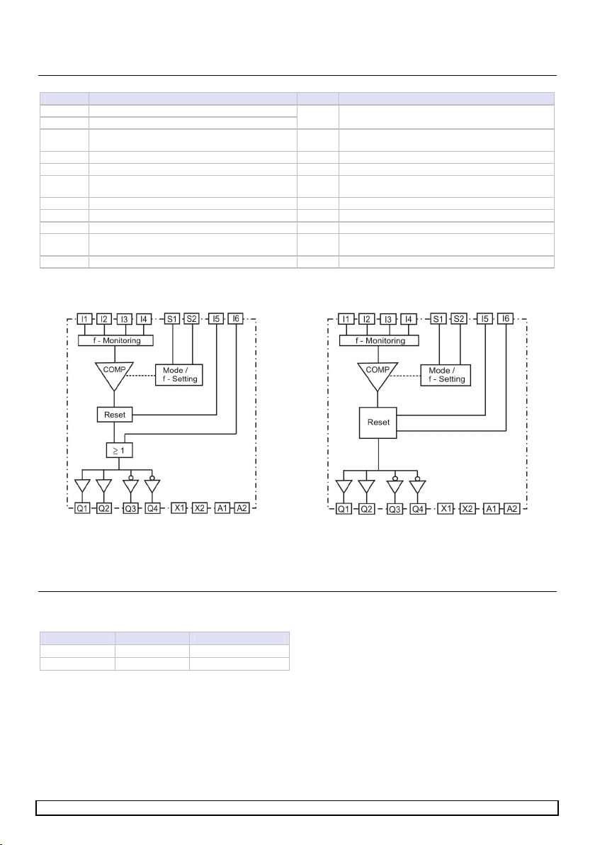
Einstellung des Stillstandswächters (Schema)
SNS 4074K
SNS 4084K
Hinweis zu den Ausgängen
Die Ausgänge Q1/Q2 können bis maximal SIL 3 eingesetzt
werden.
Die Ausgänge Q3/Q4 können zur Ansteuerung magnetkraft-
verriegelter Zuhalteeinrichtungen bis SIL 1 eingesetzt werden.
X1, X2 sind nicht sichere Halbleiter-Ausgänge.
X1 signalisiert Fehlerzustände.
X2 signalisiert den Logikzustand von A sowie die
RESET-Anforderung durch I5.
Einstellung der zu überwachenden Drehzahl
Die Stillstandfrequenz wird mit den zwei Drehschaltern „x“
und „y“ eingestellt.
Gerätevariante Drehschalter Freq. [Hz]
0,1–9,9Hz 00 / 01– 99 0,1 / 0,1–9,9
0,5–99Hz 00 / 01– 99 0,5 / 01–99
"ENTER"-Taste: Aktivieren des Funktionsbausteins und
Steuerkreisfunktionen
Die gewünschte Betriebsart, Drehzahl (an den Drehschal-
tern) und die Steuerkreisfunktion (durch Außenbeschaltung
an S1, S2, I5) einstellen.
Dann bei gedrückter ENTER-Taste die Betriebsspannung
anlegen, die Anzeige ERR blinkt (max. 3 s).
Die ENTER-Taste loslassen, während die Anzeige ERR blinkt.
(Wird die ENTER-Taste länger als 3 s gedrückt, wird ein
Fehler erkannt.)
Die gewählte Betriebsart, Drehzahl und RESET-Funktion ist
dann gespeichert und aktiv.

Doc. # BA000624 – 04/2012 (Rev. D) SNS 4074K/4084K DE 3
RESET / BYPASS-Funktion I5/I6 (SNS 4074K)
Die Funktion autom.(high)/manueller (low) Reset wird bei der
Aktivierung des Bausteins festgelegt. siehe ENTER-Taste.
automatischer RESET: Ein Highsignal an I5 (offen) gibt das
Komparatorsignal an die Ausgänge weiter.
manueller RESET:Ein Highimpuls an I5 gibt die Freigabe des
Komparators an die Ausgänge weiter.
Mit der Bypass-Funktion (ODER) am Eingang I6 des SNS
4074K kann die Weitergabe der Resetsignale beeinflusst
werden. Ist der Eingang I6 beschaltet (HIGH) sind die Ausgän-
ge Q1und Q2 dauerhaft HIGH und Q3 und Q4 dauerhaft LOW.
Die Erzeugung des Bypass-Signals muss mindestens den
gleichen Sicherheitsanforderungen genügen, wie die einge-
stellte Betriebsart und deren Sicherheitsfunktion.
RESET / Anlaufüberbrückung I5/I6 (SNS 4084K)
Die Funktion autom.(high)/manueller (low) Reset wird bei der
Aktivierung des Bausteins festgelegt. siehe ENTER-Taste.
automatischer RESET: Ein Highsignal an I5 (offen) gibt das
Komparatorsignal an die Ausgänge weiter. Mit I6 kann diese
Weitergabe deaktiviert werden (I6= LOW)
manueller RESET: Ein Highimpuls an I5 gibt die Freigabe des
Komparators an die Ausgänge weiter. Ein Highimpuls an I6
setzt diese Freigabe wieder zurück.
Verhalten des Gerätes im Fehlerfall
Die Erkennung von zufälligen oder systematischen Systemfeh-
lern innerhalb des Systems oder in dessen Ansteuerung führt
zur Abschaltung. Dabei werden alle sicherheitsgerichteten
Ausgangskreise abgeschaltet und die LED ERR des Moduls
leuchtet bzw. blinkt. Zusätzlich werden über den Meldeaus-
gang X1 und den LEDs der Eingänge Fehlercodes ausgegeben.
Es werden drei Fehlerkategorien unterschieden:
ERR leuchtet: Systemfehler, alle Ausgänge werden abge-
schaltet.
ERR blinkt: schwere Fehler, alle Ausgänge werden
abgeschaltet.
ERR aus: kein Fehler bzw. leichte Ablauffehler
Detaillierte Angaben finden Sie im Handbuch.
Die Abschaltung lässt sich ggf. anwenderseitig durch Beseiti-
gung eines Fehlers (z.B. in der Ansteuerung) und durch Aus-
und Wiedereinschalten der Betriebsspannung aufheben.
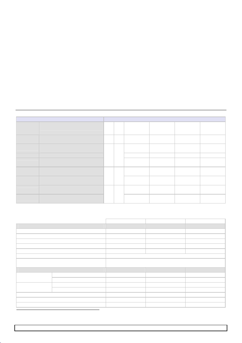
Einstellung der Betriebsart
Eingangszuordnung
Betriebsart Geber S1
S2 I1 I2 I3 I4
A-1
A-2 Inkrementalgeber mit HTL-Ausgang low low Geber 1 Geber 2 Geber 1
invertiert
Geber 2
invertiert
B-1 Inkrementalgeber mit HTL-Ausgang
Sensor mit PNP-Ausgang Geber 1 Geber 1
invertiert low low
B-2 1) Sensor mit PNP-Ausgang Geber 1 Geber 2 low high
B-3 Inkrementalgeber mit HTL-Ausgang
Sensor mit PNP-Ausgang
low high
Geber 1 low high low
C-1 Inkrementalgeber mit HTL-Ausgang
Sensor mit PNP-Ausgang Geber 1 PLC-Signal Geber 1
invertiert low
C-1 Inkrementalgeber mit HTL-Ausgang
Sensor mit PNP-Ausgang
high low
Geber 1 statisches
HIGH-Signal
Geber 1
invertiert high
D-1 Inkrementalgeber mit HTL-Ausgang
Sensor mit PNP-Ausgang Geber 1 PLC-Signal low low
D-1 Inkrementalgeber mit HTL-Ausgang
Sensor mit PNP-Ausgang
high high
Geber 1 statisches
HIGH-Signal low high
1) In der Betriebsart B-2 kann der angegebene Sicherheitslevel nur eingehalten werden, wenn die Sensorleitungen Einzelmantellei-
tungen sind und diese geschützt verlegt sind.
Technische Daten
min typ max
Versorgungskreis (A1, A2)
Betriebsspannung UB, DC 19,2 V DC 24 V DC 30 V DC
Nennspannung UN24 V DC
Restwelligkeit Uss 3,0 V
Bemessungsleistung DC 2,5W 3 W
Spitzenstrom IP25 A
Bereitschaftszeit ton (nach Anlegen von UB) 5sec + 1/fST
Sicherung Klasse gG oder Leitungsschutzschalter 4 A (gG)
Eingangskreis (I2, I3, I4, I5, I6, S1, S2)
Ue(HIGH 13,0 V 30 VEingangsspannung
Ue(LOW) -0,5 V 5,0 V
Ie(HIGH) 2,4 mA 3,0 mA 3,8 mAEingangsstrom
Ie(LOW) -2,5 mA 2,1 mA
Eingangskapazität, CIN
10 nF
Eingangswiderstand RIN
7200 Ω
Einschaltdauer tE52 ms
70 ms
Ausschaltdauer tA52 ms
70 ms
Unterbrechungszeit von Ue(Testimpulse) 4,0 ms
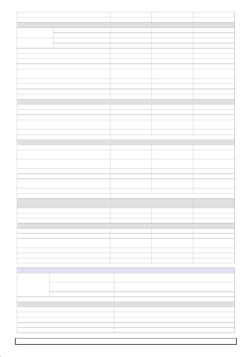
Eingangskreis (I1, I2, I3, I4)
Ue(High) 13,0V 30 VEingangspannung
Ue(LOW) -0,5V 5 V
Eingangsstrom Ie(HIGH) 2,4 mA 3,8 mA

Doc. # BA000624 – 04/2012 (Rev. D) SNS 4074K/4084K DE 4
Ie(LOW) -2,5 mA 2,1 mA
Eingangskapazität, CIN
10 nF
Eingangswiderstand RIN
7200 Ω
Grenzfrequenz
2 kHz
Frequenzänderung
21 kHz/s
Messgenauigkeit der Frequenzmessung 1%
(<1Hz)
6 %
(<50Hz)
12 %
(99Hz)
Impulsdauer LOW-Pegel (für f<100Hz) > 600 μs
Impulsdauer High-Pegel (für f<100Hz) > 600 μs
LOW-Pegel (für 100Hz< f< 2kHz) > 200 μs
High-Pegel (für 100Hz< f< 2kHz) > 200 μs
Ausgangskreis (X1, X2)
Ausgangsspannung 18,4 V
30,0 V
Ausgangsstrom 150 mA
Lastkapazität CL1000 nF
Leitungswiderstand RL,
wirksam beim Entladen von CL
100 Ω
Leitungslänge (einfach, 1,5mm2) 100 m
Kurzschlussverhalten unbedingt kurzschlussfest
Ausgangskreis (Q1, Q2, Q3, Q4)
Ausgangsspannung 18,4V 30V
Ausgangsstrom IQn, TU45 °C (resistiv / induktiv)
Ausgangsstrom IQn, TU55 °C 1,6A 2A / 1A
1,6A
Summenstrom ÓIQn, TU45 °C
Summenstrom ÓIQn, TU55 °C 4 A
3,2 A
Testimpulsbreite, tTI,HL 400μs 650 μs
Lastkapazität CL
500 nF
Induktive Abschaltenergie E (E = 0,5 * L * I2) 370 mJ
Leitungslänge (einfach, 1,5mm2) 100 m
Kurzschlussverhalten unbedingt kurzschlussfest
Ansprechzeit (tAN) bei Drehzahlüberschreitung
für Stillstandsfrequenz (fst) 0,1HZ - 99HZ
bei Tastverhältnis 1:1 (3:2) 1 / fst 1,8 (1,6) / fst
plus die interne Verarbeitungszeit 8ms 12 ms
Fehlererkennungszeit
Kurzschluss nach GND, UB
Inkrementalgeber mit invertierten Ausgang 52ms 116 ms
Sensoren mit Tastverhältnis 3:2 (Betriebsart B-2) 52ms 3/f
Kurzschluss nach UB(Eingang intern) 576 ms
Kurzschluss nach UB(Ausgang) 576 ms
Fehler in der Spannungsversorgung 576 ms
Allgemeine Daten
Versorgungskreis - Eingangskreis nein
Versorgungskreis - Ausgangskreis nein
Galvanische
Trennung
Eingangskreis - Ausgangskreis nein
Gewicht 0,16 kg
Klimatische Bedingungen
Klimatische Bedingungen nach EN 61131-2
Betriebsumgebungstemperatur TB-25C bis +55C
Lagertemperatur -25C bis +70C
Relative Luftfeuchte 10% bis 95%, keine Betauung
Luftdruck im Betrieb 860 hPa bis 1060 hPa
Mechanische Festigkeit
Schwingen nach EN 60068-2-xx (weitere Informationen siehe Handbuch)
Elektrische Sicherheit
Schutzart nach EN 60529 Gehäuse/Klemmen IP 40 / IP 20
Fingersicher EN 50274
Luft-/Kriechstrecken EN 60664-1
EMV nach EN 61000-4-xx (weitere Informationen siehe Handbuch)
Überspannungskategorie III
Verschmutzungsgrad 2 innerhalb, 3 außerhalb

Doc. # BA000624 – 04/2012 (Rev. D) SNS 4074K/4084K DE 5
Klemmen- und Anschlussdaten Schraubklemmen Federkraftklemmen
Eindrähtig oder feindrähtig 1 × 0,14–2,5 mm² /
2 × 0,14–0,75 mm²
2 × 0,2–1,5 mm²
Feindrähtig mit Aderendhülse nach DIN 46228 1 × 0,25–2,5 mm² /
2 × 0,25–0,5 mm²
2 × 0,25–1,5 mm²
(Trapezverpressung)
AWG 26–14 24–16
Maximales Anzugsdrehmoment 0,5–0,6 Nm (5–7 lbf-in) —
Abisolierlänge max. 8 mm
Klemmenschaltbild
Montage, Demontage
Montage
1
Gerät auf die Hutschiene
einhängen.
2
Durch leichten Druck in Pfeil-
richtung Gerät auf die Hut-
schiene aufschnappen.
Demontage
3
Gerät in Pfeilrichtung herunter-
drücken.
4
Im heruntergedrückten Zustand
Gerät in Pfeilrichtung aus der
Verrastung lösen und von der
Hutschiene nehmen.
Abmessungen
SNS 4084K-A DC 24V
SNS 4084K-C DC 24V

Operating Instructions (translation of the original instructions)
SNS 4074K
SNS 4084K
Zero-speed monitor
Doc. # BA000624 – 04/2012 (Rev. D) SNS 4074K/4084K EN 6
Zero-speed monitor
Application up to SIL 3 according to EN 61508, EN 62061 or PL e / Category 4 according to EN
ISO 13849-1
Manual or automatic reset
Eight safe inputs and four safe semiconductor outputs
2 kHz cutoff frequency
Adjustable standstill frequency
0.1 Hz…9.9 Hz (0.1 Hz steps) and 0.5 Hz …99 Hz (1 Hz steps)
Sensors: Proximity switches with PNP-output (plus switching)
Incremental encoder with HTL-output
Device versions
SNS 4074K-A 0.1–9.9 Hz R1.188.3620.0 SNS 4084K-A 0.1–9.9 Hz R1.188.3660.0
SNS 4074K-C 0.1–9.9 Hz R1.188.3630.0 SNS 4084K-C 0.1–9.9 Hz R1.188.3670.0
SNS 4074K-A 0.5–99 Hz R1.188.3640.0 SNS 4084K-A 0.5–99 Hz R1.188.3480.0
SNS 4074K-C 0.5–99 Hz R1.188.3650.0 SNS 4084K-C 0.5–99 Hz R1.188.3490.0
…-A: with screw terminals, pluggable; …-C: with spring-loaded terminals, pluggable
Further Documentation
For the planning, commissioning and operation of the device, please observe the information in the
documentation "Manual SNS 4084K/4074K Standstill Monitor" (Doc. No.: BA000506).
SAFETY REGULATIONS
The installation, commissioning, modification and retrofit-
ting must only be performed by a qualified electrician.
Disconnect the device / the system from the power supply
before starting work. In the case of installation and system
errors, mains voltage can be present on the control circuit in
the case of non-galvanically isolated devices.
Observe the electrotechnical and professional trade associa-
tion safety regulations for the installation of the equipment.
Opening the case or other manipulation voids any warranty.
ATTENTION
In the case of improper use or any use other than for the
intended purpose, the device must no longer be used and
any warranty claim is void. Invalidating causes can be:
strong mechanical loading of the device such as, e.g. in
the case of falling or voltages, currents, temperatures, hu-
midity outside the specification.
Always check all safety functions in accordance with the
applicable regulations during initial commissioning of your
machine / system and observe the specified inspection
cycles for safety devices.
Take the following safety precautions before starting
installation / assembly or dismantling:
1. Disconnect the device / the system from the power sup-
ply before starting work.
2. Secure the machine / system against being switched on
again.
3. Confirm that no voltage is present.
4. Ground the phases and short to ground briefly.
5. Cover and shield neighbouring live parts.
Limited contact protection!
Protection class according to EN 60529.
Case / terminals: IP 40 / IP 20.
Finger-proof according to EN 50274.
Proper Use
The units must only be used as components of safety devices
on machines intended to protect persons, material and ma-
chines.
Only use the unit in accordance with its intended purpose. Also,
pay particular attention to the information in the technical data.
The frequencies present at the inputs I1, I2, I3 and
I4 must not exceed 2 kHz (cutoff frequency).
NOTE
The SIL according to EN 61508 / EN 62061 or PL / Category
according to EN ISO 13849-1 depending on the external
wiring, the choice of control devices and their location on
the machine.
In applications with a low demand of the safety function, a
proof-test once a year has to be implemented (The supply
voltage of the device has to be switched off and on again
and the safety function of the device has to be activated to
verify the safety function).
The device must be protected with a fuse 4 A Operating
Class gG or a circuit breaker 4 A Tripping Characteristics B
or C.
Installation (see also "Assembly")
NOTE
The devices must be installed in a switch cabinet with a
protection class of at least IP 54.
The installation is made on a mounting rail
according to EN 50022-35.
The mounting rail must be connected to protective earth
(PE).
The external power supply must comply with the regulations
for low voltages with safe separation (SELV, PELV according
to IEC 60536) and EN 50178 (Electrical equipment for use in
power installations).
External loads must be equipped with a suitable protection
circuit for the load (e.g. RC elements, varistors, suppressors)
in order to reduce electromagnetic interference and to in-
crease the service life of the output switching elements.
Functional Description
In the SNS 4084K/4074K there are four operating mode
groups A, B, C, D available for safe speed monitoring tasks (see
manual):
Zero-speed monitoring (A, B)
Diverse zero-speed monitoring (C, D) with PLC-signal
7

Doc. # BA000624 – 04/2012 (Rev. D) SNS 4074K/4084K EN 7
Connections and indicators (see also the section "Terminal Diagram")
Terminal Function LED Meaning, if LED lights
A1 Operating voltage connection UB
A2 Operating voltage connection Ground
PWR UBis present
X1, X2 Semiconductor signal outputs for indicating and
evaluating operating and error statuses
S1 Input for function selection (operating mode) S1 High signal is present
S2 Input for function selection (operating mode) S2 High signal is present
I1 – I4
I2 – I4
Inputs for sensor transmitter or
Input for function selection (operating mode)
I1 – I4 High signal is present
I5 Input for RESET function I5 High signal is present
I6 Input for enable/start delay I6 High signal is present
Q1 / Q2 Outputs (semiconductors), safety related Q1 / Q2 High signal is present
Q3 / Q4 Inverted outputs (semiconductors), safety related Q3 / Q4 High signal is present
ERR Error (see manual BA000506)
Settings of the standstill monitor (diagram)
SNS 4074K
SNS 4084K
Information on the outputs
The outputs Q1/Q2 can be used up to SIL 3.
The outputs Q3/Q4 can be used for controlling magnetically
operated interlocks up to SIL 1.
X1, X2 are not safe semiconductor outputs.
X1 signals error states.
X2 signals the logic state of A and the RESET request by
I5.
Setting of the speed to be monitored
The standstill frequency is set using the two rotary switches
"x" and "y".
Device Variants Rotary switch Freq. [Hz]
0.1–9.9 Hz 00 / 01– 99 0.1 / 0.1–9.9
0.5–99 Hz 00 / 01– 99 0,5 / 01–99
"ENTER" button: Activation of the function block and
control circuit functions
Set the required operating mode, speed (at the rotary
switches) and the control circuit function (using external
wiring at S1, S2, I5).
Then apply the operating voltage with the ENTER button
pressed; the ERR indicator flashes (max. 3 s).
Release the ENTER button while the ERR indicator is flash-
ing (an error is detected if the ENTER button is pressed for
longer than 3 s).
The selected operating mode, speed and RESET function are
then saved and active.
RESET / BYPASS function I5/I6 (SNS 4074K)
The automatic(high)/manual (low) Reset function is defined
during the activation of the POU, see ENTER button.
automatic RESET: A High signal at I5 (open) transmits the
comparator signal to the outputs.
manual RESET:A High pulse at I5 transmits the enable of the
comparator to the outputs.
The transfer of the Reset signals can be influenced using the
Bypass function (ODER) at the input I6 of the SNS 4074K, If
the input I6 is wired (HIGH), the outputs Q1 and Q2 are
permanently HIGH and Q3 and Q4 permanently LOW. The
generation of the bypass signal has to fulfill the same safety
requirements as the operating mode and the designated safety
function.
RESET / Start-up bridging I5/I6 (SNS 4084K)
The automatic(high)/manual (low) Reset function is defined
during the activation of the POU, see ENTER button.
automatic RESET: A High signal at I5 (open) transmits the
comparator signal to the outputs. This transfer can be disabled
with I6 (I6 = LOW)

Doc. # BA000624 – 04/2012 (Rev. D) SNS 4074K/4084K EN 8
manual RESET: A High pulse at I5 transmits the enable of the
comparator to the outputs. A High pulse at I6 revokes this
enable.
Behaviour of the device in the case of an error
The detection of random or systematic system errors in the
system or its control results in deactivation. In doing so, all
safety-oriented output circuits are switched off and the ERR
LED of the module lights or flashes. Error codes are also
output via the signal output X1 and the LEDs of the inputs.
Three error categories are distinguished:
ERR lights: system error, all outputs are deactivated.
ERR flashes: serious error, all outputs are deactivated.
ERR off: no errors or minor process errors
Detailed information can be found in the manual.
The deactivation can be revoked if necessary by the user by
elimination of an error (e.g. in the control) and by switching off
the operating voltage and then switching it on again.
Setting the operating mode
Input Assignment
Operating
mode Sensor S1
S2 I1 I2 I3 I4
A-1
A-2 Incremental encoder with HTL output low low Sensor 1 Sensor 2 Sensor 1
inverted
Sensor 2
inverted
B-1 Incremental encoder with HTL output
Sensor with PNP output Sensor 1 Sensor 1
inverted low low
B-2 1) Sensor with PNP output Sensor 1 Sensor 2 low high
B-3 Incremental encoder with HTL output
Sensor with PNP output
low high
Sensor 1 low high low
C-1 Incremental encoder with HTL output
Sensor with PNP output Sensor 1 PLC signal Sensor 1
inverted low
C-1 Incremental encoder with HTL output
Sensor with PNP output
high low
Sensor 1 static
HIGH signal
Sensor 1
inverted high
D-1 Incremental encoder with HTL output
Sensor with PNP output Sensor 1 PLC signal low low
D-1 Incremental encoder with HTL output
Sensor with PNP output
high high
Sensor 1 static
HIGH signal low high
1) In operating mode B-2, the specified safety level can only be adhered to if the sensor lines are individually sheathed and laid so
that they are protected.
Technical Data
min typical max
Power circuit (A1, A2)
Operating voltage UB, DC 19,2 V DC 24 V DC 30 V DC
Rated voltage UN24 V DC
Residual ripple Uss 3.0 V
Rated power DC 2.5 W 3.0 W
Peak current IP25 A
Ready time ton (after applying UB) 5sec. + 1/fST
Fuse Class gG or circuit breaker 4 A (gG)
Input circuit (I2, I3, I4, I5, I6, S1, S2)
Ue(HIGH 13.0 V 30 VInput voltage
Ue(LOW) -0.5 V 5.0 V
Ie(HIGH) 2.4 mA 3.0 mA 3.8 mAInput current
Ie(LOW) -2.5 mA 2.1 mA
Input capacitance, CIN
10 nF
Input resistance RIN
7200 Ω
Duty cycle tE52 ms
70 ms
Break time tA52 ms
70 ms
Interruption time of Ue(test pulses) 4.0 ms
Input circuit (I1, I2, I3, I4)
Ue(High) 13.0 V 30 VInput voltage
Ue(LOW) -0.5 V 5 V
Ie(HIGH) 2.4 mA 3.8 mAInput current
Ie(LOW) -2.5 mA 2.1 mA
Input capacitance, CIN
10 nF
Input resistance RIN
7200 Ω
Cutoff frequency 2 kHz
Frequency change 21 kHz/s
Measurement accuracy of the frequency measurement 1%
(<1Hz)
6 %
(<50Hz)
12 %
(99Hz)
Pulse duration LOW level (for f<100 Hz) > 600 μs
Pulse duration High level (for f<100 Hz) > 600 μs

Doc. # BA000624 – 04/2012 (Rev. D) SNS 4074K/4084K EN 9
LOW level (for 100 Hz< f< 2 kHz) > 200 μs
High level (for 100 Hz< f< 2 kHz) > 200 μs
Output circuit (X1, X2)
Output voltage 18,4 V 30.0 V
Output current 150 mA
Load capacitance CL1000 nF
Line resistance RL,
effective during discharge of CL
100 Ω
Line length (single, 1.5 mm2) 100 m
Short-circuit behaviour strictly short-circuit protected
Output circuit (Q1, Q2, Q3, Q4)
Output voltage 18,4 V 30 V
Output current IQn, TU≤45 °C (resistive / inductive)
Output current IQn, TU≤55 °C
1.6 2.0 A / 1,0 A
1,6 A
Sum current ΣIQn, TU≤45 °C
Sum current ΣIQn, TU≤55 °C
4.0 A
3.2 A
Test pulse width tTI,HL
400 μs 650 μs
Test pulse period duration TPI,HL
192 ms
Load capacitance CL
500 nF
Inductive cutoff energy E (E = 0.5 * L * I2)
370 mJ
Line length (single, 1.5 mm2) 100 m
Short-circuit behaviour strictly short-circuit protected
Response time (tAN) for overspeed
for standstill frequency (fst) 0.1 HZ - 99 HZ
for duty cycle 1:1 (3:2) 1 / fst 1,8 (1,6) / fst
plus the internal processing time 8 ms 12 ms
Error detection time
Short circuit to GND, UB
Incremental encoder HTL 52 ms 116 ms
Sensors with PNP output (duty cycle 3:2, Mode B-2) 52 ms 3/f
Short circuit to UB(internal input) 576 ms
Short circuit to UB(output) 576 ms
Error in the power supply 576 ms
General Data
Power circuit - input circuit no
Power circuit - output circuit no
Electrical
isolation
Input circuit - output circuit no
Weight 0.16 kg
Climatic conditions
Climatic conditions according to EN 61131-2
Ambient operating temperature TB-25C to +55C
Storage temperature -25C to +70C
Relative humidity 10% to 95%, no moisture condensation
Air pressure in operation 860 hPa to 1060 hPa
Mechanical strength
Vibration according to EN 60068-2-xx (see manual for further information)
Electrical safety
Protection class according to EN 60529 case/terminals IP 40 / IP 20
Finger-proof EN 50274
Air gap/Creepage paths EN 60664-1
EMC according to EN 61000-4-xx (see manual for further information)
Surge voltage category III
Degree of soiling 2 inside, 3 outside
Terminals and connection data Screw clamp terminals Spring-loaded terminals
Single-core or finely stranded 1 × 0.14–2.5 mm² /
2 × 0.14–0.75 mm²
2 × 0.2–1.5 mm²
Finely stranded with wire-end ferrule according
to DIN 46228
1 × 0.25–2.5 mm² /
2 × 0.25–0.5 mm²
2 × 0.25–1.5 mm²
(trapezoid crimping)
AWG 26–14 24–16
Maximum tightening torque 0,5–0,6 Nm (5–7 lbf-in)
Stripping length max. 8 mm

Doc. # BA000624 – 04/2012 (Rev. D) SNS 4074K/4084K EN 10
Terminal diagram
Assembly, Disassembly
Assembly
1
Attach device to DIN rail.
2
Press the device carefully onto
the DIN rail (in direction of
arrow) until it locks into place.
Disassembly
3
Push device down (in direction
of arrow)
4
Release device and remove it
from the DIN rail (see arrow)
Dimension Diagram
SNS 4084K-A DC 24V
SNS 4084K-C DC 24V

Mode d'emploi (Traduction de la notice originale)
SNS 4074K
SNS 4084K
Détecteur d'arrêt
Doc. # BA000624 – 04/2012 (Rev. D) SNS 4074K/4084K FR 11
Détecteur d'arrêt
Application jusqu'à SIL 3 selon EN 61508, EN 62061 ou PL e / catégorie 4 selon la norme EN ISO
13849-1
Démarrage manuel ou automatique
Huit entrées et quatre sorties semi-conducteur sécurisées
Fréquence limite 2 kHz
Fréquence d'arrêt réglable
de 0,1 Hz à 9,9 Hz (par pas de 0,1 Hz) et de 0,5 Hz à 99 Hz (par pas de 1 Hz)
Capteurs / Codeurs : Détecteur de proximité avec sortie PNP (commutation potentiel positif)
Codeur incrémental avec sortie HTL
Versions des appareils
SNS 4074K-A 0,1–9,9 Hz R1.188.3620.0 SNS 4084K-A 0,1–9,9 Hz R1.188.3660.0
SNS 4074K-C 0,1–9,9 Hz R1.188.3630.0 SNS 4084K-C 0,1–9,9 Hz R1.188.3670.0
SNS 4074K-A 0,5–99 Hz R1.188.3640.0 SNS 4084K-A 0,5–99 Hz R1.188.3480.0
SNS 4074K-C 0,5–99 Hz R1.188.3650.0 SNS 4084K-C 0,5–99 Hz R1.188.3490.0
…-A : avec bornes à vis, enfichables ; …-C : avec bornes à ressort, enfichables
Documents supplémentaires
Pour la conception, la mise en service et l'exploitation correctes de l'appareil, veuillez tenir compte
des indications du « Manuel du détecteur d'arrêt SNS 4084K / 4074K » (réf. du doc. : BA000506).
CONSIGNES DE SÉCURITÉ
Seul un électricien qualifié est habilité à effectuer le mon-
tage, la mise en service, la modification et le rééquipement !
Avant de commencer les travaux, mettre l'appa-
reil/l'installation hors tension ! En cas de défauts de montage
et de l'installation, avec les modules non séparés galvani-
quement, le circuit de commande peut être sous potentiel
réseau !
Pour l'installation des modules, veuillez observer les consi-
gnes de sécurité en matière d'électronique et celles de la
caisse professionnelle d'assurance-accidents.
L'ouverture de l'appareil ou toute autre manipulation
entraîne l'extinction de la garantie.
ATTENTION
En cas d'utilisation incorrecte ou d'utilisation non conforme
à l'usage prévu, le module ne doit plus être utilisé et tout
droit à la garantie est annulé. Exemples d'effets inadmissi-
bles :
Forte sollicitation mécanique du module, comme p. ex. en
cas de chute, de tensions, de courants, de températures,
d'humidité hors spécification.
Lors de la première mise en service de votre machine/
installation, veillez à vérifier systématiquement que toutes
les fonctions de sécurité sont conformes aux prescriptions
applicables et observez les cycles de contrôle préconisés
pour les dispositifs de sécurité.
Avant de procéder à l'installation, au montage ou au démon-
tage, veuillez appliquer les mesures de sécurité suivantes :
1. Avant de commencer les travaux, mettre l'appa-
reil/l'installation hors tension !
2. Protéger la machine/l'installation contre toute remise en
marche intempestive !
3. S'assurer de l'absence de tension !
4. Mettre les phases à la terre et les court-circuiter !
5. Recouvrir et isoler les parties sous tension voisines !
Protection limitée contre les contacts accidentels !
Indice de protection conforme à la norme EN 60529.
Boîtier / bornes : IP 40 / IP 20.
Protection des doigts selon la norme EN 50274.
Utilisation conforme à l'usage prévu
Les appareils ne doivent être mis en œuvre qu'en tant qu'élé-
ment de dispositifs de protection sur des machines et sont
dédiés à la protection des personnes, du matériel et des
machines. N'utiliser l'appareil que conformément à son usage
prévu. À cet effet, respecter plus particulièrement les indica-
tions fournies dans les caractéristiques techniques.
Les valeurs de fréquence présentes aux entrées I1,
I2, I3 et I4 ne doivent pas dépasser 2 kHz (fré-
quence limite) !
REMARQUES
Le SIL selon EN 61508 / EN 62061 ou la catégorie PL selon
la norme EN ISO 13849-1 dépendent du circuit extérieur, du
choix de l'émetteur d'ordres et de son agencement sur la
machine.
En cas d'exigences d'utilisation moindres de la fonction de
sécurité, un test de vérification doit être effectué une fois par
an (activation/désactivation de la tension de service de l'ap-
pareil et déclenchement de la fonction de sécurité, par ex.
via un dépassement de la fréquence).
L'appareil doit être protégé par un fusible 4 A de la classe de
fonctionneéent gG ou un disjoncteur de protection de circuit
4 A à caractéristique de déclenchement B ou C.
Installation (voir aussi « Montage »)
REMARQUES
Le montage des modules doit s'effectuer dans une armoire
de commande possédant un indice de protection minimal
d'IP 54.
Le montage est réalisé sur un rail porteur
selon EN 50022-35.
Le rail porteur doit être relié au conducteur de protection
(PE).
Le bloc d'alimentation externe doit être conforme aux
prescriptions pour les basses tensions à séparation sécuri-
sée (TBTS selon CEI 60536) et à la norme EN 50178 (équi-
pement d'installations à courant fort avec matériel d'exploi-
tation électronique).
Les charges externes doivent être équipées d'un circuit de
protection adapté à la charge (p. ex. circuits RC, varistances,
suppresseurs) afin de réduire les perturbations électroma-
gnétiques et d'augmenter la durée de vie des modules de
coupure de sortie.
7

Doc. # BA000624 – 04/2012 (Rev. D) SNS 4074K/4084K FR 12
Description de la fonction
Le SNS 4084K/4074K dispose de quatre catégories de modes
de fonctionnement
A, B, C, D aux tâches de surveillance sécurisée de la vitesse de
rotation (voir manuel) :
Surveillance du temps d'arrêt (catégories de modes de
fonctionnement A, B)
Surveillance d'arrêt diversitaire (catégories de modes de
fonctionnement C, D) avec signal API
Raccordements et indications (se référer également à la section « Schéma de connexion des bornes »)
Borne Fonction LED Signification, lorsque la LED est allumée
A1 Raccordement tension de service UB
A2 Raccordement tension de service Masse
PWR UBest présente
X1, X2 Sorties de signalisation à semi-conducteur pour
l'affichage et l'évaluation des états de fonction-
nement et des défauts.
S1 Entrée pour sélection de fonction (mode de
fonctionnement)
S1 Signal High est présent
S2 Entrée de sélection de fonction (mode de fonc-
tionnement)
S2 Signal High est présent
I1 – I4
I2 – I4
Entrées pour capteur-émetteur ou
Entrée de sélection de fonction (mode de fonc-
tionnement)
I1 – I4 Signal High est présent
I5 Entrée de fonction de réinitialisation RESET I5 Signal High est présent
I6 Entrée de validation / temporisation de démarrage I6 Signal High est présent
Q1 / Q2 Sorties (semi-conducteur), sécurisées Q1 / Q2 Signal High est présent
Q3 / Q4 Sorties inversées (semi-conducteur), sécurisées Q3 / Q4 Signal High est présent
ERR Défaut (voir manuel BA000506)
Réglage du détecteur d'arrêt (schéma)
SNS 4074K
SNS 4084K
Remarques relatives aux sorties
Les sorties Q1 / Q2 peuvent être utilisées jusqu'à SIL 3 max.
Les sorties Q3 / Q4 peuvent être utilisées pour la commande
de dispositifs de verrouillage magnétiques jusqu'à SIL 1.
X1, X2 ne sont pas des sorties semi-conductrices sécuri-
sées.
X1 signale les défauts.
X2 signale l'état logique de A ainsi que la demande de
réinitialisation (RESET) via I5.
Réglage de la vitesse de rotation à surveiller
La fréquence d'arrêt se règle à l'aide de deux commutateurs
rotatifs « x » et « y ».
Variante de
l'appareil
Commutateur
rotatif
Fréq. [Hz]
0,1–9,9 Hz 00 / 01– 99 0,1 / 0,1–9,9
0,5–99 Hz 00 / 01– 99 0,5 / 01–99
Touche « ENTRÉE : Activation du module fonctionnel et
des fonctions du circuit de commande
Définir le mode de fonctionnement, la vitesse de rotation (au
niveau des commutateurs rotatifs) et la fonction du circuit de
commande (via le circuit extérieur à S1, S2, I5) souhaités.
Appliquer ensuite la tension de service en maintenant la
touche ENTRÉE enfoncée, le message ERR clignote (3 s.
max.).
Lâcher la touche ENTRÉE pendant que le message ERR
clignote. (Si la touche ENTRÉE est maintenue enfoncée
pendant plus de 3 s, un défaut est reconnu.)
Le mode de service, la vitesse de rotation et la fonction RESET
souhaités sont alors enregistrés et actifs.
Doc. # BA000624 – 04/2012 (Rev. D) SNS 4074K/4084K FR 13
Fonction RESET / BYPASS I5/I6 (SNS 4074K)
La fonction RESET autom. (high) / manuelle (low) est définie
lors de l'activation du module. Voir la touche ENTRÉE.
RESET automatique : Un signal High présent sur I5 (ouvert)
transfère le signal de comparateur aux sorties.
RESET manuel : une impulsion High présente sur I5 transfère
la validation du comparateur aux sorties.
La transmission des signaux RESET peut être influencée par la
fonction Bypass (OU) à l'entrée I6 du SNS 4074K. Si l'entrée I6
est commutée (High), les sorties Q1 et Q2 sont constamment
HIGH et les sorties Q3 et Q4 constamment LOW. Les exigen-
ces de sécurité pour la génération du signal Bypass sont au
minimum identiques à celles qui sont fixées pour le mode de
fonctionnement et la fonction de sécurité correspondante.
RESET / Temporisation de démarrage I5 / I6 (SNS 4.084K)
La fonction RESET autom. (high) / manuelle (low) est définie
lors de l'activation du module. Voir la touche ENTRÉE.
RESET automatique : Un signal High présent sur I5 (ouvert)
transfère le signal de comparateur aux sorties. Cette transmis-
sion peut être désactivée via I6 (I6= LOW)
RESET manuel : une impulsion High présente sur I5 transfère
la validation du comparateur aux sorties. Une impulsion High
présente sur I6 restaure cette validation.
Comportement de l'appareil en cas de dysfonctionnement
La détection de dysfonctionnments aléaroires ou systémati-
ques dans le système ou dans sa comma,de entraîne la
désactivation. Tous les circuits de sortie sécurisés sont alors
désactivés et la LED ERR du module s'allume ou clignote. De
plus, des codes d'erreurs sont affichés via la sortie de signali-
sation X1 et les LED des entrées.
Il existe trois catégories d'erreurs :
ERR allumé : Défaut du système, toutes les sorties sont
coupées.
ERR clignote : Défaut grave, toutes les sorties sont coupées.
ERR éteint : Pas de défaut ou défaut de processus mineur
Vous trouverez des informations plus détaillées dans le
manuel.
Le cas échéant, la désactivation peut être annulée par l'utilisa-
teur par l'élimination d'un dysfonctionnement (p. ex. dans la
commande) et par la désactivation/réactivation de la tension
de service.
Réglage du mode de fonctionnement
Affectation des entrées
Mode de
fonctionne-
ment
Émetteur S1
S2 I1 I2 I3 I4
A-1
A-2 Codeur incrémental avec sortie HTL low low Émetteur 1 Émetteur 2 Émetteur 1
inversé
Émetteur 2
inversé
B-1 Codeur incrémental avec sortie HTL
Capteur avec sortie PNP Émetteur 1 Émetteur 1
inversé low low
B-2 1) Capteur avec sortie PNP Émetteur 1 Émetteur 2 low high
B-3 Codeur incrémental avec sortie HTL
Capteur avec sortie PNP
low high
Émetteur 1 low high low
C-1 Codeur incrémental avec sortie HTL
Capteur avec sortie PNP Émetteur 1 Signal PLC Émetteur 1
inversé low
C-1 Codeur incrémental avec sortie HTL
Capteur avec sortie PNP
high low
Émetteur 1 Signal HIGH
statique
Émetteur 1
inversé high
D-1 Codeur incrémental avec sortie HTL
Capteur avec sortie PNP Émetteur 1 Signal PLC low low
D-1 Codeur incrémental avec sortie HTL
Capteur avec sortie PNP
high high
Émetteur 1 Signal HIGH
statique low high
1) En mode de fonctionnement B-2, le niveau de sécurité donné peut uniquement être maintenu si les câbles des capteurs sont des
câbles mono-gaine blindés.
Caractéristiques techniques
min Type max
Circuit d'alimentation (A1, A2)
Tension de service UB, CC 19,2 V CC 24 V CC 30 V CC
Tension nominale UN24 V CC
Ondulation résiduelle Uss 3,0 V
Puissance assignée CC 2,5 W 3 W
Courant de pointe IP25 A
Temps de disponibilité ton (après application de UB) 5 s.+ 1/fST
Classe de fonctionnement gG ou disjoncteur de
protection de circuit 4 A (gG)
Circuit d'entrée (I2, I3, I4, I5, I6, S1, S2)
Ue(HIGH 13,0 V 30 VTension d'entrée
Ue(LOW) -0,5 V 5,0 V
Ie(HIGH) 2,4 mA 3,0 mA 3,8 mACourant d'entrée
Ie(LOW) -2,5 mA 2,1 mA
Capacité d'entrée, CIN
10 nF
Résistance d'entrée RIN
7200 Ω
Durée d'activation tE52 ms
70 ms
1
Doc. # BA000624 – 04/2012 (Rev. D) SNS 4074K/4084K FR 14
Durée de désactivation tA52 ms
70 ms
Temps d'interruption de Ue(impulsions d'essai) 4,0 ms
Circuit d'entrée (I1, I2, I3, I4)
Ue(High) 13,0 V 30 VTension d'entrée
Ue(LOW) -0,5 V 5 V
Ie(HIGH) 2,4 mA 3,8 mACourant d'entrée
Ie(LOW) -2,5 mA 2,1 mA
Capacité d'entrée, CIN
10 nF
Résistance d'entrée RIN
7200 Ω
Fréquence limite 2 kHz
Changement de fréquence 21 kHz/s
Précision de mesure de la fréquence 1%
(< 1 Hz)
6 %
(< 50 Hz)
12 %
(99 Hz)
Durée d'impulsion niveau LOW (pour f < 100 Hz) > 600 μs
Durée d'impulsion niveau HIGH (pour f < 100 Hz) > 600 μs
Niveau LOW (pour 100 Hz< f< 2 kHz) > 200 μs
Niveau HIGH (pour 100 Hz< f< 2 kHz) > 200 μs
Circuit de sortie (X1, X2)
Tension de sortie 18,4 V 30,0 V
Courant de sortie 150 mA
Capacité de charge CL1000 nF
Résistance de ligne RL,
effectif lors de la décharge de CL
100 Ω
Longueur de ligne (simple, 1,5 mm2) 100 m
Comportement au court-circuit obligatoirement résistant aux courts-circuits
Circuit de sortie (Q1, Q2, Q3, Q4)
Tension de sortie 18,4 V 30 V
Courant de sortie IQn, TU45 °C (résistif / inductif)
Courant de sortie IQn, TU55 °C 1,6 A 2 A / 1 A
1,6 A
Courant cumulé ÓIQn, TU45 °C
Courant cumulé ÓIQn, TU55 °C 4 A
3,2 A
Largeur d'impulsions d'essai, tTI,HL 400 μs 650 μs
Capacité de charge CL
500 nF
Énergie inductive pour le débranchement E (E = 0,5
* L * I2)
370 mJ
Longueur de ligne (simple, 1,5 mm2) 100 m
Comportement au court-circuit obligatoirement résistant aux courts-circuits
Temps de réponse (tAN) en cas de dépassement de la
vitesse de rotation
pour fréquence d'arrêt (fst) 0,1 HZ - 99 HZ
pour taux d'impulsions 1:1 (3:2) 1 / fst 1,8 (1,6) / fst
plus la durée de traitement interne 8 ms 12 ms
Temps d'identification des défauts
Court-circuit selon GND, UB
Codeur incrémental avec sortie inversée 52 ms 116 ms
Capteurs avec taux d'impulsions 3:2 (mode de
service B-2)
52 ms 3/f
Court-circuit selon UB(entrée interne) 576 ms
Court-circuit selon UB(sortie) 576 ms
Défaut d'alimentation en tension 576 ms
Données générales
Circuit d'alimentation - circuit
d'entrée
non
Circuit d'alimentation - circuit de
sortie
non
Séparation
galvanique
Circuit d'entrée - circuit de sortie non
Poids 0,16 kg
Conditions climatiques
Conditions climatiques selon EN 61131-2
Température ambiante de service TB-25C à +55C
Température de stockage -25C à +70C
Humidité relative de l'air 10 % à 95 %, pas de condensation
Pression atmosphérique en fonctionnement 860 hPa à 1060 hPa

Doc. # BA000624 – 04/2012 (Rev. D) SNS 4074K/4084K FR 15
Résistance mécanique
Vibration selon EN 60068-2-xx (voir manuel pour plus d'informations)
Sécurité électrique
Type de protection selon la norme EN 60529 Boîtier /
bornes
IP40 / IP20
Protection des doigts EN 50274
Entrefers / lignes de fuite EN 60664-1
CEM selon EN 61000-4-xx (voir manuel pour plus d'informations)
Catégorie de surtension III
Degré d'encrassement 2 à l'intérieur, 3 à l'extérieur
Données relatives aux bornes et au raccordement Bornes à vis Bornes à ressort
Unifilaire ou à fils de faible diamètre 1 × 0,14–2,5 mm² /
2 × 0,14–0,75 mm²
2 × 0,2–1,5 mm²
À fils fins avec embout conforme à la norme DIN 46228 1 × 0,25–2,5 mm² /
2 × 0,25–0,5 mm²
2 × 0,25–1,5 mm² (sertissage
trapézoïdal)
AWG 26–14 24–16
Couple de serrage maximal 0,5–0,6 Nm (5–7 lbf-in)
Longueur dénudée 8 mm max.
Schéma de connexion des bornes
Montage, démontage
Montage
1
Accrocher l'appareil sur le
profilé chapeau.
2
Enclencher l'appareil sur le
profilé chapeau en exerçant une
légère pression dans le sens de
la flèche.
Démontage
3
Abaisser l'appareil dans le sens
de la flèche.
4
Désolidariser l'appareil abaissé
de son enclenchement dans le
sens de la flèche et le retirer du
profilé chapeau.
Dimensions
SNS 4084K-A DC 24 V
SNS 4084K-A DC 24 V

Doc. # BA000624 – 04/2012 (Rev. D) SNS 4074K/4084K
Unternehmenszentrale
Headquarter
Siège social
Telefon
Phone
Téléphone
Telefax
Fax
Fax
Wieland Electric GmbH
Brennerstraße 10-14
D-96052 Bamberg
+49 (0) 9 51/93 24-0 +49 (0) 9 51/93 24-198
Vertriebs- und Marketing Center
Sales and Marketing Center
Centre commercial et marketing
Wieland Electric GmbH
Benzstraße 9
D-96052 Bamberg
www.wieland-electric.com

Istruzioni per l'uso (Traduzione delle istruzioni originali)
SNS 4074K
SNS 4084K
Controllo di arresto
Doc. # BA000624 – 04/2012 (Rev. D) SNS 4074K/4084K IT 17
Controllo di arresto
Applicazione fino a SIL 3 secondo EN 61508, EN 62061 o PL e / categoria 4 secondo EN ISO
13849-1
Avvio automatico o manuale
8 ingressi sicuri e 4 uscite a semiconduttore sicure
Frequenza di taglio 2 kHz
Frequenza di arresto selezionabile
0,1Hz…9,9Hz (a passi da 0,1Hz) e 0,5Hz …99Hz (a passi da 1Hz)
Sensori/encoder: Interruttori di prossimità con uscita PNP (a commutazione positiva)
Encoder incrementale con uscita HTL
Versioni
SNS 4074K-A 0,1–9,9 Hz R1.188.3620.0 SNS 4084K-A 0,1–9,9 Hz R1.188.3660.0
SNS 4074K-C 0,1–9,9 Hz R1.188.3630.0 SNS 4084K-C 0,1–9,9 Hz R1.188.3670.0
SNS 4074K-A 0,5–99 Hz R1.188.3640.0 SNS 4084K-A 0,5–99 Hz R1.188.3480.0
SNS 4074K-C 0,5–99 Hz R1.188.3650.0 SNS 4084K-C 0,5–99 Hz R1.188.3490.0
…-A: con morsetti a vite, tipo inseribile; …-C: con morsetti a molla, tipo inseribile
Altri documenti
Per la progettazione, la messa in funzione e l'utilizzo dell'apparecchio attenersi alle indicazioni
contenute nel "Manuale SNS 4084K/4074K Controllo di arresto" (documento n°: BA000506).
DISPOSIZIONI DI SICUREZZA
Il montaggio, la messa in funzione, le modifiche e gli
adattamenti devono essere eseguiti esclusivamente ad
opera di un elettricista specializzato!
Disinserire la tensione di alimentazione del dispositi-
vo/dell'impianto prima dell'inizio dei lavori! In caso di errori
di installazione e nell'impianto se gli apparecchi non sono
isolati galvanicamente può essere presente potenziale di rete
nel circuito di comando!
Per l'installazione degli apparecchi attenersi alle norme di
sicurezza dell'elettrotecnica e dell'associazione professiona-
le.
L'apertura dell'alloggiamento o qualsiasi altra manipolazione
invalidano la garanzia.
ATTENZIONE
In caso di uso scorretto o per scopi diversi l'apparecchio non
può più essere utilizzato e la garanzia non è più valida. Azio-
ni non consentite possono essere:
forte sollecitazione meccanica dell'apparecchio, come ad
es. in caso di caduta, tensioni, correnti, temperature, umi-
dità al di fuori delle specifiche.
In occasione della prima messa in funzione della macchi-
na/dell'impianto verificare sempre tutte le funzioni di sicu-
rezza in base alle prescrizioni vigenti e rispettare i cicli di
verifica previsti per gli equipaggiamenti di sicurezza.
Prima di iniziare l'installazione/il montaggio o lo smontaggio
mettere in atto le seguenti misure di sicurezza:
1. Disinserire la tensione di alimentazione del dispositi-
vo/dell'impianto prima dell'inizio dei lavori!
2. Assicurare la macchina/l'impianto contro la riattivazione
accidentale!
3. Accertare l'assenza di tensione!
4. Collegare a terra le fasi e cortocircuitarle!
5. Coprire o sbarrare le parti adiacenti sotto tensione!
Protezione da contatto limitata!
Grado di protezione secondo EN 60529.
Alloggiamento/Morsetti: IP 40 / IP 20.
Sicurezza dita secondo EN 50274.
Utilizzo corretto
I dispositivi devono essere utilizzati solo come parte degli
equipaggiamenti di sicurezza delle macchine, allo scopo di
proteggere le persone, i materiali e le macchine stesse.
Utilizzare il dispositivo soltanto in conformità alle relative
disposizioni. Rispettare inoltre quanto riportato nei dati tecnici.
Le frequenze presenti sugli ingressi I1, I2, I3 e I4
non devono superare i 2 kHz (frequenza di taglio)!
NOTA
Il SIL secondo EN 61508 / EN 62061 o PL / categoria secon-
do EN ISO 13849-1 dipendono dal collegamento esterno,
dalla scelta dei dispositivi di comando e dalla loro disposizio-
ne fisica nella macchina.
In applicazioni con ridotte prestazioni delle funzioni di
sicurezza, è opportuno eseguire un "proof test" almeno una
volta all'anno (disinserzione e inserzione della tensione di
esercizio dell'apparecchio e attivazione delle funzioni di
sicurezza, ad es. mediante superamento della frequenza).
L'apparecchio deve essere protetto con un fusibile da 4 A
classe gG o un interruttore magnetotermico da 4 A caratteri-
stica di sgancio B o C.
Installazione (ved. anche "Montaggio")
NOTA
Gli apparecchi devono essere installati in un armadio
elettrico con grado di protezione minimo pari a IP 54.
Il modulo viene montato su una barra portante
secondo EN 50022-35.
La barra portante deve essere collegata al conduttore di
protezione (PE).
L'alimentatore esterno deve corrispondere alle disposizioni
relative alle basse tensioni con separazione sicura (SELV,
PELV secondo IEC 60536) e alla norma EN 50178 (equipag-
giamento di impianti ad alta tensione con dispositivi elettro-
nici).
I carichi esterni devono essere dotati di un circuito di
protezione adatto per il carico (ad es. R-C, varistori, soppres-
sori), per ridurre i disturbi elettromagnetici e aumentare la
durata dei dispositivi di commutazione del segnale di uscita.
7

Doc. # BA000624 – 04/2012 (Rev. D) SNS 4074K/4084K IT 18
Descrizione del funzionamento
L'SNS 4084K/4074K prevede quattro gruppi di modalità di
funzionamento
A, B, C, D che effettuano un monitoraggio sicuro del numero di
giri (vedere il manuale):
Monitoraggio di arresto (gruppo modalità A, B)
Monitoraggio diversitario di arresto (gruppo modalità C, D)
con segnale PLC
Collegamenti e indicatori (vedere anche il paragrafo "Schema di collegamento dei morsetti")
Morsetto Funzione LED Significato LED
A1 Collegamento tensione di esercizio UB
A2 Collegamento tensione di esercizio massa
PWR UBpresente
X1, X2 Uscite di segnalazione a semiconduttore per
visualizzare e valutare condizioni di funzionamento
ed errore
S1 Ingresso per selezione funzione (modalità) S1 Segnale High presente
S2 Ingresso per selezione funzione (modalità) S2 Segnale High presente
I1 – I4
I2 – I4
Ingressi per encoder sensore o
Ingresso per selezione funzione (modalità)
I1 – I4 Segnale High presente
I5 Ingresso per funzione RESET I5 Segnale High presente
I6 Ingressi per consenso/ponticellamento di avvia-
mento
I6 Segnale High presente
Q1/Q2 Uscite (semiconduttori), di sicurezza Q1/Q2 Segnale High presente
Q3/Q4 Uscite complementari (semiconduttori), di sicu-
rezza
Q3/Q4 Segnale High presente
ERR Errore (vedere il manuale BA000506)
Impostazione del controllo di arresto (schema)
SNS 4074K
SNS 4084K
Note sulle uscite
Le uscite Q1/Q2 possono essere utilizzate fino al massimo a
SIL 3.
Le uscite Q3/Q4 possono essere utilizzate per comandare
meccanismi di ritenuta tramite forza magnetica fino a SIL 1.
X1, X2 non sono uscite a semiconduttore sicure.
X1 segnala condizioni di errore.
X2 segnala lo stato logico di A e la richiesta di RESET
attraverso I5.
Impostazione del numero di giri da monitorare
La frequenza di arresto viene impostata con due interruttori
rotanti "x" e "y".
Variante Interruttore
rotante
Freq. [Hz]
0,1–9,9Hz 00 / 01–99 0,1 / 0,1–9,9
0,5–99Hz 00 / 01–99 0,5 / 01–99
Pulsante"ENTER": Attivazione del modulo funzionale e
delle funzioni del circuito di comando
Impostare la modalità desiderata, il numero di giri (con gli
interruttori rotanti) e la funzione del circuito di comando
(attraverso il collegamento esterno a S1, S2, I5).
Quindi tenendo premuto il pulsante ENTER, applicare la
tensione di esercizio; l'indicatore ERR lampeggia (max. 3 s).
Rilasciare il pulsante ENTER mentre l'indicatore ERR lam-
peggia. (Se il pulsante ENTER viene premuto per più di 3 s,
viene segnalato un errore).
La modalità, il numero di giri e la funzione RESET sono salvati
e attivi.

Doc. # BA000624 – 04/2012 (Rev. D) SNS 4074K/4084K IT 19
Funzione RESET / BYPASS I5/I6 (SNS 4074K)
La funzione di reset autom. (high) / manuale (low) viene
stabilita con l'attivazione del modulo. Vedere pulsante ENTER.
RESET automatico: Un segnale High su I5 (aperto) trasmette il
segnale del comparatore alle uscite.
RESET manuale: Un impulso High su I5 trasmette l'abilitazione
del comparatore alle uscite.
Utilizzando la funzione Bypass (OR) sull'ingresso I6 dell'SNS
4074K è possibile influenzare la trasmissione dei segnali di
reset. Se l'ingresso I6 è collegato (HIGH), le uscite Q1 e Q2
sono permanentemente HIGH mentre Q3 e Q4 permanente-
mente LOW. La generazione del segnale di bypass deve
soddisfare gli stessi requisiti di sicurezza della modalità
impostata e delle relative funzioni di sicurezza.
RESET / Ponticellamento di avviamento I5/I6 (SNS 4084K)
La funzione di reset autom. (high) / manuale (low) viene
stabilita con l'attivazione del modulo. Vedere pulsante ENTER.
RESET automatico: Un segnale High su I5 (aperto) trasmette
il segnale del comparatore alle uscite. Con I6 è possibile
disattivare tale trasmissione (I6= LOW)
RESET manuale: Un impulso High su I5 trasmette l'abilitazio-
ne del comparatore alle uscite. Un impulso High su I6 annulla
tale abilitazione.
Comportamento dell'apparecchio in caso di errore
Il riconoscimento di errori di sistema casuali o sistematici
all'interno del sistema o nel suo comando determina la disatti-
vazione. Tutti i circuiti di uscita di sicurezza vengono disattivati
e il LED ERR del modulo si illumina o lampeggia. Inoltre,
attraverso l'uscita di segnalazione X1 e i LED degli ingressi,
vengono indicati i codici di errore.
Si distinguono tre categorie di errore:
ERR si illumina: errore di sistema, tutte le uscite vengono
disattivate.
ERR lampeggia: grave errore, tutte le uscite vengono
disattivate.
ERR è spento: nessun errore o lieve errore di procedura.
Ulteriori dettagli sono contenuti nel manuale.
La disattivazione può essere rimossa se necessario da parte
dell'utilizzatore eliminando un errore (ad es. nel comando) e
scollegando e ricollegando la tensione di esercizio.
Impostazione della modalità
Assegnazione ingressi
Modalità Sensore S1
S2 I1 I2 I3 I4
A-1
A-2 Encoder incrementale con uscita HTL low low Sensore 1 Sensore 2
Sensore 1
complementa-
re
Sensore 2
complementa-
re
B-1 Encoder incrementale con uscita HTL
Sensore con uscita PNP Sensore 1
Sensore 1
complementa-
re
low low
B-2 1) Sensore con uscita PNP Sensore 1 Sensore 2 low high
B-3 Encoder incrementale con uscita HTL
Sensore con uscita PNP
low high
Sensore 1 low high low
C-1 Encoder incrementale con uscita HTL
Sensore con uscita PNP Sensore 1 Segnale PLC
Sensore 1
complementa-
re
low
C-1 Encoder incrementale con uscita HTL
Sensore con uscita PNP
high low
Sensore 1 Segnale
HIGH statico
Sensore 1
complementa-
re
high
D-1 Encoder incrementale con uscita HTL
Sensore con uscita PNP Sensore 1 Segnale PLC low low
D-1 Encoder incrementale con uscita HTL
Sensore con uscita PNP
high high
Sensore 1 Segnale
HIGH statico low high
1) Nella modalità di esercizio B-2 il livello di sicurezza indicato può essere mantenuto solo se le linee dei sensori sono linee inguai-
nate singole e se sono posate in modo protetto.
Dati tecnici
min. tip. max.
Circuito di alimentazione (A1, A2)
Tensione di esercizio UB, CC 19,2 V DC 24 V DC 30 V DC
Tensione nominale UN24 V DC
Ondulazione residua Uss 3,0 V
Potenza nominale CC 2,5 W 3 W
Corrente di picco IP25 A
Tempo di disponibilità ton (dopo l'applicazione di UB) 5 sec + 1/fST
Fusibile classe gG o interruttore magnetotermico 4 A (gG)
Circuito di ingresso (I2, I3, I4, I5, I6, S1, S2)
Ue(HIGH) 13,0 V 30 VTensione di ingres-
so Ue(LOW) -0,5 V 5,0 V
Ie(HIGH) 2,4 mA 3,0 mA 3,8 mACorrente di ingres-
so Ie(LOW) -2,5 mA 2,1 mA
Capacità di ingresso, CIN
10 nF
Resistenza di ingresso RIN
7200 Ω
Durata di inserzione tE52 ms
70 ms
Durata di disinserzione tA52 ms
70 ms
Tempo di interruzione di Ue(impulsi di prova) 4,0 ms

Doc. # BA000624 – 04/2012 (Rev. D) SNS 4074K/4084K IT 20
Circuito di ingresso (I1, I2, I3, I4)
Ue(HIGH) 13,0 V 30 VTensione di
ingresso Ue(LOW) -0,5 V 5 V
Ie(HIGH) 2,4 mA 3,8 mACorrente di
ingresso Ie(LOW) -2,5 mA 2,1 mA
Capacità di ingresso, CIN
10 nF
Resistenza di ingresso RIN
7200 Ω
Frequenza di taglio 2 kHz
Cambio di frequenza 21 kHz/s
Precisione della misura di frequenza 1%
(<1Hz)
6 %
(<50Hz)
12 %
(99Hz)
Durata dell'impulso livello LOW (per f<100Hz) > 600 μs
Durata dell'impulso livello HIGH (per f<100Hz) > 600 μs
Livello LOW (per 100Hz< f< 2kHz) > 200 μs
Livello HIGH (per 100Hz< f< 2kHz) > 200 μs
Circuito di uscita (X1, X2)
Tensione di uscita 18,4 V 30,0 V
Corrente di uscita 150 mA
Capacità di carico CL1000 nF
Resistenza linea RL,
attiva in scarico di CL
100 Ω
Lunghezza cavo (semplice, 1,5mm2) 100 m
Comportamento al cortocircuito Protezione da cortocircuiti
Circuito di uscita (Q1, Q2, Q3, Q4)
Tensione di uscita 18,4 V 30 V
Corrente di uscita IQn, TU45 °C (resistiva/induttiva)
Corrente di uscita IQn, TU55 °C 1,6 A 2 A / 1 A
1,6 A
Corrente cumulativa ÓIQn, TU45 °C
Corrente cumulativa ÓIQn, TU55 °C 4 A
3,2 A
Larghezza impulso di prova tTI,HL 400 μs 650 μs
Capacità di carico CL
500 nF
Energia induttiva di disinserzione E (E = 0,5 * L * I2) 370 mJ
Lunghezza cavo (semplice, 1,5mm2) 100 m
Comportamento al cortocircuito Protezione da cortocircuiti
Tempo di risposta (tAN) per superamento del numero
di giri
per frequenza di arresto (fst) 0,1HZ - 99HZ
per impulso-pausa 1:1 (3:2) 1 / fst 1,8 (1,6) / fst
più il tempo di elaborazione interno 8 ms 12 ms
Tempo di riconoscimento dell'errore
Cortocircuito verso massa (GND), UB
Encoder incrementale con uscita complementare 52 ms 116 ms
Sensori con pausa-impulso 3:2 (modalità B-2) 52 ms 3/f
Cortocircuito verso UB(ingresso interno) 576 ms
Cortocircuito verso UB(uscita) 576 ms
Errore in alimentazione di tensione 576 ms
Dati generali
Circuito di alimentazione - circuito
di ingresso
No
Circuito di alimentazione - circuito
di uscita
No
Isolamento
galvanico
Circuito di ingresso - circuito di
uscita
No
Peso 0,16 kg
Condizioni climatiche
Condizioni climatiche secondo EN 61131-2
Temperatura ambiente di esercizio TB-25C…+55C
Temperatura di immagazzinaggio -25C…+70C
Umidità relativa dell'aria Da 10% a 95%, senza condensa
Pressione dell'aria in esercizio Da 860 hPa a 1060 hPa
This manual suits for next models
11
Table of contents
Languages:
Other Wieland Measuring Instrument manuals


