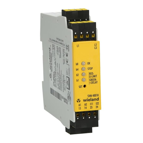
Wieland SVM 4001K-A User manual

Doc. # BA000926 – 02/2017 (Rev. D) SVM 4001K-A / 4001K-C DE 1
Montageanleitung
(Original)
SVM 4001K-A / 4001K-C
Stillstandswächter für 1- und 3-Phasen-Motoren ohne Sensorik
Geräteausführungen
SVM 4001K-A DC 24 V
R1.188.4020.0
mit Schraubklemme, steck-
bar
SVM 4001K-C DC 24 V
R1.188.4030.0
mit Federkraftklemme,
steckbar
Bestimmungsgemäße Verwendung
Das Gerät erfüllt die Anforderungen der Prüfgrundlagen
Kategorie 4 / PL e nach EN ISO 13849-1:2008 + AC:2009
SIL CL 3 nach EN 62061:2005 + AC:2010 +
A1:2013
SIL3 nach EN 61508 Parts 1- 7:2010
und kann in Anwendungen bis Kategorie 4 / PL e nach EN ISO
13849-1 und SIL 3 nach EN 62061 / EN 61508 eingesetzt wer-
den.
Die vorgesehene Anwendung ist die Überwachung von Bear-
beitungsmaschinen deren Antriebseinheiten keine Sensorik zur
Bewegungserkennung besitzen.
Mit einsetzender Bewegung der Antriebe oder bei erkannten
Fehlern wechseln die Relais des Stillstandswächters in die Ru-
helage.
Die Relaiskontakte sind als Schließer ausgeführt und potenzial-
frei an den Ausgangsklemmen verfügbar. Sie sind so zu ver-
wenden, dass die vorgesehene Schutzfunktion (Verriegelung
von Schutzeinrichtungen, Auslösung von Not-Halt usw.) ausge-
führt wird.
Der Stillstandswächter SVM 4001K kann in Sicherheitsstrom-
kreisen nach VDE 0113 T.1 eingesetzt werden und ist zur Mon-
tage auf einer 35mm-Normschiene vorgesehen.
Je nach äußerer Beschaltung ist maximal die Kategorie 4 / PL e
nach EN ISO 13849-1 bzw. SIL 3 nach EN 61508 zu erreichen.
WICHTIGER HINWEIS
Das hier beschriebene Produkt wurde entwickelt, um als Teil
eines Gesamtsystems sicherheitsgerichtete Funktionen zu
übernehmen.
Das Gesamtsystem wird durch Sensoren, Auswerte- und Mel-
deeinheiten sowie Konzepte für sichere Abschaltungen gebil-
det. Es liegt im Verantwortungsbereich des Herstellers einer
Anlage oder Maschine die korrekte Gesamtfunktion sicherzu-
stellen.
Der Hersteller der Anlage/Maschine ist verpflichtet, die Wirk-
samkeit des implementierten Sicherheitskonzepts innerhalb
des Gesamtsystems zu prüfen und nachzuweisen. Dieser
Nachweis ist nach jeglicher Modifikation am Sicherheitskon-
zept bzw. Sicherheitsparametern erneut zu erbringen. Firma
Wieland Electric ist nicht in der Lage, alle Eigenschaften eines
Gesamtsystems, das nicht durch Wieland Electric konzipiert
wurde, zu garantieren. Wieland Electric übernimmt auch keine
Haftung für Empfehlungen, die durch die nachfolgende Be-
schreibung gegeben bzw. impliziert werden. Auf Grund der
nachfolgenden Beschreibung können keine neuen, über die
allgemeinen Lieferbedingungen von Wieland Electric hinaus-
gehenden Garantie-, Gewährleistungs- oder Haftungsansprü-
che abgeleitet werden.

Doc. # BA000926 – 02/2017 (Rev. D) SVM 4001K-A / 4001K-C DE 2
Montageanleitung
(Original)
SVM 4001K-A / 4001K-C
Stillstandswächter für 1- und 3-Phasen-Motoren ohne Sensorik
SICHERHEITSBESTIMMUNGEN
•
Das Gerät darf nur von einer Elektrofachkraft oder unterwie-
senen Personen installiert und in Betrieb genommen wer-
den, die mit dieser Betriebsanleitung und den geltenden
Vorschriften über Arbeitssicherheit und Unfallverhütung ver-
traut sind. Beachten Sie die VDE- sowie die örtlichen Vor-
schriften, insbesondere hinsichtlich der Schutzmaßnahmen.
•Halten Sie beim Transport, der Lagerung und im Betrieb die
Bedingungen nach EN 60068-2-6, 04/95 ein. siehe techni-
sche Daten.
•Durch eigenmächtige Umbauten erlischt jegliche Gewähr-
leistung.
•Montieren Sie das Gerät in einen Schaltschrank; Staub und
Feuchtigkeit können sonst zu Beeinträchtigungen der Funk-
tionen führen.
•Sorgen Sie an allen Ausgangskontakten bei kapazitiven und
induktiven Lasten für eine ausreichende Schutzbeschaltung.
•Das Gerät ist unter besonderer Berücksichtigung der gefor-
derten Abstände nach DIN EN 50274, VDE 0660-514 einzu-
bauen.
•Während des Betriebes stehen Schaltgeräte unter gefährli-
cher Spannung. Schutzabdeckungen dürfen während des
Betriebes nicht entfernt werden.
•Wechseln Sie das Gerät nach dem ersten Fehlerfall unbe-
dingt aus!
•Entsorgen Sie das Gerät nach Ablauf seiner Lebensdauer
sachgerecht!
•Bewahren Sie diese Produktinformation auf!
•Bei Nichteinhaltung der Sicherheitsbestimmungen oder bei
unsachgemäßer Anwendung übernimmt die Firma Wieland
Electric GmbH keinerlei Haftung für daraus entstehende
Schäden an Personen oder Sachgegenständen
Blockschaltbild
Gerätebeschreibung
Die Eingangsklemmen L1, L2 und L3 müssen ständig direkt mit
dem zu überwachenden Antrieb verbunden sein. Schaltkon-
takte dürfen diese Verbindung auch bei abgeschaltetem Motor
nicht unterbrechen. Zwischen den Klemmen L1, L2 und L3 und
allen anderen Klemmen besteht eine 4 kV Potenzialtrennung.
Die Ausgangskontakte an den Klemmen 13-14 und 23-24 sind
sichere redundante Schließerkontakte mit Stopp Kategorie 0
nach EN 60204-1. Die Kontakte können zweikanalig parallel o-
der in Serie sicherheitsgerichtet verwendet werden.
Bild 1a:
Dreieckschaltung
3-Phasen-Motor
Bild 1b:
Sternschaltung
3-Phasen-Motor
Bild 1c: Stern-
Dreieckschaltung
3-Phasen-Motor
Bild 1d:
Anschluss
1-Phasen-Motor

Doc. # BA000926 – 02/2017 (Rev. D) SVM 4001K-A / 4001K-C DE 3
Montageanleitung
(Original)
SVM 4001K-A / 4001K-C
Stillstandswächter für 1- und 3-Phasen-Motoren ohne Sensorik
Initialisierung
Nach Anlegen der Betriebsspannung an die Klemmen A1 und A2
erfolgt zunächst ein Eigentest. Währenddessen bleiben die Re-
laiskontakte in Ruhestellung und die LED OK leuchtet rot (Bild
2a).
Nach fehlerfreiem Abschluss, sichtbar durch den Farbwechsel
der LED OK zu grün, ist das Gerät betriebsbereit (Bild 2b).
b8
b2
b1
b4
b8
b2
b1
b4
OK
Stop
OK
Stop
P1
P2
P1
P2
b8
b4
b2
b1
OK
Stop
P1
P2
b8
b4
b2
b1
OK
Stop
P1
P2
Bild 2a
Bild 2b
Bild 2c
Bild 2d
Initialisierung
Stillstand
Bewegung
Auslauf
Überwachungsbetrieb
Die Stillstand Erkennung erfolgt durch Auswertung der bei Aus-
lauf in der Motorwicklung induzierten Spannung (EMK). Über-
schreitet die Spannung an den Motorklemmen die eingestellte
Schwellenspannung, öffnen die Relaiskontakte unverzögert und
die LED STOP erlischt (Bild 2c). Unterschreitet während des
Motorauslaufs die EMK die Stillstand Schwelle, beginnt der Ab-
lauf der ebenfalls ein-stellbaren Einschaltverzögerung und die
LED STOP beginnt grün zu blinken (Bild 2d). Nach Ablauf der
Verzögerungszeit werden die Ausgangsrelais für Stillstand ein-
geschaltet und die LED STOP leuchtet grün (Bild 2b.)
Funktion der Steuereingänge I11 und I22
Tabelle 1: Einstellung der Betriebsarten
I11
I22
Funktionsart
Bedeutung
Durch 2-kanalige Beschaltung der
0 V
0 V
FA1
Relaiskontakte nur bei Stillstand geschlossen
Steuereingänge I11 und I22 kann die 24 V 0 V Nicht er-
laubt!
Stillstandsüberwachung ausgeblendet wer-
den.
0 V 24 V Nicht er-
laubt!
24 V 24 V FA2 Relaiskontakte bleiben auch bei Bewegung geschlos-
sen
Schaltschwelle Einstellung
Die Taste SET ca. 3 s betätigt halten, bis alle LED rot blinken.
Nach Loslassen der Taste blinken die LED entsprechend der Bi-
närkombination der aktuellen Parameterstufe. (siehe Tabelle 2).
Mit jeder kurzen Betätigung der SET Taste wird die nächsthö-
here Stufe zugewiesen. Durch längeres Betätigen der SET Taste
(ca. 2 s) wird der neu Wert dauerhaft im Gerät gespeichert und
der Einstellmodus verlassen.
Tabelle 2
Position
1
2
3
4
5
6
7
8
9
10
11
12
13
14
15
Werteinstellung
LED: b8 / OK
LED: b4 / STOP
b2
b1
Kontakte aktiv
[mV]
50
55
60
65
70
75
80
200
230
250
300
350
400
460
500
Kontakte offen
[mV]
120
120
120
120
120
120
120
1000
1000
1000
1000
1000
1000
1000
1000
Anzugsverzögerung Einstellung für Ausgangskontakte
Die Taste SET ca. 6 s betätigt halten, bis alle LED grün blinken.
Nach Loslassen der Taste blinken die LED entsprechend der ak-
tuellen Parameterstufe (siehe Tabelle 3). Mit jeder kurzen Betä-
tigung der SET Taste wird die nächsthöhere Stufe zugewiesen.
Durch längeres Betätigen der SET Taste (ca. 2 s) wird der neu
eingestellte Wert dauerhaft im Gerät gespeichert.
Tabelle 3
Position
1
2
3
4
5
6
7
8
9
10
11
12
13
14
15
Zeiteinstellung LED: b8 / OK
LED: b4/STOP
b2
b1
Anzugsverzöge-
rung [s] 0,5 1 2 3 4 5 6 7 8 10 12 14 16 18 20

Doc. # BA000926 – 02/2017 (Rev. D) SVM 4001K-A / 4001K-C DE 4
Montageanleitung
(Original)
SVM 4001K-A / 4001K-C
Stillstandswächter für 1- und 3-Phasen-Motoren ohne Sensorik
Sicherheitsfunktion während der Parametereinstellung
•Während des aktiven Einstellmodus sind im Hintergrund die
Sicherheitsfunktion und die Fehlerüberwachung weiter aktiv.
•Wird im aktiven Einstellmodus die Betriebsspannung unter-
brochen oder erfolgt für mehr als 20 s keine Tastenbetäti-
gung, wird der Modus ohne Speicherung beendet.
•Die bisherigen Parameter bleiben prozesswirksam.
•Die Parameter-Neueinstellung geht verloren.
•Parameteränderungen werden erst nach Speicherung pro-
zesswirksam.
Fehlerüberwachung
•Während des Betriebs des Stillstandswächters erfolgt eine
laufende Überwachung auf in- und externe Fehler. LED b8
blinkt rot (Bild 4) wenn:
−Drahtbruch im Messkreis
−Inkonsistente Signale auf den einzelnen Phasen
−Ungültige Klemmenbeschaltung der Funktionsein-
gänge I11/I22
−Betriebsspannung außerhalb des Toleranzbereichs
−Interne Gerätefehler
•Die Überwachung ist immer aktiv. (abgeschaltete Stillstand-
serkennung)
•Im Fehlerfall sind die Ausgangskontakte abgeschaltet.
Fehleranzeige
Bild 4
b8
b2
b1
b4
OK
Stop
P1
P2
•Erkannte Fehler werden gespeichert und
die Ausgangskontakte wechseln unverzö-
gert in Ruhestellung.
Fehlerbehebung
•Nach Behebung externer Fehler wird der
Fehlerspeicher automatisch gelöscht.
•Zur Behebung interner Fehler muss das
Gerät zur Überprüfung an Wieland Electric
zurückgesandt werden.
B8
1
1
1
1
1
Interner Gerätefehler
B8
1
2
1
2
1
2
1
2
Unzulässige Betriebspannung
B8
1
2
3
1
2
3
1
2
3
Drahtbruch an Sensorleitung
B8
1
2
3
4
1
2
3
4
1
Einkanaliges Signal
B8
1
2
3
4
5
1
2
3
4
5
Relaisfehler
Diagramm 3a
Diagramm 3b
Überwachung der Schutzhaube
(Diagramm 3a)
Bei eingestellter Funktionsart FA1 ist die Überwachung stän-
dig aktiv. Die Schutzeinrichtung wird nur bei erkanntem Still-
stand entriegelt.
1) Not-Halt
2) Bearbeitungsanlage
3) Schutzhaube
4) Haube auf/ zu
5) Werkzeug
6) Motoreinspeisung
7) Motor
8) EMK-Sensorleitung
9) Schutzhaubenschalter
10) Schutzhaubenfreigabe
Stillstandsüberwachung (Diagramm 3b)
Bei Anschluss der Steuereingänge I11 und I22 an die Meldesig-
nale von Schutzeinrichtungen ist bei geschlossener Schutzein-
richtung die Bewegungserkennung deaktiviert. Die Relaiskon-
takte sind dauerhaft geschlossen und die LED STOP leuchtet
grün.
Ein Öffnen der Schutzhaube bewirkt den Wechsel zu Funktionsart
FA1 und löst bei anlaufendem Motor die Not-Halt Funktion aus.

Doc. # BA000926 – 02/2017 (Rev. D) SVM 4001K-A / 4001K-C DE 5
Montageanleitung
(Original)
SVM 4001K-A / 4001K-C
Stillstandswächter für 1- und 3-Phasen-Motoren ohne Sensorik
Hinweis:
Der Anwender muss durch die Einstellung der Schaltschwelle
(EMF-Limit ) und der Anzugsverzögerungszeit (T) sicherstellen,
dass die Relais K1 und K2 erst bei Stillstand des Antriebes ein-
schalten!
Prinzipieller Abschaltvorgang
Kontakt Lebensdauer
Schaltspiele
Schaltstrom (A)
Technische Daten
Eingangsdaten
Betriebsspannung
24 V DC –15 +10 %
Stromaufnahme bei UN bei Stillstand
150 mA , bei Bewegung: 80 mA
Maximale Spannung an L1, L2, L3
690 V AC
Maximale Stromaufnahme/ Frequenz
L1, L2, L3 bei 690V AC
jeweils 0,35 mA / 5 kHz
Ausgangsdaten
Minimaler Schaltstrom der Kontakte
10 mA
Maximaler Schaltstrom der Kontakte
8 A
Schaltvermögen / Schaltspiele
IEC/EN 60947-4-1
AC1: 230 V / 8 A, 100 000
DC1: 24 V / 8 A, 100 000
IEC/EN 60947-5-1
AC15: 230 V/3 A, DC13:
24 V / 4 A
Mechanische Lebensdauer
> 20 x 106 Schaltspiele
Kontaktwerkstoff
AgNi10
Kontaktabsicherung
5 A träge
Maximale Schaltspiele bei AC15/DC13
360 Zyklen/h
Bemessungsisolationsspannung
250 V AC
Stoßspannungsfestigkeit
4 kV, Verschmutzungsgrad 2
Ansprechzeit
Typisch 20 ms
Rückfallzeit
Typisch 20 ms
Umgebungsdaten
Umgebungstemperatur
-20 bis +55°C
DIN IEC 60068-2-3
Lagertemperatur
-40 bis +70°C
DIN IEC 60068-2-3
Rüttelfestigkeit in allen 3 Ebenen
Sinus 10–55 Hz, 0,35 mm, 10 Zyklen,1 Oktave / min
Einschaltdauer
100 %
Luft- und Kriechstrecken
DIN EN 50178,
sichere Trennung
Mindestschutzart
IP 54 Nur für den Einbau im Schaltschrank
Gehäusematerial
PC Makrolon
Allgemeine Daten
10
Schaltspiele / Cycles
Schaltstrom (A) / Switching current (A)
DC13
24V
AC15
230V
AC1
230V
DC1
24V
7
10
6
10
5
10
4
0.1 0.5 1.0 2.0 3.0 4.0 5610

Doc. # BA000926 – 02/2017 (Rev. D) SVM 4001K-A / 4001K-C DE 6
Montageanleitung
(Original)
SVM 4001K-A / 4001K-C
Stillstandswächter für 1- und 3-Phasen-Motoren ohne Sensorik
Klemmen- und Anschlussdaten
Schraubklemmen
Federkraftklemmen (TWIN)
Eindrähtig oder feindrähtig
1 × 0,2 – 2,5 mm²
2 × 0,2 – 1,0 mm²
1 × 0,2 – 1,5 mm²
Feindrähtig mit Aderendhülse
1 × 0,25 – 2,5 mm²
2 × 0,25 – 1,0 mm²
1 × 0,25 – 1,5 mm²
AWG
26 – 14
24 – 16
Maximales Anzugsdrehmoment
0,5–0,6 Nm (5–7 lbf-in)
—
Abisolierlänge
7 mm
7 mm
Jahr: 260 Tage
Schaltspannung 24 V DC
Kontakt Lebensdauer
Tag: 8 h
Last
DC1
DC13
Jahr
Schaltstrom
1 A
1 A
Schaltspiele
769
91
5
384
45
10
192
23
20
AC1: nicht induktiver Last / 250 V AC
AC15: elektromagnetischer Last / 230 V AC
DC1: nicht induktiver Last / 24 V DC
DC13: elektromagnetischer Last / 24 V DC
Montage, Demontage
Montage
Demontage
1
3
Gerät auf die Hutschiene
einhängen.
Gerät in Pfeilrichtung her-
unterdrücken.
2
4
Durch leichten Druck in
Pfeilrichtung Gerät auf die
Hutschiene aufschnap-
pen.
Im heruntergedrückten
Zustand Gerät in Pfeilrich-
tung aus der Verrastung
lösen und von der Hut-
schiene nehmen.
Abmessungen
SVM 4001K-A DC 24 V
SVM 4001K-C DC 24 V

Doc. # BA000926 – 02/2017 (Rev. D) SVM 4001K-A / 4001K-C DE 7
Montageanleitung
(Original)
SVM 4001K-A / 4001K-C
Stillstandswächter für 1- und 3-Phasen-Motoren ohne Sensorik

Doc. # BA000926 – 02/2017 (Rev. D) SVM 4001K-A / 4001K-C EN 8
Installation instructions
(translation from original)
SVM 4001K-A / 4001K-C
Standstill monitoring for 1- and 3-phases motor without sensor
system
Device versions
SVM 4001K-A DC 24 V
R1.188.4020.0
with screw terminals,
plug-in
SVM 4001K-C DC 24 V
R1.188.4030.0
with spring-loaded termi-
nals, plug-in
Proper use
The equipment fulfills the requirements of the test principles
Category 4 / PL e according to EN ISO 13849-1:2008 + AC:2009
SIL CL 3 according to EN 62061:2005 + AC:2010 +
A1:2013
SIL3 according to EN 61508 Parts 1- 7:2010
and can be used in applications till category 4 / PL e according
to EN ISO 13849-1 and SIL 3 according to EN 62061 / EN
61508.
Drives of machine tools without movement sensor systems can
be monitored with standstill monitoring SMV 4001K.
The output contacts of the equipment open, if the drive moves
or there is a failure in the system.
The output contacts are potential-free NO contacts. They can
be used to lock a safety cover or for an emergency stop func-
tion.
The standstill monitoring SVM 4001K can be used in safety
function circuit according to VDE 0113 T1. It can be mounted
at a 35mm DIN rail.
In dependence of the external circuit maximal category 4 / PL e
can be arrived according to EN ISO 13849-1 respectively SIL 3
according to EN 61508.
IMPORTANT NOTICE
The described product has been developed as a part of a
safety system.
The system includes sensors, evaluation units, control units
and a concept for safe switch-off. The manufacturer is in
charge to ensure the correct functionality of the entire system.
The manufacturer is in charge to check and to prove the effec-
tiveness of the safety concept.
Any modification at the safety parameters or the safety con-
cept itself requires to re-prove the effectiveness of the safety
concept.
Wieland Electric cannot guarantee properties of systems that
not have been established in their own responsibility.
Wieland Electric also does not accept liability for any recom-
mendations derived from the following description. Claims
that go beyond the rights cited in the warranty are excluded.

Doc. # BA000926 – 02/2017 (Rev. D) SVM 4001K-A / 4001K-C EN 9
Installation instructions
(translation from original)
SVM 4001K-A / 4001K-C
Standstill monitoring for 1- and 3-phases motor without sensor
system
SAFETY REGULATIONS
•The unit may only be installed and operated by those who
are qualified electrical engineers or have received sufficient
training and are familiar with both these instructions and the
current regulations for safety at work and accident preven-
tion. Follow VDE, EN as well as local regulations especially
as regards preventative measures!
•Ignoring the safety regulations can lead to death, serious in-
jury or cause considerable damage! Transport, storage and
operating conditions should all conform to EN 60068-2-1, 2-
2. See technical details.
•Any guarantee is void following unauthorised modifications.
This can lead to death, serious injury or cause considerable
damage!
•The unit should be mounted in a cabinet otherwise damp-
ness or dust could lead to functional impairment.
•Adequate fuse protection must be provided on all output
contacts especially with capacitive and inductive loads.
•The unit must be installed following the specification of DIN
EN 50274, VDE 0660-514 regarding the required distances.
•During operation, parts of the electronic switchgear carry
high voltage.
•DANGER! During operation the protective covers must not
be removed from the electronic switchgear!
•The device must always be replaced after the first malfunc-
tion!
•The unit must be disposed of properly when it reaches the
end of it service life.
•Keep the operating instructions!
Diagram
Equipment description
The input terminals L1, L2 and L3 have to be always directly
connected to the power supply terminals of the monitored
drive. No switching contacts are allowed between L1, L2, L3
and the terminals of the drive.There is a 4 kV electrical isolation
between L1, l2, L3 and all other terminals of SVM 4001K. The
output contacts at the terminals 13-14 and 23-24 are safe re-
dundant NO contacts stop category 0 according to EN 60204-1.
The contacts can be used as two-channel (parallel) or serial
safety circuit.
Diagram 1a:
Delta-connection
3-phases motor
Diagram 1b:
Star connection
3-phases motor
Diagram 1c: Star
delta-connection
3-phases motor
Diagram 1d:
connection
1-phases motor

Doc. # BA000926 – 02/2017 (Rev. D) SVM 4001K-A / 4001K-C EN 10
Installation instructions
(translation from original)
SVM 4001K-A / 4001K-C
Standstill monitoring for 1- and 3-phases motor without sensor
system
Display
After the connection of the power supply to the terminals A1 and
A2 an internal test is started. During this test the output contacts
are open and the LED
OK
is illuminated red (picture 2a).
The unit is ready after a faultless test displayed via the green illu-
minated LED OK (picture 2b).
b8
b2
b1
b4
b8
b2
b1
b4
OK
Stop
OK
Stop
P1
P2
P1
P2
b8
b4
b2
b1
OK
Stop
P1
P2
b8
b4
b2
b1
OK
Stop
P1
P2
Picture 2a
Picture 2b
Picture 2c
Picture 2d
Display Standstill Movement Run-out
Monitored function
The detection of standstill happens via the measurement of the
electromotive force (EMF) after the running-out of the drive.
The output contacts open immediately, if the EMF value at the
drive terminal is higher than the adjustable voltage value.
The LED STOP is not illuminated (picture 2c). At the end of the
adjustable time delay the output contacts close (NO contacts).
The LED STOP is illuminated green again (picture 2b).
Function of the control inputs I11 und I22
Table 1: Selection of the function modes
I11
I22
Function mode
Description
The standstill monitoring is inactive, if the
control inputs
0 V 0 V FA1 Output contacts are only closed during standstill
I11 and I22 are connected to 24V DC
24 V
0 V
Not allowed!
0 V
24 V
Not allowed!
24 V 24 V FA2 Output contacts are closed also during movement.
Switching value adjusting
The button SET has to be activated for approximately 3 s, till all
LED are flashing red. After the actuation of the button SET the
LED are flashing accordingly to the binary combination of the
actual parameters adjustment. The value of the
parameters increases one step after every short actuation of
the button SET. To memorize the new value permanently and
quit the adjusting mode the button has to be actuated nearly
2 s. The new parameters are active after the storage.
See table 2.
Table 2
Position
1
2
3
4
5
6
7
8
9
10
11
12
13
14
15
Value adjustment LED: b8 / OK
LED: b4 / STOP
b2
b1
Contacts on [mV] 50 55 60 65 70 75 80 200 230 250 300 350 400 460 500
Contacts out [mV] 120 120 120 120 120 120 120 1000 1000 1000
1000
1000 1000 1000
1000
ON-delay time of the output contacts
The button SET has to be activated for approximately 6 s, till all
LED are flashing green. After the actuation of the button SET
the LED are flashing accordingly to the binary combination of
the actual parameters adjustment.The value of the parameters
increases one step after every short actuation of the button
SET. To memorize the new value permanently and quit the ad-
justing mode the button has to be actuated nearly 2 s. The new
parameters are active after the storage. See table 3
Table 3
Position
1
2
3
4
5
6
7
8
9
10
11
12
13
14
15
Time adjustment LED: b8 / OK
LED: b4/STOP
b2
b1
Time delay [s] 0,5 1 2 3 4 5 6 7 8 10 12 14 16 18 20

Doc. # BA000926 – 02/2017 (Rev. D) SVM 4001K-A / 4001K-C EN 11
Installation instructions
(translation from original)
SVM 4001K-A / 4001K-C
Standstill monitoring for 1- and 3-phases motor without sensor
system
Safety function during the adjustment
•The new parameters adjustment will be not memorized, if the power supply was turn-off during the adjustment or no actuation
of the SET button has happened longer than 20s.
•The old adjustment remains process active.
•The safety function and the faults monitoring are also active during the adjustment mode.
Faults monitoring
•During the function mode of SVM 4001K following external
and internal faults are monitored. LED b8 flashes red (pic-
ture 4) if:
−Wire breakage in the measurement circuit.
−Inconsistent signals at the single phases.
−Not allowed connection of the control inputs I11/I22
−Power supply out of the tolerance range
−Internal unit faults
•The faults monitoring is always active. (Inactive standstill
monitoring).
•The output contacts are open if there is a fault.
Faults dis-
play
Picture 4
b8
b2
b1
b4
OK
Stop
P1
P2
•
SMV 4001K storages all detected faults and the
output contacts open immediately.
Faults quit
•After elimination of external faults the failure
memory will be automatically cleared.
•If there were internal faults the unit has to be re-
turned to the manufacturer.
B8
1
1
1
1
1
Internal unit faults
B8
1
2
1
2
1
2
1
2
Illegal power supply
B8
1
2
3
1
2
3
1
2
3
Wire break sensor input
B8
1
2
3
4
1
2
3
4
1
One channel signal
B8
1
2
3
4
5
1
2
3
4
5
Relay fault
Diagram 3a
Diagram 3b
Safety cover monitoring
(Diagram 3a)
The monitoring is permanently active during the function
mode FA1. The safety cover is only unlocked, if the drive is in
standstill
1) emergency stop
2) process unit
3) safety cover
4) cover open/ closed
5) tool
6) drive power supply
7) drive
8) EMF-Sensor wire
9) safety cover switch
10) safety cover enabling
Standstill monitoring
(Diagram 3b)
The standstill monitoring is inactive, if the control inputs I11 and
I22 are connected to 24 V DC via the safety cover switch and the
safety cover is closed. The output contacts are permanently
closed. The LED STOP illuminates green.
The standstill monitoring is active, if the safety cover is opened.
Function mode FA1 is selected. An emergency stop function will
be happened, if the drive moves.

Doc. # BA000926 – 02/2017 (Rev. D) SVM 4001K-A / 4001K-C EN 12
Installation instructions
(translation from original)
SVM 4001K-A / 4001K-C
Standstill monitoring for 1- and 3-phases motor without sensor
system
Operation Note:
The user must set the switching threshold (EMF limit) and the
ON delay time (T) to ensure that the relays K1 and K2 switch
only at the standstill of the motor.
Contact durability
Cycles
Switching Current (A)
principle shutdown
Technical Data
Input data
Power supply
24 V DC –15 +10 %
Current drain at UN
150 mA
Maximal voltage at L1, L2, L3
690 V AC
Maximal current drain/ Frequency
L1, L2, L3 with 690 V AC
0,35 mA / 5 kHz
Output data
Minimal switching current: contacts
10 mA
Maximal switching current: contacts
8 A
Switching capacity, switching cycles
IEC/EN 60947-4-1
AC1: 230 V / 8 A, 100 000
DC1: 24 V / 8 A, 100 000
IEC/EN 60947-5-1
AC15: 230 V / 3 A,
DC13: 24 V / 4 A
Mechanical life switching cycles
> 20 x 106
Contact material
AgNi10
Contact fusing
5 A slow
Maximal switching cycles AC15/ DC13
360 / h at max. switching current AC15 / DC13
Rated insulation voltage
250 V AC
Impulse withstand voltage
4 kV, pollution degree 2
Typical reaction time
20 ms
Typical dropout time
20 ms
Environment data
Environment temperature
-20 to +55°C
DIN IEC 60068-2-3
Storage temperature
-40 to +70°C
DIN IEC 60068-2-3
Vibration resistance 3 axis
Sinus 10–55 Hz, 0,35 mm, 10 cycles, 1 octave / min
Duty cycle
100 %
Air and creep age distance
DIN EN 50178,
safe isolation
Protection class
installation in a closed cabinet only with min. IP 54
Housing material
PC Makrolon
10
Schaltspiele / Cycles
Schaltstrom (A) / Switching current (A)
DC13
24V
AC15
230V
AC1
230V
DC1
24V
7
10
6
10
5
10
4
0.1 0.5 1.0 2.0 3.0 4.0 5610

Doc. # BA000926 – 02/2017 (Rev. D) SVM 4001K-A / 4001K-C EN 13
Installation instructions
(translation from original)
SVM 4001K-A / 4001K-C
Standstill monitoring for 1- and 3-phases motor without sensor
system
General data
Terminals and connection
screw-type terminals
spring-type terminals
Single-core or finely stranded
1 × 0,2 – 2,5 mm²
2 × 0,2 – 1,0 mm²
2 × 0,2 – 1,5 mm²
Finely stranded with wire-end ferrule ac-
cording to DIN 46228
1 × 0,25 – 2,5 mm²
2 × 0,25 – 1,0 mm²
2 × 0,25 – 1,5 mm²
AWG
26 – 14
24 – 16
Maximum tightening torque
0,5 – 0,6 Nm (5 – 7 lbf-in)
—
Stripping length
7 mm
7 mm
Year: 260 days
Switching voltage 24 V DC
Contact durability
Day: 8 h
Load
DC1
DC13
Year
Switching current
1 A
1 A
Cycles
769
91
5
384
45
10
192
23
20
AC1: non inductive load / 250 V AC
AC15: electro magnetically load / 230 V AC
DC1: non inductive load / 24 V DC
DC13: electro magnetically load / 24 V DC
Assembly, Disassembly
Assembly
Disassembly
1
3
Attach device to DIN rail.
Push device down (in direction
of arrow).
2
4
Press the device carefully
onto the DIN rail (in direc-
tion of arrow) until it locks
into place.
Release device and remove it
from the DIN rail (see arrow).
Dimension Diagram
SVM 4001K-A DC 24 V
SVM 4001K-C DC 24 V

Doc. # BA000926 – 02/2017 (Rev. D) SVM 4001K-A / 4001K-C EN 14
Installation instructions
(translation from original)
SVM 4001K-A / 4001K-C
Standstill monitoring for 1- and 3-phases motor without sensor
system

Doc. # BA000926 – 02/2017 (Rev. D) SVM 4001K-A / 4001K-C FR 15
Mode d’emploi
(traduction de la notice originale)
SVM 4001K-A/4001K-C
Détecteur d’arrêt pour moteurs mono et triphasés sans aucun
capteur
Versions des appareils
SVM 4001K-A 24 V CC
R1.188.4020.0
avec borne à vis, enfichable
SVM 4001K-C 24 V CC
R1.188.4030.0
avec borne à ressort, enfi-
chable
Utilisation conforme à l’usage prévu
L’appareil répond aux exigences des normes suivantes régis-
sant les essais :
Catégorie 4/PL e selon les normes EN ISO 13849-1:2008 +
AC:2009
SIL CL 3 selon la norme EN 62061:2005 +
AC:2010 + A1:2013
SIL3 selon la norme EN 61508:2010, parties 1
à 7
et peut être utilisé dans des applications atteignant la catégo-
rie 4/PL e selon la norme EN ISO 13849-1 et SIL 3 selon les
normes EN 62061/EN 61508.
Selon l’usage prévu, l’appareil doit servir à la surveillance de
machines d’usinage dont les unités d’entraînement ne dispo-
sent d’aucun capteur assurant la détection des mouvements.
En cas de mouvement provoqué par les entraînements ou d’er-
reurs identifiées, les relais du détecteur d’arrêt passent en posi-
tion de repos.
Les contacts de relais sont conçus comme des contacts à fer-
meture. Exempts de potentiel, ils sont disponibles sur les
bornes de sortie. Ils doivent être utilisés de façon à mettre en
œuvre la fonction de protection prévue (verrouillage des dispo-
sitifs de protection, déclenchement de l’arrêt d’urgence, etc.).
Le détecteur d’arrêt SVM 4001K peut s’installer sur des circuits
de sécurité conformes à la norme VDE 0113, partie 1. Il a été
conçu pour être monté sur un rail normalisé de 35 mm.
Selon le branchement extérieur, il est possible d’atteindre au
maximum la catégorie 4/PL e selon la norme EN ISO 13849-1
ou SIL 3 selon la norme EN 61508.
REMARQUE IMPORTANTE
Le produit décrit présentement a été conçu dans le but de
remplir des fonctions de sécurité, en tant que composant d’un
système global.
Ce système global est formé de capteurs, d’unités d’interpré-
tation et de signalisation, ainsi que de concepts pour des cou-
pures sécurisées. Il est de la responsabilité du constructeur de
l’installation ou de la machine de garantir son bon fonctionne-
ment.
Le constructeur de l’installation ou de la machine s’engage à
vérifier et prouver l’efficacité du concept de sécurité mis en
œuvre au sein du système global. Il convient d’apporter une
nouvelle fois cette preuve après la moindre modification du
concept ou des paramètres de sécurité. La société Wieland
Electric n’est pas en mesure de garantir toutes les caractéris-
tiques d’un système global conçu par des tiers. Wieland Elec-
tric décline toute responsabilité concernant les recommanda-
tions fournies dans la description ci-après, qu’elles soient ex-
plicites ou implicites. Aucun nouveau droit de recours en ga-
rantie ou responsabilité, dépassant le cadre des conditions gé-
nérales de livraison de Wieland Electric, ne pourra être conféré
sur la base de la description suivante.

Doc. # BA000926 – 02/2017 (Rev. D) SVM 4001K-A / 4001K-C FR 16
Mode d’emploi
(traduction de la notice originale)
SVM 4001K-A/4001K-C
Détecteur d’arrêt pour moteurs mono et triphasés sans aucun
capteur
CONSIGNES DE SÉCURITÉ
•
Seuls des électriciens qualifiés ou des personnes dûment for-
mées, familiarisés avec ce mode d’emploi et les prescriptions
en vigueur en matière de sécurité du travail et de prévention
des accidents, sont autorisés à installer et à mettre en service
l’appareil. Il convient de respecter les prescriptions VDE, ainsi
que toutes les prescriptions locales, notamment en ce qui con-
cerne les mesures de protection.
•Lors du transport, du stockage et de la mise en service, res-
pecter les conditions décrites dans la norme EN 60068-2-6
d’avril 1995 (voir « Caractéristiques techniques »).
•Toute modification non autorisée sur l’appareil fait perdre le
bénéfice de la garantie.
•
Monter l’appareil dans une armoire électrique, afin d’éviter que
la poussière et l’humidité puissent l’endommager.
•En cas de charges capacitives et inductives, assurer un bran-
chement de protection suffisant au niveau de tous les contacts
de sortie.
•L’appareil doit être monté en tenant compte des distances exi-
gées dans les normes DIN EN 50274 et VDE 0660-514.
•En cours de service, les mécanismes de connexion impliquent
la présence de tensions dangereuses. Les couvercles de pro-
tection ne doivent donc pas être retirés.
•Remplacer impérativement l’appareil à la première défaillance.
•Éliminer l’appareil de façon appropriée au terme de sa durée
de vie.
•Conserver les présentes informations sur le produit.
•En cas de non-respect des consignes de sécurité ou d’utilisa-
tion non conforme, la société Wieland Electric GmbH décline
toute responsabilité quant aux dommages corporels ou maté-
riels susceptibles d’en résulter.
Schéma de connexion du bloc
Description de l’appareil
Les bornes d’entrée L1, L2 et L3 doivent être connectées direc-
tement et en permanence à l’entraînement à surveiller. Les con-
tacts de commutation ne doivent pas interrompre cette con-
nexion, même si le moteur est arrêté. Une isolation galvanique
de 4 kV sépare les bornes L1, L2 et L3 de toutes les autres
bornes. Les contacts de sortie sur les bornes 13-14 et 23-24
sont des contacts à fermeture redondants et sécurisés de caté-
gorie d’arrêt 0, conformément à la norme EN 60204-1. Ces
contacts peuvent être utilisés en toute sécurité soit en parallèle
sur deux canaux, soit en série.
Figure 1a :
connexion en
triangle
du moteur tri-
phasé
Figure 1b :
connexion en
étoile
du moteur tri-
phasé
Figure 1c : con-
nexion en étoile-
triangle
du moteur tri-
phasé
Figure 1d :
raccordement
du moteur mo-
nophasé

Doc. # BA000926 – 02/2017 (Rev. D) SVM 4001K-A / 4001K-C FR 17
Mode d’emploi
(traduction de la notice originale)
SVM 4001K-A/4001K-C
Détecteur d’arrêt pour moteurs mono et triphasés sans aucun
capteur
Initialisation
Un autotest est effectué au niveau des bornes A1 et A2 suite à la
mise sous tension. Au cours de ce test, les contacts de relais res-
tent en position de repos et la LED OK s’allume en rouge (fi-
gure 2a).
Une fois le test terminé sans erreur, ce qui se traduit par le chan-
gement de couleur de la LED OK au vert, l’appareil est prêt à
fonctionner (figure 2b).
b8
b2
b1
b4
b8
b2
b1
b4
OK
Stop
OK
Stop
P1
P2
P1
P2
b8
b4
b2
b1
OK
Stop
P1
P2
b8
b4
b2
b1
OK
Stop
P1
P2
Figure 2a
Figure 2b
Figure 2c
Figure 2d
Initialisation
Arrêt
Mouvement
Décélération
Mode de surveillance
La détection de l’arrêt s’effectue par le biais de l’interprétation
de la tension induite en cas de ralentissement dans l’enroule-
ment du moteur (FEM). Si la tension au niveau des bornes du
moteur dépasse la tension de seuil définie, les contacts de re-
lais s’ouvrent instantanément et la LED STOP s’éteint (fi-
gure 2c). Si la FEM tombe en dessous du seuil d’arrêt durant le
ralentissement du moteur, le délai de temporisation au démar-
rage, qui est également réglable, commence à s’écouler et la
LED STOP se met à clignoter en vert (figure 2d). Après expira-
tion du délai de temporisation au démarrage, les relais de sortie
servant à l’arrêt sont activés et la LED STOP s’allume en vert (fi-
gure 2b.)
Fonction des entrées de commande I11 et I22
Tableau 1 – Réglage des modes de fonc-
tionnement I11 I22
Mode de
fonctionne-
ment
Signification
Grâce au branchement à 2 canaux
0 V
0 V
FA1
Contacts de relais fermés uniquement à l’arrêt
des entrées de commande I11 et I22, 24 V 0 V Interdit.
la surveillance de l’arrêt peut être masquée.
0 V
24 V
Interdit.
24 V 24 V FA2 Contacts de relais restant fermés même en cas de
mouvement
Réglage du seuil de commutation
Maintenir la touche SET enfoncée pendant près de 3 s jusqu’à
ce que toutes les LED clignotent en rouge. Dès que la touche
est relâchée, les LED clignotent en fonction de la combinaison
binaire du niveau actuel des paramètres (voir le tableau 2).
Chaque bref appui sur la touche SET assigne le niveau immé-
diatement supérieur. Il suffit d’actionner la touche SET plus lon-
guement (env. 2 s) pour enregistrer durablement la valeur dans
l’appareil et quitter le mode de réglage.
Tableau 2
Position
1
2
3
4
5
6
7
8
9
10
11
12
13
14
15
Réglage des va-
leurs
LED : b8/OK
LED : b4/STOP
b2
b1
Contacts actifs
[mV]
50
55
60
65
70
75
80
200
230
250
300
350
400
460
500
Contacts ouverts [mV] 120 120 120 120 120 120 120 1 000
1 000
1 00
0
1 00
0
1 00
0
1 00
0
1 00
0
1 00
0
Réglage de la temporisation à l’enclenchement des contacts de sortie
Maintenir la touche SET enfoncée pendant près de 6 s jusqu’à ce que toutes les LED clignotent en vert. Dès que la touche est relâ-
chée, les LED clignotent en fonction du niveau actuel des paramètres (voir le tableau 3). Chaque bref appui sur la touche SET as-
signe le niveau immédiatement supérieur. Il suffit d’actionner la touche SET plus longuement (env. 2 s) pour enregistrer durable-
ment la valeur dans l’appareil.
Tableau 3
Position
1
2
3
4
5
6
7
8
9
10
11
12
13
14
15
Réglage du délai LED : b8/OK
LED : b4/STOP
b2
b1
Temporisation à
l’enclenchement [s] 0,5 1 2 3 4 5 6 7 8 10 12 14 16 18 20

Doc. # BA000926 – 02/2017 (Rev. D) SVM 4001K-A / 4001K-C FR 18
Mode d’emploi
(traduction de la notice originale)
SVM 4001K-A/4001K-C
Détecteur d’arrêt pour moteurs mono et triphasés sans aucun
capteur
Fonction de sécurité durant le réglage des paramètres
La fonction de sécurité et la surveillance des erreurs restent actives à l’arrière-plan pendant toute la durée d’activation du mode de
réglage. Annulation du réglage des paramètres : si la tension est coupée alors que le mode de réglage est activé ou qu’une touche
est actionnée pendant plus de 20 secondes, ce mode est abandonné sans enregistrer les modifications effectuées. Le nouveau
réglage des paramètres est donc perdu et l’ancienne valeur des paramètres reste appliquée. Efficacité du réglage des paramètres :
les modifications des paramètres ne sont prises en compte qu’après leur enregistrement.
Surveillance des erreurs
•Durant le fonctionnement du détecteur d’arrêt, une surveil-
lance courante des erreurs internes et externes est exécu-
tée :
−Rupture de fil dans le circuit de mesure
−Signaux incohérents sur les différentes phases
−Branchement incorrect des bornes des entrées fonc-
tionnelles I11/I22
−Tension de service en dehors de la plage de tolérance
−Erreurs internes de l’appareil
•La surveillance est également active dans le type de fonc-
tionnement FA2. (Détection de l’arrêt désactivée)
Affichage des
erreurs
Figure 4
b8
b2
b1
b4
OK
Stop
P1
P2
•Les erreurs détectées sont enregistrées et les
contacts de sortie passent instantanément
en position de repos. La LED
OK
clignote en
rouge (figure 4).
Élimination des erreurs
•La mémorisation des erreurs est automati-
quement supprimée dès que les erreurs ex-
ternes sont éliminées.
•Pour éliminer des erreurs internes, l’appareil
doit être renvoyé à Wieland Electric à des
fins de contrôle.
B8
1
1
1
1
1
Erreure interne
B8
1
2
1
2
1
2
1
2
Tension de fonctionnement illicite
B8
1
2
3
1
2
3
1
2
3
Rupture de câble de capteur
B8
1
2
3
4
1
2
3
4
1
Signal monocanale
B8
1
2
3
4
5
1
2
3
4
5
Erreure du relais
Diagramme 3a
Diagramme 3b
Surveillance du capot de protection
(diagramme 3a)
La surveillance est active en permanence si le type de fonction-
nement FA1 est réglé. Le dispositif de protection n’est déver-
rouillé qu’en cas d’arrêt détecté.
1) Arrêt d’urgence
2) Installation d’usinage
3) Capot de protection
4) Capot ouvert/fermé
5) Outil
6) Injection moteur
7) Moteur
8) Circuit de capteur FEM
9) Commutateur du capot de
protection
10) Déverrouillage du capot
de protection
Surveillance de l’arrêt
(diagramme 3b)
Lorsque les entrées de commande I11 et I22 sont raccordées
aux signaux d’état des dispositifs de protection, la détection
des mouvements est désactivée dès qu’un dispositif de protec-
tion est fermé. Les contacts de relais sont fermés en continu et
la LED STOP s’allume en vert.
L’ouverture du capot de protection provoque le pa
ssage au type
de fonctionnement FA1 et déclenche la fonction d’arrêt d’ur-
gence si le moteur tourne.

Doc. # BA000926 – 02/2017 (Rev. D) SVM 4001K-A / 4001K-C FR 19
Mode d’emploi
(traduction de la notice originale)
SVM 4001K-A/4001K-C
Détecteur d’arrêt pour moteurs mono et triphasés sans aucun
capteur
Remarque:
L'utilisateur doit garantir, par le biais du réglage du seuil de
commutation (limite EMF) et de la temporisation de serrage (T),
que les relais K1 et K2 ne sont activés qu'à l'arrêt de l'entraîne-
ment!
Procédure de déactivation standard
Durée de vie des contacts
Cycles de commutation
Courant de commutation (A)
Caractéristiques techniques
Entrées
Tension de service
24 V CC –15 +10 %
Courant absorbé U
N
à l’arrêt
150 mA, en cas de mouvement : 80 mA
Tension maximale à L1, L2, L3
690 V CA
Courant absorbé/fréquence max.
L1, L2, L3 à 690 V CA
0,35 mA / 5 kHz chacun
Sorties
Courant de commutation minimal des contacts
10 mA
Courant de commutation maximal des contacts
8 A
Pouvoir de coupure/cycles de commutation
CEI/EN 60947-4-1
CA1 : 230 V/8 A, 100 000
CC1 : 24 V/8 A, 100 000
CEI/EN 60947-5-1
CA15 : 230 V/3 A, CC13 :
24 V / 4 A
Durée de vie mécanique
> 20 x 106 cycles de commutation
Matériau des contacts
AgNi10 (argent-nickel)
Fusible pour les contacts
5 A, temporisé
Cycles de commutation max. avec CA15/CC13
360 cycles/h
Tension nominale d’isolement
250 V CA
Tension de tenue aux chocs
4 kV, degré d’encrassement 2
Temps de réponse
20 ms (type)
Temps de relâchement
20 ms (type)
Environnement
Température ambiante
-20 à + 55°C
DIN CEI 60068-2-3
Température de stockage
-40 à + 70°C
DIN CEI 60068-2-3
Résistance aux vibrations aux 3 niveaux
Sinus 10 à 55 Hz, 0,35 mm, 10 cycles, 1 octave / min.
Durée d’enclenchement
100 %
Lignes de fuite et distances dans l’air
DIN EN 50178,
séparation sécurisée
Indice de protection minimal
IP 54 (seulement pour un montage dans une armoire élec-
trique)
Matériau du boîtier
PC Makrolon
10
Schaltspiele / Cycles
Schaltstrom (A) / Switching current (A)
DC13
24V
AC15
230V
AC1
230V
DC1
24V
7
10
6
10
5
10
4
0.1 0.5 1.0 2.0 3.0 4.0 5610

Doc. # BA000926 – 02/2017 (Rev. D) SVM 4001K-A / 4001K-C FR 20
Mode d’emploi
(traduction de la notice originale)
SVM 4001K-A/4001K-C
Détecteur d’arrêt pour moteurs mono et triphasés sans aucun
capteur
Données générales
Bornes et raccordements
Bornes à vis
Bornes à ressort
Unifilaire(s) ou à fils de faible diamètre
1 × 0,2 – 2,5 mm²
2 × 0,2 – 1,0 mm²
2 × 0,2 – 1,5 mm²
À fils fins avec embout conforme à la
norme DIN 46228
1 × 0,25 – 2,5 mm²
2 × 0,25 – 1,0 mm²
2 × 0,25 – 1,5 mm²
AWG
26 – 14
24 – 16
Couple de serrage maximal
0,5 -à 0,6 Nm (soit 5 à 7 lbf-in)
—
Longueur dénudée
7 mm
7 mm
Année : 260 jours
Tension de commutation 24 V CC
Durée de vie des contacts
Jour : 8 h
Charge
CC1
CC13
Année
Courant de commutation
1 A
1 A
Cycles de commutation
769
91
5
384
45
10
192
23
20
CA1 : charge non inductive/250 V CA
CA15 : charge électromagnétique/230 V CA
CC1 : charge non inductive/24 V CC
CC13 : charge électromagnétique/24 V CC
Montage et démontage
Montage
Démontage
1
3
Accrocher l’appareil sur le
profilé-support.
Abaisser l’appareil dans le
sens de la flèche.
2
4
Encliqueter l’appareil sur
le profilé-support en ap-
puyant légèrement dans
le sens de la flèche.
Une fois abaissé, décliqueter
l’appareil dans le sens de la
flèche, puis le retirer du pro-
filé-support.
Dimensions
SVM 4001K-A 24 V CC
SVM 4001K-C 24 V CA
Other manuals for SVM 4001K-A
2
This manual suits for next models
3
Table of contents
Languages:
Other Wieland Measuring Instrument manuals

