Wienerberger PV48 User manual

Sandtoft PV48 Solar System – Step By Step
Installation Guide
**PLEASE READ THESE INSTRUCTIONS CAREFULLY**

2
Health and Safety Guidance Notes
General
General construction site training must be followed
Ensure safe working at heights practice is adhered to
Manual handling safe practice should be followed at all times
All health and safety regulations must be adhered to at all times
Avoid installing the system in severe adverse weather conditions
All roof work to be in accordance with British Standard 5534
Follow the installation guide to ensure a weather tight finish
Electrical Hazards
Extreme care must be taken not to cut or damage any cable during
installation
Solar Panels produce a DC voltage whenever they are exposed to light. DC
voltage generated from the solar panels cannot be switched off.
The solar panels are fitted with un-exposed connectors to prevent accidental
electrical shock during general handling
All aspects of any installation MUST be carried out without connection to the
mains supply
Ensure all connectors are protected from the weather at all times and that they
are clean and dry.

3
Installation Preparation
Follow the installation guide
Store the solar panels in a safe and weatherproof environment
Use two people to carry the panels by supporting both the underside and side
edge, or where possible use suction lifters where practical
Ensure that any uninstalled solar panels are protected from wind to avoid
damage
The solar panels have a tempered glass surface, and although this is strong,
avoid walking on, or dropping any tools or materials onto the surface as this may
cause the glass to shatter.
Remember to
Work Safely
Wear all relevant Personal Protective Equipment
Keep the work area free from trip and fall hazards
Use correct manual handling methods
Plan your work correctly to avoid accidents
Work in a clean and tidy environment
Sandtoft’s installation guide has been written with the roofer in mind
Done correctly, it will allow the installer to ‘set out’ for the panels, fit the flashing
kit and tile around the designated area before fitting the solar panels.
This will give the installer somewhere to stand (in the battens), thus avoiding the
need to work over or around installed panels.

4
Component Checklist
Please check that you have the following items and leaflets in order to complete
the installation:
Component Pack
Solar Panels Ventilation Strip
Solar panel fixing brackets Side Flashing Interlock fillers 70mm Screws
Fixing Bracket spacers Side Flashing fixing clips 45 mm Screws
Sikaflex sealant Koraflex 30mm Screws
Connection cables Flashing Kit 20mm Screws
Expanding Foam strips (for profiled tiles only) Wiring Diagram
In addition you may also have an electrical pack from Sandtoft.

5
Starter Kit
Sandtoft PV48 Template
Volt meter
9 Volt battery
Suction Lifter
Tools for the job
Bull nosed pliers Lead dresser Tape measure
String line Power drill
Stanley knife Glue gun
6
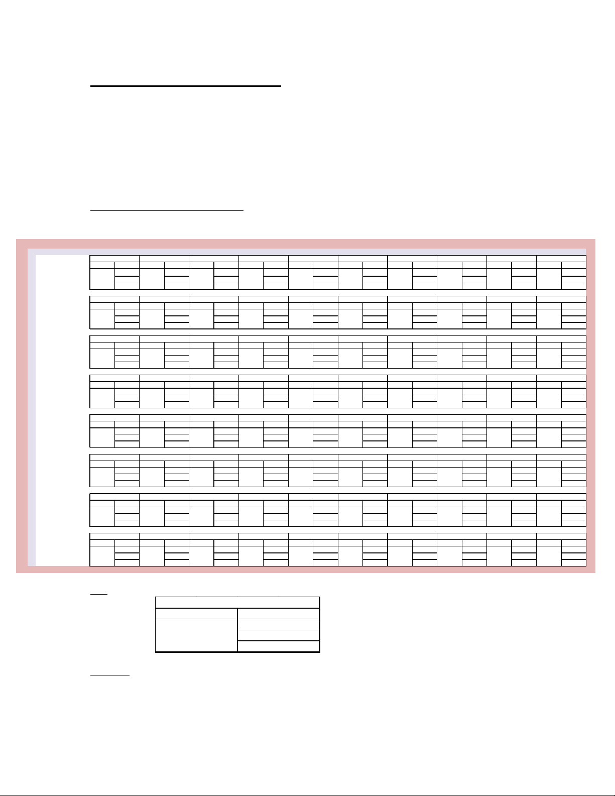
Counter batten length
number required / total x6 7 x9 10 x12 14 x15 17 x18 20 x21 27 x24 27 x27 31 x30 34 x33 37
Support Battens (m) 4 7 9 12 15 18 20 23 26 29
In-Fill Battens (m) 2 5 7 9 12 14 17 19 21 24
Total (m) 13 21 30 38 47 59 64 73 81 90
Counter batten length
number required / total x6 13 x9 19 x12 26 x15 32 x18 38 x21 45 x24 51 x27 57 x30 64 x33 70
Support Battens (m) 4 7 9 12 15 18 20 23 26 29
In-Fill Battens (m) 2 5 7 9 12 14 17 19 21 24
Total (m) 19 30 42 53 65 76 88 99 111 122
Counter batten length
number required / total x6 19 x9 28 x12 37 x15 47 x18 56 x21 65 x24 75 x27 84 x30 93 x33 103
Support Battens (m) 4 7 9 12 15 18 20 23 26 29
In-Fill Battens (m) 2 5 7 9 12 14 17 19 21 24
Total (m) 25 39 54 68 83 97 112 126 141 155
Counter batten length
number required / total x6 25 x9 37 x12 49 x15 62 x18 74 x21 86 x24 99 x27 111 x30 123 x33 135
Support Battens (m) 4 7 9 12 15 18 20 23 26 29
In-Fill Battens (m) 2 5 7 9 12 14 17 19 21 24
Total (m) 31 48 66 83 100 118 135 153 170 188
Counter batten length
number required / total x6 31 x9 46 x12 61 x15 76 x18 92 x21 107 x24 122 x27 138 x30 153 x33 168
Support Battens (m) 4 7 9 12 15 18 20 23 26 29
In-Fill Battens (m) 2 5 7 9 12 14 17 19 21 24
Total (m) 37 57 77 98 118 139 159 180 200 220
Counter batten length
number required / total x6 37 x9 55 x12 74 x15 92 x18 110 x21 128 x24 147 x27 165 x30 183 x33 201
Support Battens (m) 4 7 9 12 15 15 15 23 26 29
In-Fill Battens (m) 2 5 7 9 12 12 12 19 21 24
Total (m) 43 66 90 113 137 155 174 207 230 253
Counter batten length
number required / total x6 43 x9 64 x12 85 x15 107 x18 128 x21 149 x24 170 x27 192 x30 213 x33 234
Support Battens (m) 4 7 9 12 15 15 15 23 26 29
In-Fill Battens (m) 2 5 7 9 12 12 12 19 21 24
Total (m) 49 75 101 128 155 176 197 234 260 286
Counter batten length
number required / total x6 49 x9 73 x12 97 x15 121 x18 146 x21 170 x24 194 x27 218 x30 242 x33 267
Support Battens (m) 4 7 9 12 15 15 15 23 26 29
In-Fill Battens (m) 2 5 7 9 12 12 12 19 21 24
Total (m) 55 84 113 142 173 197 221 260 289 319
4321
5095mm5095mm5095mm
5
98765
8
7075
7
6085mm6085mm
6
5095mm 5095mm 5095mm
4105mm
5095mm 5095mm 5095mm 5095mm
4105mm 4105mm4105mm 4105mm 4105mm 4105mm
4
4105mm 4105mm
7075
8065 8065
4105mm
3115mm 3115mm 3115mm 3115mm 3115mm 3115mm
2125mm 2125mm 2125mm 2125mm
3
3115mm 3115mm 3115mm 3115mm
1135mm 1135mm
2
2125mm 2125mm 2125mm 2125mm 2125mm 2125mm
10
1
1135mm 1135mm 1135mm 1135mm 1135mm 1135mm 1135mm 1135mm
Number of panels - Horizontal
6085mm 6085mm 6085mm 6085mm6085mm 6085mm 6085mm 6085mm
7075 7075 70757075 7075 7075 7075
Number of panels -Vertical
8065 8065 8065 80658065 8065 8065 8065
7075
in-fill batten total
Total (m)
Length of counter batten (mm)
number required counter batten total
support batten total
Positioning the Solar Panel Array
For best visual effect, it may be necessary to position the panel array with equal
distance from eave to ridge, and centrally from verge to verge. Use the counter
batten table overleaf to calculate the vertical height of the array. Use the sum of
fitted solar panel widths plus one overall panel width for the total width of the
array. E.g. for a three panel wide system the sum is 1377mm + 1377mm +
1394mm = 4148mm.
Counter batten requirements
Key
Example
If you have 3 vertical panels and 3 horizontal panels, you will need 12 x 3115mm counter battens,
(37.38m of batten in total).
The vertical height of the array is 3115mm
The total width of the array is 4148mm.

7
Visual Guide to the use of the Sandtoft PV48 template

8
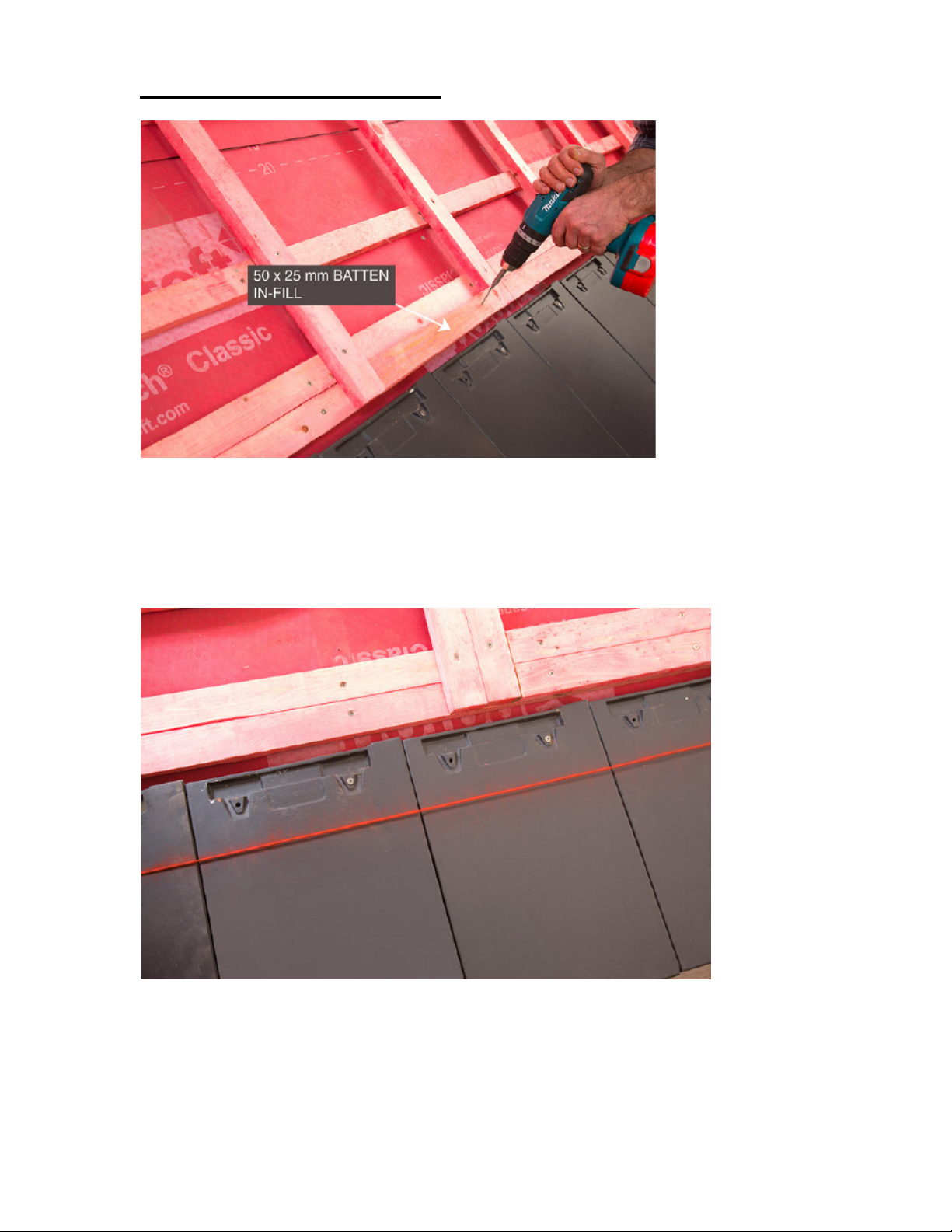
Preparing the roof
Firstly prepare the area where the solar panels are to be fitted. This may involve
stripping off the existing roof covering, if this is the case, the existing tiles may
need to be lowered to ground level, stacking some aside for re-use as required.
In order to counteract wind uplift the existing battens in the area where the panels
are to be fitted must be screwed to the rafters. Use the 70mm screws provided.
If installing a new roof, batten out the roof as usual, and screw to the rafters as
previously stated.
Additional battens need to be fitted to support the solar panel’s front apron
flashing and counter battens are needed to support the solar panels.
The first additional batten is fitted 100 -150mm above the tile batten (depending
on tile profile). A second batten is fixed directly above it. Use a chalk line to
ensure the batten is perfectly parallel with the tile batten.
Fix these battens to the rafters with 70mm screws.
9
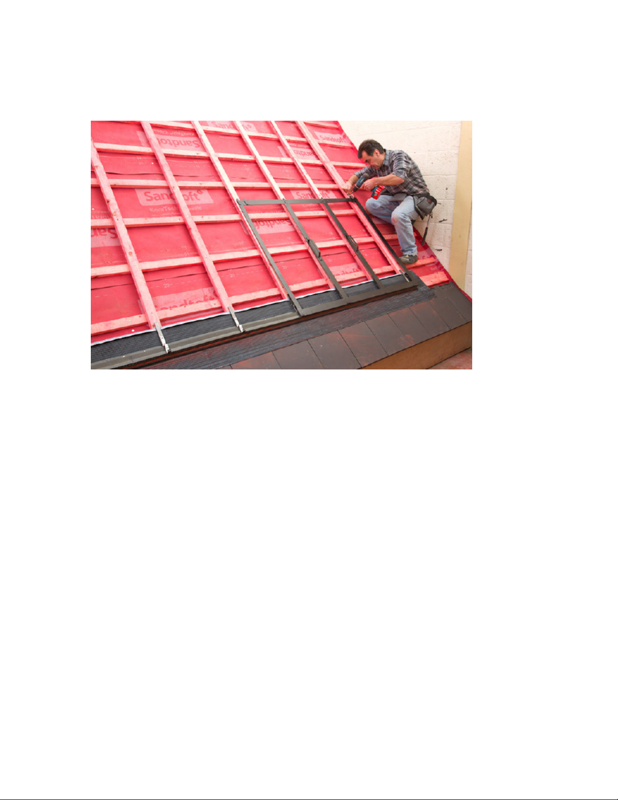
Marking out the Counter battens
Position the template at the bottom right hand corner of the designated solar
panel area. Lay the template onto the battens to enable you to mark where the
counter battens will be fitted. See photo below.
Installation tip: screw the template to the top batten to help keep the template in
position and perfectly square while you mark the edge of the template.
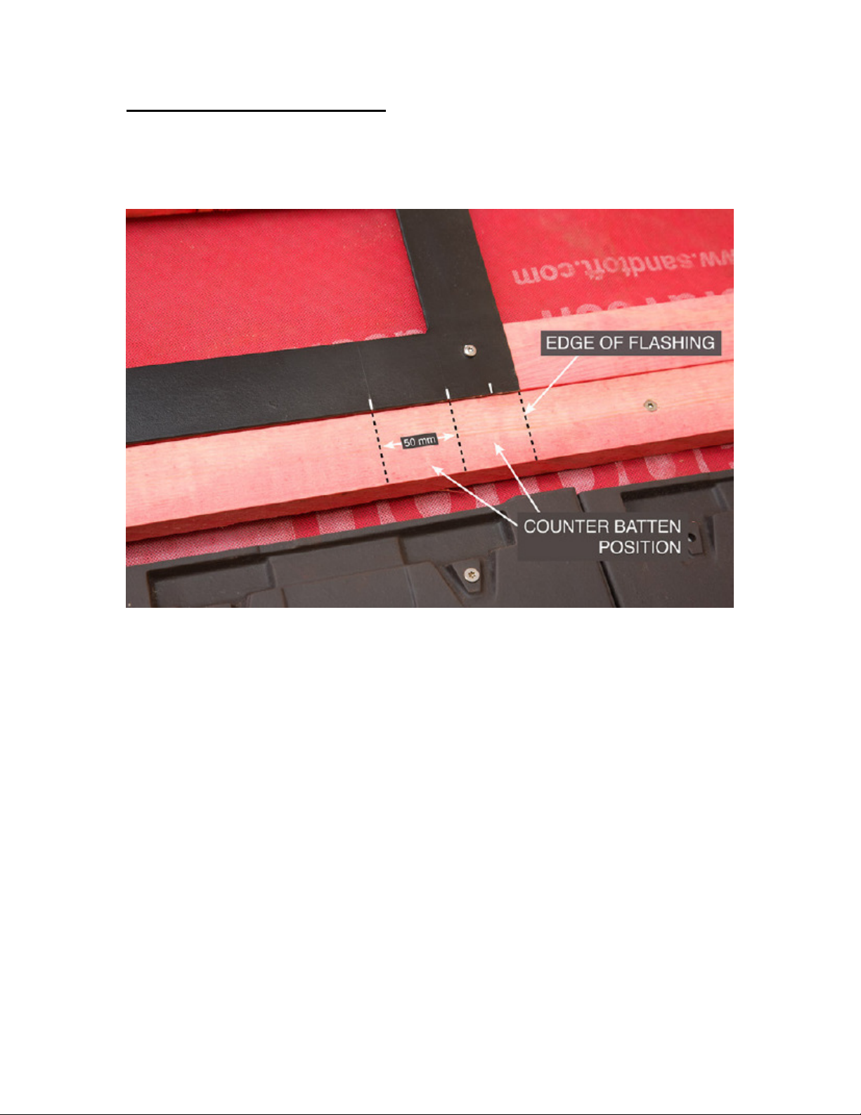
Mark the batten at the bottom of the template where the edge of the template
ends. This represents the junction between the flashing and the panel.
Make a second mark on the batten at the bottom of the template 50mm (counter
batten position) in and make a third at 50mm (counter batten position)
10
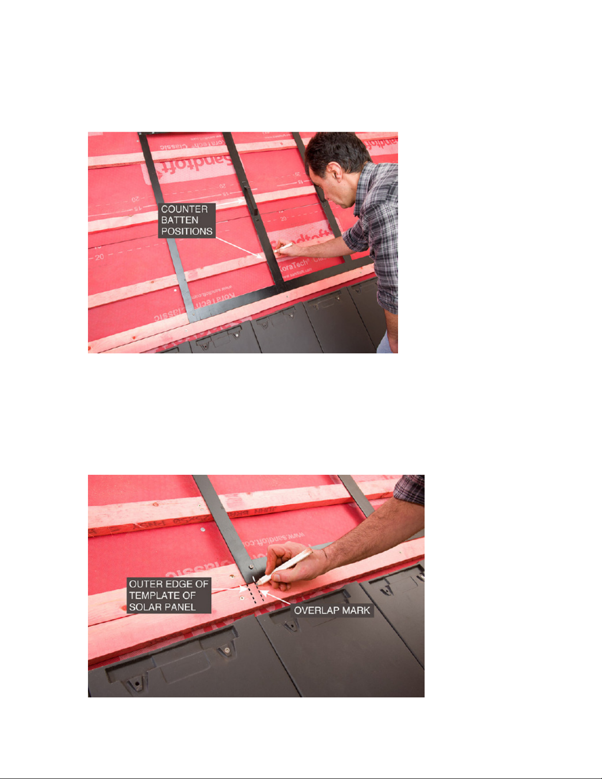
Mark the counter batten positions onto all the battens where the template's cross
bars lay across them. Mark both left and right hand edges of the template’s cross
bars.
At the left hand corner of the template mark the outside edge of the template
which indicates the outer edge of the solar panel.
Make a second mark which indicates the overlap of the adjacent solar panel.
11
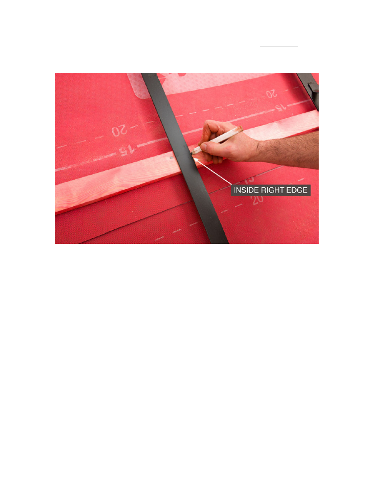
Now moving up the template - make a mark only where the inside edge of the
template cross bar rests on the batten. This indicates the inside right edge of the
counter batten.
THE ACCURACY OF THIS MARK IS CRUCIAL TO THE INTEGRITY OF THE
INSTALLATION - AS IT ENSURES THAT THE FIXING BRACKET IS
POSITIONED CENTRALLY ON THE COUNTER BATTEN.

12
Move the template across to the left.
Position the bottom right hand edge of the template with the overlap mark you
have made on the batten (not the outer edge mark). Screw the template to the
battens for continued accuracy. Do not mark for counter battens at this corner.
Mark on all the battens where the template cross bars lay across them, both at
the left and right hand edges of the template’s cross bars. This indicates where
the counter battens are to be positioned.
Only ever mark the outer edge of the template if this coincides with the outer
edge of the designated panel area. Otherwise mark the inside counter batten
line as previously stated.

13
Note: These instructions are based on a 2 x 2 panel configuration, and so
this point is the bottom left hand corner of the solar panel array. IF YOUR
ARRAY IS WIDER THAN 2 PANELS PLEASE REPEAT AS PER PREVIOUS
PAGE FOR EACH ADDITIONAL PANEL.
At the bottom left hand corner of the designated panel area:
At the bottom left hand corner, mark the outside left hand edge of the template
Mark the batten (50mm) from the outer edge and make another mark (50mm).
These marks represent the counter batten positions for the left hand side of the
designated panel area.
Also mark the left hand outer edge of the template where the template's cross
bars lay across the battens.

14
Fitting the counter battens
Position the bottom of the counter batten to line up with the bottom of the front
apron support batten. Fix the counter batten to the battens with 45mm screws, for
the height of the template only. Do not continue up the roof at this stage.
Fit a second counter batten adjacent to, and on the inside of, the first counter
batten. This will carry the fixing bracket fixings for the solar panel. This
configuration of two battens is required only at the outside edges of the
designated panel area. Screw the second counter batten to the battens for the
height of the template only.
Continue to fit counter battens to the roof to match the markings made on the
battens.
Screw all counter battens to the battens in the area of the template only. This
allows for the re-alignment of the unsecured length of the counter battens at a
later stage.
Note: The counter battens need securing approximately every 300 - 400mm with
the 45mm screws provided
At the left hand edge of the designated panel area fit a final counter batten to the
outer marks.
Fit an additional counter batten to the inside of the final batten. This
configuration of two battens is required only at the outside edges of the
designated panel area. Screw the second counter batten to the battens for the
height of the template only. This additional counter batten will carry the fixing
bracket fixings for the outer left hand edge of the array of panels.
15
Preparing the front apron flashing
The gaps between the counter battens can now be in-filled. Use 50 x 25mm
battens cut to size and screw them into the battens. Use two fillers per gap. This
creates a support for the apron flashing which is to be created using Koraflex.
Note: Koraflex is an aluminium roll, fully coated with a butyl adhesive backing.
Strike a chalk line to mark the bottom of the apron flashing. Allow for a minimum
of 100mm cover over the head of the tile/slate. This leaves 220mm of Koraflex
to be dressed up over the front apron support battens.

16
Cut a piece of Koraflex 150mm wide and fit it at the bottom outside corner (not
pictured). Repeat the process at the bottom left hand corner. This will create a
double layer of Koraflex at the front corners for added protection..
Measure a length of Koraflex for the front apron so that it has a minimum side-lap
of 175mm at both the left and right hand sides.
This measurement allows for a 25mm upstand at the side of the counter batten
whilst maintaining a 150mm sidelap.
Secure the Koraflex onto each counter batten 40mm down from the top edge,
using 20mm galvanized clout nails. Dress the Koraflex firmly onto the tiles.
Tip: Use the square edge of a lead dresser to ensure that the upstand is clearly
visible.

17
After dressing the Koraflex, carefully remove the lower backing strip from the
Koraflex and dress into final position on the tiles.
Installing the Sandtoft ventilation strip
Measure down from an existing batten, mark both left and right and strike a line
between.
Position the Sandtoft ventilation strip over the Koraflex, ensuring correct
orientation. Fix with 20mm galvanized clout nails or 20mm screws through the
upper flat edge of the strip. See photo below. You may need to cut the final piece
of Ventilation strip to size.
Tip. Avoid fixing the screws where there is a counter batten as this may coincide
with a panel fixing bracket which will be fitted later

18
Use the template to check that the ventilation strip is at right angles to the
counterbattens.
Create a ‘welt’ by turning the top and side edges of the Koraflex flashing over,
this will stop any wind driven rain from entering the batten cavity.
Place the template in line with the extreme right side counter batten.
In the bottom left hand corner of the template, mark the outer edge and overlap
marks onto the ventilation strip. This indicates the position of the fixing bracket
which will later be located centrally between them.
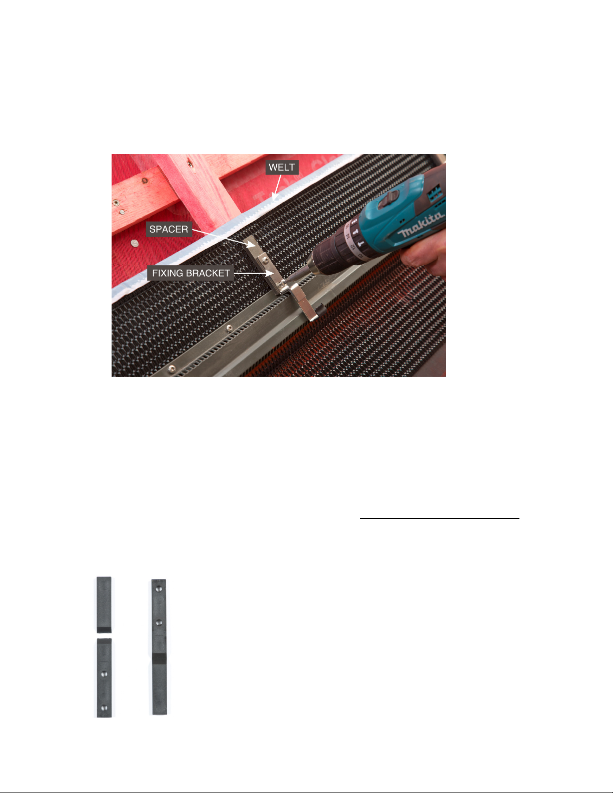
19
Fit the fixing brackets with the spacers* in the configuration shown, centrally to
the counter battens, on top of the ventilation strip. Use the 30mm screws
supplied. Continue to fit the fixing brackets and spacers along the length of the
ventilation strip.
The butyl backing of the Koraflex will self-seal the screw holes.
* The fixing bracket spacer is supplied at size 140 mm however it is designed to
be used in two different lengths during the installation. The spacer is scored to
allow it to be broken into a shorter length piece of 80mm for use where specified
in this guide. See photo below.
The shorter length 80 mm spacers are to be used only at the bottom of the array
i.e. at the ventilation strip. Full length 140 mm spacers are used everywhere else
on the array.
Tip: Be careful to break the correct quantity of spacers
into short lengths 80mm. i.e. only those that will be required at
the ventilation strip at the bottom front edge of the array of
panels.
20
The photo below shows the fixing brackets and plastic spacers fixed to the
counter battens above the ventilation strip. The template is resting on the fixing
brackets in preparation for the fixing of the next row of fixing brackets.
Table of contents
Popular Inverter manuals by other brands

Scheppach
Scheppach SG1200 Translation from the original instruction manual

Giandel
Giandel PS-3000QBR user manual

Sunlight Supply
Sunlight Supply Titan Controls Selene 1 instruction manual

Kohler
Kohler 99EOZDJ installation instructions

Siemens
Siemens SINAMICS G120P manual

Cyber Power
Cyber Power CPS1000EILCD user manual

ring
ring PowerSourcePure Series instruction manual

Mitsubishi Electric
Mitsubishi Electric F700 instruction manual

Tripp Lite
Tripp Lite PV1000FC Features & specifications

Winco
Winco WL22000VE/A Installation and operator's manual

INHENERGY
INHENERGY HI-3K-SL user manual

Mastervolt
Mastervolt WHISPER 9.5 ULTRA installation manual


