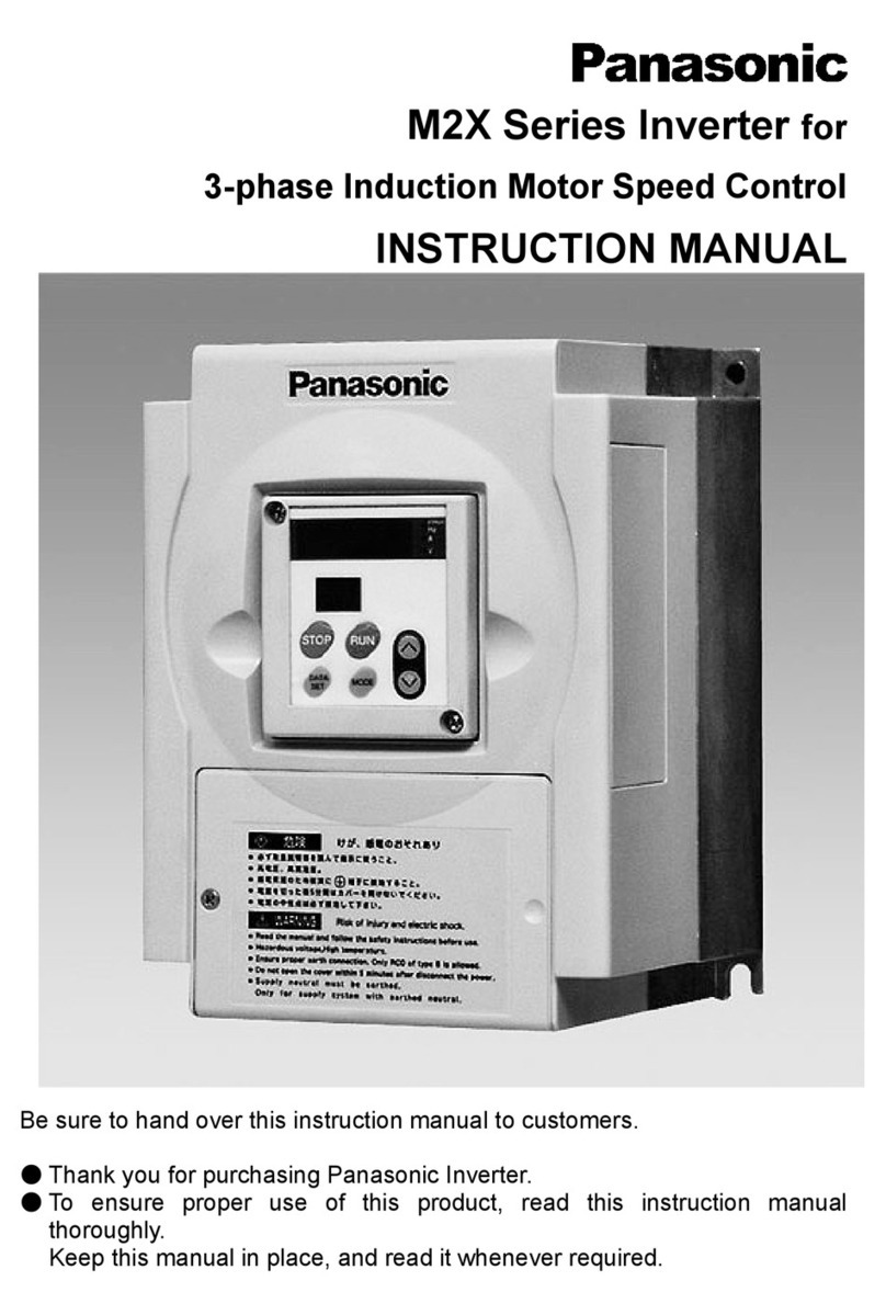
Panasonic VF200 User manual

VF200
WME-VF200-A
2013.01 panasonic.net/id/pidsx/global


Foreword
Thank you for purchasing Panasonic products.
- For optimum performance and safety, please read this manual carefully before
using this product.
- Please save this manual for future use.
Applicability of the Product
•This general-purpose inverter manufactured by us is not designed or
manufactured to be used in machine or system in situationsthat can affect or
endanger human life.
Before using this product in special applications such as machinery or
systems in movable object, medical, aerospace, nuclear energy control,
submarine relay equipments or systems, please contact us.
•Although this product was manufactured under strict quality control system, it
is strongly recommended to install safety devices to prevent serious accidents
when used in facilities where a breakdown of this product is likely to cause a
seriousinjury or major losses.
•Do not use this product for loads otherthan a 3-phase induction motor.

i
Table of contents
Safety Precautions .........................................................................1
Points for Handling ........................................................................ 9
Special Precautions ...........................................................................10
1. Parts Identification ...................................................................13
1.1 Part Names and Functions ........................................................14
1.2 Details on Part Number...............................................................16
2. Installation ...............................................................................17
2.1 Safety Precautions .................................................................... 18
2.2 Installation Precautions .............................................................. 19
2.3 Outline Dimensions .................................................................... 21
2.4 Removal and Installation of Operation Panel ............................ 23
3. Wiring .......................................................................................25
3.1 Safety Precautions .................................................................... 26
3.2 Removal and Installation of Terminal Cover ............................ 27
3.3 Wiring (Main Circuit) ................................................................. 29
3.4 Wiring (Control Circuit) ............................................................. 33
4. Operation Method(Basic Operation) .......................................43
4.1 Safety Precautions .................................................................... 44
4.2 Description of Operation Panel/Simple Panel ........................... 45
4.3 Operation Modes ....................................................................... 47
4.4 Type of Operation Method ......................................................... 50

ii
Table of contents
4.5 Setting Frequency with Operation Panel ................................ 51
4.6 Setting Forward/Reverse Run with Operation Panel ............... 52
4.7 Operating with Operation Panel ............................................... 54
5. Control Status Monitor..............................................................69
5.1 List of Control Status Monitor Items ...........................................70
5.2 Introduction of Monitor No ..........................................................72
6. Function Parameters ...............................................................81
6.1 Setting and Changing Function Parameters .............................. 82
6.2 Function Parameter List ............................................................. 86
7. Custom Mode ...........................................................................95
7.1 Allocating Parameter No............................................................. 96
7.2 Setting and Changing Parameters .............................................98
8. Setting Modes and Copy Functions of Built-in Memory ........101
8.1 Setting Modes and Copy Functions of Built-in Memory ........... 102
8.2 Setting Built-in Memory Parameters ....................................... 103
8.3 Parameter Upload Function (CPY1) ........................................ 105
9. Troubleshooting......................................................................113
9.1 Safety Precautions ............... ........................................ .......... 114
9.2 Abnormality Diagnostic Function and Resetting Method ......... 114
9.3 Handling Abnormalities .................... ....................................... 118
8.4 Parameter Download Function (CPY2) ................................... 107
8.5 Parameter Verification Function .............................................. 109
8.6 To Display or Conceal Built-in Memory Setting Mode ............. 111
iii
Table of contents
10. Maintenance and Inspection ................................................121
10.1 Safety Precautions .................................................................122
10.2 Precautions on Inspection ......................................................122
10.4 Component Replacement ...................................................... 124
10.3 Inspection Items .................................................................... 122
10.5 Maintenance and Inspection Table ........................................ 125
11. Specifications .......................................................................129
11.1 Rated Specifications .............................................................. 130
11.2 Standard Specifications ..........................................................132
11.3 Common Specifications ..........................................................133
Appendix .....................................................................................139
Function Parameter List ..................................................................140
Precautions on European Standard Directives ..........................277
Conditions of CE Marking ..........................................................278
Warranty.....................................................................................279
“Administrative Measures for Control of Pollution
Caused by Electronic Information Products” in
China Names and Content Marks of Toxic or
Hazardous Substances and Elements .......................................276


1
Safety Precautions

Safety Precautions
2
Safety Precautions
Read this manual and related documents before attempting to install,
operate, service or inspect the inverter.
Make sure that you have a full understanding of the device, the safety
information and all precautions before starting use.
Precautions described in this manual are divided into two grades:
“Danger” and “Caution”.
: Indicates dangerous situations that could lead to
injury or death in case of mishandling.
: Indicates dangerous situations that could lead to
moderate or minor injury or property damage in
case of mishandling.
In addition, failure to follow the precautions in
may also lead to serious situations depending on conditions.
Since the precautions of the above two grades are of critical importance,
please make sure to obverse them strictly.

Safety Precautions
3
1. Installation
Caution
• Install the unit on non-flammable material, such as metal, etc. Failure to
do so may lead to fire.
• Do not place the unit near flammable materials. Failure to do so may lead
to fire.
• Do not hold the unit by terminal cover while transporting it. Failure to do
so may cause the unit to drop and result in injury.
• Do not let foreign matter such as metal sheet enter into the unit. Failure
to do so may lead to fire.
• Install the unit on a place strong enough to support the weight of
it according to the instruction manual. Failure to do so may lead to
dropping of the unit and thus result in injury.
• Do not install or operate an inverter that is damaged or with part(s)
missing. Failure to do so may result in injury.
2. Wiring
Danger
• Always make sure that power is OFF before starting wiring. Failure to do
so may result in an electric shock or fire.
• Always connect ground wire. Failure to do so may result in an electric
shock or fire.
• Wiring work should always be carried out by qualified electrician. Failure
to do so may result in an electric shock or fire.
• Always install the unit before wiring. Failure to do so may result in an
electric shock or injury.

Safety Precautions
4
Caution
• Do not connect an AC power supply to output terminals (U, V, W). Failure
to do so may result in injury or fire.
• Make sure that the voltage rating of the product matches with that of
AC power supply. Or it may result in injury and fire.
• Tighten terminal screws to specified torque. Failure to do so may lead to
fire.
3. Operation
Danger
• Always close terminal cover before turning ON inlet power . Do not open
the terminal cover while the power is ON. Failure to do so may result
in an electric shock or fire.
• Do not operate the switches or dials with wet hands. Failure to do so may
result in an electric shock.
• Do not touch inverter terminals even when the inverter is stopped while
power ON. Failure to do so may result in an electric shock.
• The STOP button is not designed for emergency stop purposes. Set a
separate button for emergency stop. Failure to do so may result in injury.
• Depending on the start mode and settings of ride-through function, if
operating signal is ON or the power is restored from a power failure, the
inverter may start (or restart) suddenly. Keep away from the unit to avoid
injury.
Design the machine so that it can ensure personal safety even if the
inverter starts suddenly.
• Depending on the setting of start mode function, when reset fault trip
with the operating signal present, the inverter may restart suddenly.
〔
〕

Safety Precautions
5
(Always take measures to ensure personal safety.) Failure to do so may
result in injury.
• When retry function is in use, the unit may automatically start (restart)
suddenly, so do not approach the unit. (Always take measures to ensure
personal safety.) Failure to do so may result in injury.
• While auto-tuning function is in use, the inverter will automatically drive
the motor in the stand-along mode when the RUN button on the panel is
pressed.
(Always take measures to ensure personal safety.) Failure to do so may
result in injury.
• If data change during operation, variations of the motor and motor load
may change drastically and sudden stop will occur.
(Always take measures to ensure personal safety.) Failure to do so may
result in injury.
Caution
• The heat sink and braking resistors are under high temperature, so do
not touch them. Doing so may result in burns.
• The inverter can be easily set to operate from low speed to high speed.
Confirm the allowable range of motor and machine carefully during setup.
Failure to do so may result in injury.
• Set separate holding brakes if required. Failure to do so may result in
injury.

Safety Precautions
6
4. Maintenance, Inspection and Part Replacement
Danger
• Wait at least five minutes after turning OFF inlet power before starting
maintenance and inspection. Failure to do so may result in an electric
shock.
• Maintenance, inspection and part replacement work must be done only
by qualified persons.
[Remove all metal personal belongings (watches, bracelets, etc.) before
starting work.] (Use tools treated with insulation.) Failure to do so may
result in an electric shock or injury.
Caution
• Employ an electrical engineering company to periodically tighten the
terminal screws. Loosen screws may lead to overheating or fire.
5. Others
Danger
• Never modify the unit. Failure to do so may result in injury.
6. General Precautions
All diagrams in this instruction manual show the state with the cover or safety
partitions removed to explain the details. Be sure to replace the covers and
partitions in position, and then operate the unit according to the instruction
manual.

Safety Precautions
7
7. Warning Label on Inverter
VF200

Safety Precautions
8

9
Points for Handling
Special Precautions............................................................ 10

Points for Handling
10
Special Precautions
Use the inverter only within allowable ambient temperature range
(-10~50°C).
Since service life of the inverter is greatly affected by ambient temperature, use
it within allowable temperature range. Also, observe the installation directions
and conditions. (Refer to P.21)
The inverter will be damaged if the power voltage is applied to its
output side.
Applying power voltage tothe output terminal U, V or W will damage the
inverter. Check carefully for faulty wiring and operation sequence (commercial
switching circuit, etc.). Never apply a voltage exceeding the allowable range.
Never touch inside of the inverter during operation.
Failure to do so could be extremely dangerous, since the inverter contains
high-voltage circuit. Before making an internal check, be sure to wait at least 5
minutes after turning OFF the inverter. Do nottouch heat sink or braking
resistor during operation as these parts are under high temperature.
Radio interference
The main circuit of the inverter contains a high-frequency harmonic component
and may interfere with communicating equipments (such as AM radio) nearby.
The severity of interference depends on the radio field strength and is hard to
be eliminated completely. Whileit may be reduced by relocating radio antenna,
using noise filter, housing the inverter in a metal box, or routing cables in
conduit. (Please inquire separately.)
Do not conductinsulation test between wires of the inverter.
To measure insulation resistance between power cord and motor wires, please
remove the cables connected to the inverter and conduct test with them. Do not
conduct insulation test on the control circuits. However, insulation test can be
performed between charging unit and the ground.

Points for Handling
11
Do not use a magnetic contactor which is connected to power side or
load side of the inverter to start or stop the motor (inverter).
Frequent ON/OFF switching on the power supply side can cause inverter
malfunction. Also, do not conduct ON/OFF switching on load side during
inverter operation, or it can cause fault trip of the inverter. Start or stop the
motor by operating signals of the inverter only.
Do not connect a power capacitor or a surge absorber to output side
of the inverter.
Such device can damage the inverter, resulting in broken of capacitors and
other parts. Remove it if connected.
Do not use the inverter for load other than a motor or for a 1-phase
motor.
If parameters are frequently written in, service life of built-in
non-volatile memory (EEPROM) of the inverter will be shortened.
The maximum life of non-volatile memory (EEPROM) used in VF200 is
100,000 times. Therefore, do not write in parameters frequently.
Precautions for inverter's protection function
The inverter integrates various protection functions such as stall prevention,
current limiting and over-current shut-off. These protection functions are
functions used to protect the inverter against the sudden abnormal conditions,
instead of general control functions.
Therefore, avoid using themin applications where they will be activated under
normal conditions.
Failure to do so may reduce the inverter's service life or damage the inverter.
Always measure the output current, etc. with a meter, check the details of the
fault trip memory, and confirm that operation conditions conform tothe
precautions and specifications are correct.

Points for Handling

13
1
Parts Identification
1.1 Part Names and Functions..............................14
1.2 Details on Part Number ...................................16
Table of contents
Other Panasonic Inverter manuals

Panasonic
Panasonic S-200PE2E5 Manual

Panasonic
Panasonic EVERVOLT EVHB-I7 User manual

Panasonic
Panasonic M2X Series User manual

Panasonic
Panasonic U-200PE1E8 Manual

Panasonic
Panasonic S-200PE2E5 Manual

Panasonic
Panasonic S-160PE1R5A Manual

Panasonic
Panasonic U-26PE1U6 Manual

Panasonic
Panasonic AMK3000P22 User manual

Panasonic
Panasonic VF0 Series 400V class User manual

Panasonic
Panasonic M1S Series User manual