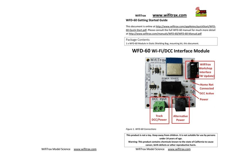
WifiTrax Model Science WFD-46 User manual

WFD-46 Wi-Fi/DCC Booster Module Operating Manual
P a g e | 1 WifiTrax Model Science
www.wifitrax.com
WFD-46 Wi-Fi/DCC Booster Module with
Output Voltage Adjustment
Operating Manual
This document is online at http://www.wifitrax.com/manuals/WFD-46/WFD-46-Manual.pdf.
Please see our website for information on our limited warranty.
WifiTrax Model Science
www.wifitrax.com
Version 1.0 November 30, 2020
© WifiTrax Model Science 2020 All Rights Reserved

WFD-46 Wi-Fi/DCC Booster Module Operating Manual
P a g e | 2 WifiTrax Model Science
www.wifitrax.com
This product is not a toy. Keep away from children. It is not suitable for use by persons under 14 years of age.
Warning: This product contains chemicals known to the state of California to cause cancer, birth defects or
other reproductive harm.

WFD-46 Wi-Fi/DCC Booster Module Operating Manual
P a g e | 3 WifiTrax Model Science
www.wifitrax.com
Version History
Version
Changes
1.0
First Release, Version 1 Firmware

WFD-46 Wi-Fi/DCC Booster Module Operating Manual
P a g e | 4 WifiTrax Model Science
www.wifitrax.com
Table of Contents
Version History........................................................................................................................................3
Table of Contents....................................................................................................................................4
Table of Figures.......................................................................................................................................6
Scope of this Document..........................................................................................................................7
What does WFD-46 Wi-Fi/DCC Booster Do? ..........................................................................................8
Let’s get Started!...................................................................................................................................13
Installing your new WFD-46 on Your Layout ....................................................................................13
Usage Scenarios of WFD-46..............................................................................................................13
Getting Started with a WFD-28 Wi-Fi Command Station .................................................................14
Getting Started with a WFD-27 Wi-Fi Command Station/Booster ...................................................15
Using the WFD-46 Web Pages ..............................................................................................................17
Accessing the WFD-46 Setup Web Pages using a Web Browser ......................................................17
Setup Advanced Features using a Web Browser...............................................................................17
General Settings Web Page...............................................................................................................17
IP Address......................................................................................................................................18
Region Code..................................................................................................................................18
Serial Number ...............................................................................................................................18
Firmware Version..........................................................................................................................18
Module Name ...............................................................................................................................19
Wi-Fi Channel................................................................................................................................19
Net Number ..................................................................................................................................19
Over Current Timeout mS.............................................................................................................19
Current Calibration .......................................................................................................................20
LEDs Disabled................................................................................................................................20
Home Net Web Page.........................................................................................................................20
FindModules App..........................................................................................................................21
Changing IP Addresses due to Router Restart ..............................................................................23
DCC Status.........................................................................................................................................23
Power Valid...................................................................................................................................23
Factory Reset ....................................................................................................................................24
Factory Reset Button ........................................................................................................................24
Adjusting the Output DCC Voltage of the WFD-46...............................................................................25
Power Districts and Making Use of the Auto-Reverse Feature ............................................................27
Tips to Manage your Home Network....................................................................................................29

WFD-46 Wi-Fi/DCC Booster Module Operating Manual
P a g e | 5 WifiTrax Model Science
www.wifitrax.com
A few Things to Know........................................................................................................................29
Connection to your Home Router.....................................................................................................29
Why does my module fail to connect to the router? .......................................................................29
Home Net IP Address Assignment ....................................................................................................30
Finding the IP Address Assigned to your WFD-46 Module...............................................................30
Reserving a Fixed IP Address.............................................................................................................33
More Information..................................................................................................................................34
FCC Information....................................................................................................................................35
EU Declaration of Conformity................................................................................................................35

WFD-46 Wi-Fi/DCC Booster Module Operating Manual
P a g e | 6 WifiTrax Model Science
www.wifitrax.com
Table of Figures
Figure 1 WFD-46 in Context. A WFD-27 Command Station/Booster is used to Supply a DCC Signal to
the WFD-46 and also Supplies DCC to the First Power District ..............................................................8
Figure 2 WFD-46 in Context. A WFD-28 Command Station is used to Supply a DCC Signal to two WFD-
46 via a DCC Control Bus Cable. Each WFD-46 Supplies a Separate Power District...............................9
Figure 3 Connections, switches, LEDs etc. on the WFD-46...................................................................11
Figure 4 Mounting the WFD-46 on a Baseboard ..................................................................................13
Figure 5 Connecting a WFD-46 to a WFD-28 Wi-Fi Command Station.................................................14
Figure 6 Connecting a WFD-46 to a WFD-27 Wi-Fi Command Station/Booster...................................15
Figure 7 The WFD-46 Web Setup Main Menu......................................................................................17
Figure 8 The WFD-46 General Settings Web Page................................................................................18
Figure 9 The WFD-46 Home Net Web Page..........................................................................................21
Figure 10 The FindModules Screen.......................................................................................................22
Figure 11 The FindModules tool shows that the correct subnet has been found................................22
Figure 12 The FindModules tool shows that the WFD-46 Module and others have been found........23
Figure 13 The WFD-46 DCC Status Page ...............................................................................................23
Figure 14 Factory reset confirmation page...........................................................................................24
Figure 15 Peak-to Peak Voltage of a DCC Voltage Waveform. .............................................................25
Figure 16 Voltmeter Connections to Measure the Track DCC Voltage.................................................26
Figure 17 Typical Arrangement using three WFD-46 with Return Loop...............................................27
Figure 18 Using ipconfig to find your computer's IP Address and Default Gateway............................31
Figure 19 Access your router by using the IP Address of your default gateway in a browser .............31
Figure 20 A typical router admin page..................................................................................................32
Figure 21 Typical "Attached Devices" page of a router ........................................................................32
Figure 22 Use the IP Address to open the main menu web page.........................................................33
Figure 23 An IP Address reservation table in a router..........................................................................33
Figure 24 Adding an address reservation .............................................................................................34
Figure 25 Identifying Illustration for WifiTrax Model WFD-46 EU Declaration of Conformity.............36

WFD-46 Wi-Fi/DCC Booster Module Operating Manual
P a g e | 7 WifiTrax Model Science
www.wifitrax.com
Scope of this Document
This document describes detailed use of the WFD-46 Wi-Fi/DCC Booster Module. For a simple
starting guide, please see the leaflet at http://www.wifitrax.com/appNotes/quickStart/WFD-46-
Quick-Start.pdf.
This manual applies to firmware version 1, i.e., version numbers 1.X.X.

WFD-46 Wi-Fi/DCC Booster Module Operating Manual
P a g e | 8 WifiTrax Model Science
www.wifitrax.com
What does WFD-46 Wi-Fi/DCC Booster Do?
Network Router
Wi-Fi Range
Gap in
Both
Tracks
Power District 1 Power District 2
WFD-46
Command Station
e.g. WFD-27
Figure 1 WFD-46 in Context. A WFD-27 Command Station/Booster is used to Supply a DCC Signal to the WFD-46 and also
Supplies DCC to the First Power District

WFD-46 Wi-Fi/DCC Booster Module Operating Manual
P a g e | 9 WifiTrax Model Science
www.wifitrax.com
Network Router
Wi-Fi Range
Gap in
Both
Tracks
Power District 1 Power District 2
WFD-46
WFD-28
Command Station
WFD-46
DCC Control Bus
DCC Control
Bus
Figure 2 WFD-46 in Context. A WFD-28 Command Station is used to Supply a DCC Signal to two WFD-46 via a DCC Control
Bus Cable. Each WFD-46 Supplies a Separate Power District
The WFD-46 Wi-Fi/DCC Booster is a 5 Amp/3 Amp DCC Booster that receives a DCC signal from a DCC
Command Station and delivers high-power DCC Power to a Power District consisting of a section of
track isolated by a gap in both rails. Here is a summary of its features:
•5 Amp continuous capability
•Variable DCC Output Voltage 9.8 Volts –20 Volts in two ranges
•3 Amp or 5 Amp Overcurrent Protection
•Input from Track DCC or DCC Control Bus
•Auto-reversing for return loops, wye etc.
•Wi-Fi Monitoring of Status
•DCC Control Bus Loop-through for Effectively Unlimited Chaining

WFD-46 Wi-Fi/DCC Booster Module Operating Manual
P a g e | 10 WifiTrax Model Science
www.wifitrax.com
Switch
Function
On
Off
Remarks
1
Output Voltage Range
Range 1
9.8V to 15V PP
Range 2
13V to 20V PP
Range 1 needs 18V Input
Range 2 needs 24V Input
2
Overcurrent Shutdown
3 Amp
6 Amp
3
DCC Input Source
Control Bus
RJ-11 Socket
Track DCC
Terminals
4
Auto Reverse Enable
Disabled
Enabled
Table 1 WFD-46 DIP Switch Settings
The output bipolar DCC to the track, rated at 5 Amp continuous can be adjusted in two ranges:
Range 1: 9.8 Volts to 15 Volts Peak-Peak with an 18 Volt DC input
Range 2: 13 Volts to 20 Volts Peak-Peak with a 20 Volt DC input
The range is selected using a dip switch number 1 on the module as Table 1.
Short circuit protection is provided and may be set at 3 Amp or 5 Amp by dipswitch 2 on the module
as Table 1. The booster will cut off power when the current drawn goes significantly above that
level.
The booster may receive its input DCC signal either from track bipolar DCC or a DCC Control Bus. This
is specified by Dip Switch 3 in Table 1.
Figure 1 shows it receiving its input signal from a WFD-27 Wi-Fi/DCC Command Station Booster. In
this configuration, the WFD-27 provides DCC track power to one power district and the WFD-46
supplies DCC track power to another. Both are protected independently against short circuits on the
track.
Figure 2 shows a WFD-28 Wi-Fi/DCC Command Station Only providing input DCC signal via a control
bus to two WFD-46 which each provide DCC track power to a separate power district.
When Auto-reverse is enabled by Dip Switch 1 in Table 1, the DCC output to the track will reverse
very quickly as soon as a locomotive causes a short by bridging one or both of the gaps between two
blocks or power districts with opposite polarity. Once one of the blocks has switched the short will
no longer exist and the loco will proceed. Note that if two adjacent districts are powered by WFD-46,
only one will normally reverse but it will be indeterminate. To be sure which one reverses, you can
disable auto reversing on one of the WFD-46.
You can access the Web Pages of each WFD-46 to adjust certain settings or view their status. Consult
the section “Using the WFD-46 Web Pages” for details.

WFD-46 Wi-Fi/DCC Booster Module Operating Manual
P a g e | 11 WifiTrax Model Science
www.wifitrax.com
Bipolar DCC
Track
Output
Bipolar
Track DCC
Input
Alternative
Power
18V-24V
Power
18V-24V
Control Bus
Input/Output
Control Bus
Input/Output
Red Power LED
Green Net LED
Blue DCC Normal LED
Yellow DCC Reversed LED
Factory Reset
(Press and hold until green LED flashes)
Firmware
Update
DIP Switches ON
OFF
1234
DCC Voltage Adjust
Clockwise to Increase
Figure 3 Connections, switches, LEDs etc. on the WFD-46
Figure 3 shows the WFD-46 module with its connectors labelled.
There is a pair of screw connectors at left that provide bipolar track DCC output to power the section
of track controlled by the booster.
DCC Input may be provided using one or other of the Control Bus Input/Outputs, the other then
being available to loop on to another WFD-46 module.
Alternatively, DCC input may be provided using the two screw terminals near the bottom right,
marked Bipolar Track DCC Input. To select one or the other use DIP Switch 3 as Table 1. When DCC
Input is taken from the Bipolar Track DCC Input, both of the Control Bus Sockets act as outputs than
can be connected to the Control Bus inputs of another WFD-46 module.
Power between 18V and 24V DC can be provided using the Power Barrel Connector Socket, in which
case the Alternative Power Screw Terminals are available as Power Output to another module.
Otherwise, the Alternative Power terminals can be used as input power to the module. The correct
polarity must be observed, but the module is protected against accidental reversal.
The 6-Pin connector at the top right is used for firmware update via a Wifitrax FWA-20 module and
the Wifitrax Workshop software for Windows.
The Factory Reset button will reset the module to its factory default settings when pressed and held
for 8-10 seconds. The green LED will flash rapidly when reset has been started. All settings will revert
to factory default and any home net settings will be lost.
The DIP Switches in the middle are described in Table 1.
Turn the Voltage Adjust screw clockwise to increase the output voltage and counter-clockwise to
decrease it.

WFD-46 Wi-Fi/DCC Booster Module Operating Manual
P a g e | 12 WifiTrax Model Science
www.wifitrax.com
The LEDs at the top are:
(1) Red LED - Power: Lights whenever power is applied to the module.
(2) Green LED –Network: Flashes when the module receives Wi-Fi Network Traffic. Lights
continuously when the module is connected to a home network router and flashes briefly
off when module receives traffic.
(3) Yellow LED –DCC: Lights continuously when a valid DCC input is present at the module and
the output is reversed.
(4) Blue LED –DCC: Lights continuously when a valid DCC input is present at the module and the
output is not reversed. Flashed rapidly when a short has been detected and the track output
is shut down. Flashes slowly when the voltage of the power input is not adequate to provide
the required output voltage

WFD-46 Wi-Fi/DCC Booster Module Operating Manual
P a g e | 13 WifiTrax Model Science
www.wifitrax.com
Let’s get Started!
Installing your new WFD-46 on Your Layout
Board
Components On WFD-46
WFD-46 PCB M3 Screw
Plastic Spacer
M3 Nut M3 Washer
Figure 4 Mounting the WFD-46 on a Baseboard
Mount the WFD-46 module on a convenient board on your layout using the mounting kit provided.
You may also mount it inside a suitable plastic box. Do not use a metal box as this will affect the Wi-
Fi signal.
It is most important that the module never comes into contact with any metal objects or any
power such as your track! The electronics uses 3.3 Volts provided by an on-board voltage stabilizer
and contact with any higher voltages will destroy it.
All the WFD-46 capability can be used without using its Wi-Fi features, but connecting to its Wi-Fi
access point provides useful information about its performance on your layout. These Wi-Fi features
are described in Section “Using the WFD-46 Web Pages”on page 17.
Usage Scenarios of WFD-46
The WFD-46 provides a single output of Bipolar DCC to the track exactly like any other DCC Booster.
It does not contain a DCC Command Station so you cannot use it alone to control trains; instead, you
must supply an input DCC signal from a DCC Command Station and that command station generates
the commands to locomotives and accessories. That signal can be provided as Bipolar Track DCC or
as a DCC Control Bus.
The WFD-46 also provides a DCC Control Bus output that can be used as the input to other WFD-46
modules.
It is the way these inputs and outputs are connected that scenarios the context of the WFD-46, that
is, the way it fits into the DCC system controlling your layout.
In this Getting Started section, we will consider two common contexts:
(1) One DCC Power District using one WFD-46 with a WFD-28 Wi-Fi Command Station,
(2) Two DCC Power Districts using one WFD-46 with a WFD-27 Wi-Fi Command Station/Booster.
If you already have a WFD-27 and are adding a Booster, use scenario (2).

WFD-46 Wi-Fi/DCC Booster Module Operating Manual
P a g e | 14 WifiTrax Model Science
www.wifitrax.com
Getting Started with a WFD-28 Wi-Fi Command Station
Power District 1
WFD-28
Command Station
WFD-46 DCC Control
Bus 18 or 24
Volt DC
Power
Adapter
Bipolar
Track
Dcc
Power Adapter Cable
Power
Looped
through to
WFD-46
Figure 5 Connecting a WFD-46 to a WFD-28 Wi-Fi Command Station
Here we suppose you have bought both a WFD-28 Wi-Fi Command Station and a WFD-46 Wi-Fi
Booster, You’ve already mounted them on your layout and want to connect them up and get
started. Figure 5 shows how to connect these up and the steps are below:
(1) Connect a Power Adapter to the WFD-28 Command Station. Both the WFD-28 and the WFD-
46 (the Command Station and the Booster) need power. The power adapter that you select
depends on the voltage and current requirements of your layout. 14 Volts is usually
considered a suitable peak to peak voltage for DCC used on HO locomotives. The WFD-46
has a voltage adjustment which is set to 14 Volts on leaving the factory. An 18 Volt power
adapter is recommended with at least 5 Amp capacity.
(2) Connect power “looped-through”from the Command Station to the Booster. Use the
Alternative Power screw terminals as a power Output to supply the WFD-46 Booster. Make
sure that you observe the correct polarity. The WFD-46 Booster is protected against power
reversal but it is best not to rely on it. The module will not work in a power-reversed
situation.
(3) Use a Command Bus cable to connect the DCC Command Bus output from the WFD-44
Command Station to one of the Command Bus inputs on the WFD-46 Booster. The
Command Bus cable uses an RJ9 or RJ10 (4P4C) connector at each end. The cables should be
“Straight-through”, that is not reversed. You can buy DCC Control Bus cables from various
DCC manufactures such as NCE, you can make your own, or you can order one from Wifitrax.
(4) Connect the Track Output from the WFD-46 Booster to your track. It does not matter which
way around but it is a good idea to adopt a convention and stick to it when you add more
boosters. That way, all the power districts will be in-phase unless you reverse on using Auto-
Reverse or manually using the Wi-Fi Web Pages.
(5) Check the DIP Switch settings on your WFD-46 Booster (See Table 1 for details). It is
recommended that the initial settings for simple, single district operation is as Table 2.
(6) Check all your connections, place a locomotive on the track with a known DCC address and
turn on power.

WFD-46 Wi-Fi/DCC Booster Module Operating Manual
P a g e | 15 WifiTrax Model Science
www.wifitrax.com
(7) Consult the Quick Start Guide for WFD-28 or the WFD-28 Manual to beginning running
trains.
Switch
Function
Recommended
Setting
Remarks
1
Output Voltage Range
On
Range 1: 14 Volts Output
2
Overcurrent
Shutdown
On
3 Amp Shutdown
3
DCC Input Source
On
Control Bus Input
4
Auto Reverse Enable
On
Auto Reverse Disabled
Table 2 WFD-46 DIP Switch Settings for Simple Single Power District Operation
Getting Started with a WFD-27 Wi-Fi Command Station/Booster
Power District 2
WFD-27 Command
Station/Booster
WFD-46 18 or 24
Volt DC
Power
Adapter
Bipolar
Track
Dcc
Power Adapter Cable
Power
Looped
through to
WFD-46
Power District 1
Bipolar
Track
Dcc
Gap in
Both
Tracks
Figure 6 Connecting a WFD-46 to a WFD-27 Wi-Fi Command Station/Booster
Here we suppose you already have a WFD-27 Wi-Fi Command Station/Booster and are adding a
WFD-46 Wi-Fi Booster, You’ve already mounted them on your layout and want to connect them up
and get started. Figure 5 shows how to connect these up and the steps are below:
(1) Connect a Power Adapter to the WFD-27 Command Station/Booster. Both the WFD-27 and
the WFD-46 (the Command Station and the Booster) need power. The power adapter that
you select depends on the voltage and current requirements of your layout. 14 Volts is
usually considered a suitable peak to peak voltage for DCC used on HO locomotives. The
WFD-46 has a voltage adjustment which is set to 14 Volts on leaving the factory. An 18 Volt
power adapter is recommended with at least 5 Amp capacity. The WFD-27 does not have
adjustable voltage. Usually the WFD-27 output voltage is about 1 volt below its supply
voltage.
(2) Connect power “looped-through”from the Command Station/Booster to the Booster. Use
the Alternative Power screw terminals as a power Output from the WFD-27 to supply the
WFD-46 Booster. Make sure that you observe the correct polarity. The WFD-46 Booster is
protected against power reversal but it is best not to rely on it. The module will not work in a
power-reversed situation.
(3) Connect the Track Output from the WFD-27 Command Station/Booster to your track. It does
not matter which way around.

WFD-46 Wi-Fi/DCC Booster Module Operating Manual
P a g e | 16 WifiTrax Model Science
www.wifitrax.com
(4) Also connect the Track Output from the WFD-27 to the Track DCC Input screw terminals on
the WFD-46.
(5) Connect the Track Output from the WFD-46 Booster to your track. It does not matter which
way around but it is a good idea to adopt a convention and stick to it when you add more
boosters. That way, all the power districts will be in-phase unless you reverse on using Auto-
Reverse or manually using the Wi-Fi Web Pages.
(6) Check the DIP Switch settings on your WFD-46 Booster (See Table 1 for details). It is
recommended that the initial settings for simple, single district operation is as Table 3. Note
that the DCC Input Source is set to Track DCC Terminals and the Auto-Reverse is enabled.
This will allow the WFD-46 to set its output polarity correctly when a locomotive bridges the
gaps at the junction between power districts.
(7) Check all your connections, place a locomotive on the track with a known DCC address and
turn on power.
(8) Consult the Quick Start Guide for WFD-27 or the WFD-27 Manual to beginning running
trains.
Switch
Function
Recommended
Setting
Remarks
1
Output Voltage Range
On
Range 1: 14 Volts Output
2
Overcurrent
Shutdown
On
3 Amp Shutdown
3
DCC Input Source
Off
Track DCC Terminals
4
Auto Reverse Enable
Off
Auto Reverse Enabled
Table 3 WFD-46 DIP Switch Settings for Dual District Operation with a WFD-27 Command Station/Booster

WFD-46 Wi-Fi/DCC Booster Module Operating Manual
P a g e | 17 WifiTrax Model Science
www.wifitrax.com
Using the WFD-46 Web Pages
The WFD-46 provides many features which are made available via web pages that you can access
with a browser.
Accessing the WFD-46 Setup Web Pages using a Web Browser
Setup Advanced Features using a Web Browser
On your hand-held device or computer open a browser such as in Table 4.
Device
Operating System
Browser Options
iPhone, iPad
IOS
Safari
Android Tablet or Phone
Android
Chrome
Windows Computer
Windows XP, 7, 8, 10,11
Internet Explorer, Edge,
Chrome, etc.
Table 4 Web Browsers available on different platforms
(1) If you are working in Direct Mode, connect your device to the Wi-Fi Access Point of your
WFD-46, that is wftrx_WFD46_1_XXXXXXXX_7, where XXXXXXXX is the 8-digit serial number.
If you are working in Home Net mode connect your device to your home net.
(2) Type the IP Address of the WFD-46 into the Address Bar of the browser.
a. In Direct Mode type 192.168.7.1 and hit the enter key or “Go” button (the http://
may appear automatically. Do NOT use “https” (the WFD-46 does not support
secure sockets).
b. In Home Net mode, type the IP Address that was assigned by your router and hit the
enter key. Please see the section “Tips to Manage your Home Network”on page 29
to see how to find this out.
Figure 7 The WFD-46 Web Setup Main Menu
(3) You should now see the Web Setup Main Menu as in Figure 7. You can click or tap on any of
the headings in the menu to access the setup for that feature.
General Settings Web Page
To modify General Settings, tap the “Settings” heading in Figure 7.

WFD-46 Wi-Fi/DCC Booster Module Operating Manual
P a g e | 18 WifiTrax Model Science
www.wifitrax.com
Figure 8 The WFD-46 General Settings Web Page
The first line contains the IP address (IP), the Region Code (Rg) and the Serial Number (SN)
IP Address
If you are working in direct mode this will display 192.168.7.1. If you are in Home-Net mode it will
display the IP Address assigned to the module by your router. You cannot change this from the
Settings page, but you should keep a note of it since it is needed to access these Web Pages. Better
still add it to your browser favourites and consider setting an IP Address Reservation in your router..
Region Code
This will be 0 for all regions other than the Americas or 1 for North and South America. In the
Americas only Wi-Fi channels 1 –11 are allowed whereas in the rest of the world 1 –13 are
permitted, both by law and by the firmware.
Serial Number
This is a unique number for your particular module. You may be asked for this if you request help or
report a problem to Wifitrax.
The second line shows Firmware Version (F/W Ver.), Heap space Maximum/Current/Minimum over
a period of a minute and a reset count.
Firmware Version
This is the version of the WFD-46 firmware installed at the factory. You cannot change this but if you
ask for WifiTrax support, you may be asked for it. You can upgrade your firmware using WifiTrax
Workshop and the FWA-20 Workshop Adapter Module.

WFD-46 Wi-Fi/DCC Booster Module Operating Manual
P a g e | 19 WifiTrax Model Science
www.wifitrax.com
Module Name
This defaults to the value SNXXXXXXXX where XXXXXXXX is the 8-digit serial number. You can change
this to a name up to 10 characters long which cannot include spaces. Type the name you want in the
text box (such as “Booster1”) and tap Save.
Wi-Fi Channel
This is the Wi-Fi channel in the 2.4GHz Wi-Fi band that the WFD-46 will use only when operating in
Direct Mode. It will have no effect in Home Net mode as the channel will be determined by your
router. You can set the channel to a value from 1 to 13, (1 to 11 in the Americas) and the default
value is 1 after a factory reset. You do not normally need to change this but it may be helpful if other
interfering devices are being used nearby. You need to cycle power before the channel change will
have an effect. Once you have cycled power, the WFD-46 Wi-Fi access point will be of the form
wftrx_WFD46_N_XXXXXXXX_7 where N is your selected channel.
Note: Only channels 1 to 11 may be used in North and South America and Taiwan, 1 to 13 may be
used in Europe and Asia/Pacific. It is your responsibility to avoid breaking the law by adhering to
these conditions.
Net Number
This defines the subnet that the WFD-46 will use to set its own IP Address and to allocate IP
Addresses to hand-held devices that connect in Direct Mode.
It has no effect in Home Net mode.
If you change this value, by typing an integer from 1 to 14 and tapping Save, the WFD-46 will use this
after cycling power. The subnet will be 192.168.N.0 where N is the net number. The unit’s IP Address
will then be 192.168.N.1 and it will assign IP Addresses: 192.168.N.2 to 192.168.N.5
The WFD-46 Wi-Fi access point will be of the form wftrx_WFD46_1_XXXXXXXX_N where N is your
selected net number.
Over Current Timeout mS
This is the time in milli-Seconds that an overcurrent situation is tolerated before the booster shuts
down its output. This should normally be set as short as possible to avoid any damage to wiring,
track or locomotives in the event of a direct short. When the DIP Switch 2 is set to the On position,
the shutdown threshold will be somewhat greater than 3 Amps. When the DIP Switch 2 is set to the
Off position, the shutdown threshold will be around 6 Amps. Once this threshold is reached, the
module will shut down its output after the Overcurrent Timeout has elapsed. When shutdown
occurs, the blue DCC LED will blink rapidly. After a short period of time, output will be restored and if
the short persists, the module will shut down again.
Sometimes users install an auto-reverser or overcurrent protection device in addition to that
provided by the WFD-46. In this case the WFD-46 Overcurrent Timeout can be made longer to avoid
premature shutdown before the other device has time to operate.

WFD-46 Wi-Fi/DCC Booster Module Operating Manual
P a g e | 20 WifiTrax Model Science
www.wifitrax.com
Current Calibration
This is an advanced feature and requires electronic tools for its use, that is an ammeter and a high-
power resister or other device to provide a load of at least an amp. Do not click these buttons
unless these tools are available or you will lose the factory calibration and be unable to restore the
current readout.
You cannot use the built-in web browser in the WiThrottle or Engine Driver apps to do this. You
must use a full browser such as Edge, Chrome or Safari. This is because the built-in app browsers
do not allow the warning pop-ups to be displayed.
The WFD-46 has on-board measurement of the approximate current being drawn by the equipment
(locos, accessories, etc.) on the power district it supplies. This is calibrated before leaving the factory
but the calibration can be repeated by the user.
The calibration consists of an offset and slope value. The displayed current is calculated according to
the following equation:
Where is the measured load current that is displayed,
is the Analog to Digital Converter
reading on the module, is the calibrated offset value and is the calibrated slope value.
To recalibrate the Offset, remove all loads from the WFD-46 module and click the “Calibrate Offset”
button. A popup warning appears. Make sure the conditions are correct, then click OK.
To recalibrate the Slope, connect a load resistor with a series ammeter in place of the track
connections, type the value of the current indicated on the ammeter, in mA, in the Measured
Current textbox. The value must be between 1000mA and 6999mA, that is, between 1 and 6.999
Amp. When this is correct click the “Calibrate Slope”button. A popup will warn you. If everything is
correct, click OK to continue.
LEDs Disabled
When this checkbox is checked, the LEDs on the module are disabled, except the red Power LED.
Some users may be annoyed by flashing LEDs and use this to reduce distraction.
Home Net Web Page
Remember, Direct Mode is when you connect your tablet or computer to the module’s access point,
wftrx_WFD46_1_XXXXXXXX_7. Home-Net mode is when the module connects itself to your router
and you access it via your router.
This page allows you to change your WFD-46 from Direct Mode to Home Net Mode and back again.
Once you have changed to Home-Net mode, you will not be able to work in Direct Mode, but if for
some reason the WFD-46 cannot join your Home Net (maybe you typed it wrong, put in the wrong
password or the router was turned off), the WFD-46 will attempt to connect for about 30 seconds
then revert to Direct mode. You will then see the wftrx_WFD46_1_XXXXXXXX_7 access point which
you can connect to and correct the problem. It’s always worth restarting your home router if you’ve
checked everything and connection does not succeed, as these so often seem to get locked up
somehow!
Other manuals for WFD-46
1
Table of contents
Other WifiTrax Model Science Control Unit manuals
Popular Control Unit manuals by other brands
L&S
L&S SMART 4 quick start guide
Alpha Technologies
Alpha Technologies Cordex 030-728 Installation & operation manual
McConnel
McConnel 5 Service XTC Mk2 PROPORTIONAL SWITCHBOX... quick start guide

EUCHNER
EUCHNER MBM-PN MLI Series operating instructions
Frequency Central
Frequency Central System X Filter Build documentation

CLA-VAL
CLA-VAL 90-01 Installation operation & maintenance

