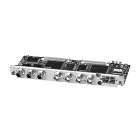
Sony DSBK-100 User manual

1997 by Sony Corporation
3-859-819-02(1)
J
EN
F
D
I
取扱説明書 2ページ
Operating Instructions Page 11
Mode d’emploi Page 19
Bedienungsanleitung Seite 27
Istruzioni per l’uso pagina 35
お買い上げいただきありがとうございます。
電気製品は、安全のための注意事項を守らない
と、火災や人身事故になることがあります。
•ご使用にあたっては、デジタルビデオカセットプレーヤー
本体に付属の取扱説明書の「安全のために」と「 警告」、
「注意」をよくお読みください。お読みになったあとは、
いつでも見られるところに必ず保管してください。
•本基板の取り付けは、必ずお買い上げ店またはソニーの
サービス窓口にご依頼ください。
DSBK-100/100P
警告
SDI Output Board

2
警告表示の意味
取扱説明書および製品では、次のような表示をしていま
す。表示の内容をよく理解してから本文をお読みくださ
い。
警告
この表示の注意事項を守らないと、火災や感電などによ
り死亡や大けがなど人身事故につながることがあります。
日本語

3
目次
概要 .................................................................................................... 4
DSBK-100の構成品 .................................................................................. 4
警告................................................................................................ 5
取り付け ............................................................................................. 5
準備 ............................................................................................................5
取り付け手順 ..............................................................................................6
取り扱い説明
設置説明
日
本
語
J

4
SDIアウトプットボードDSBK-100は、ソニーデジタルビデオカセットプレーヤーDSR-60のた
めのオプション基板です。本基板をDSR-60に取り付けることにより、SDI(シリアルデジタル
インターフェース)フォーマットのデジタルビデオ/オーディオ信号の出力が可能になります。
本基板を取り付けたあとの接続や出力信号の仕様については、DSR-60の取扱説明書をご
覧ください。
DSBK-100の構成品
DSBK-100は、下記の品目で構成されています。
概要
ケーブル (2組)(
コネクターの色が黒・赤のものが1組)
ネジ (×2)
SDI-28基板
コネクターパネル
ノイズフィルター

5
準備
取り付け作業を始める前に、SDI-28基板にケーブルを接続しておいてください。
•コネクターが黒色のケーブルを、基板上のBLACKと表示されているコネクターに接続
します。
•コネクターが赤色のケーブルを、基板上のREDと表示されているコネクターに接続し
ます。
お客様へ
以下の設置説明 (「取り付け」の項)は、特約店およびソニーのサービス窓口用の設置説
明書です。
お客様がこの設置説明書に記載された作業を行うと、火災や、感電やけがなどの人身事
故につながることがあります。
お客様自身では絶対に取り付け作業をしないでください。
本基板の取り付けは、必ずお買い上げ店またはソニーのサービス窓口にご依頼ください。
警告
ケーブル
黒色のコネクターa)
赤色のコネクターa)
BLACKの表示がある
コネクター REDの表示があるコネクター
SDI-28基板
a) ノイズフィルター(前ページの図参照)から遠い方のコネクター
取り付け

6
レバーを起こしてから、
基板を抜き取る。
←DVの刻印
DV-17基板
①
A
Aの方向から見て、コネクター間
にすき間ができないように完全に
結合させる。
DV-17基板
SDI-28基板
取り付け
天板
ネジ
ネジ
ネジ
DSR-60
基板押さえ (2)
基板押さえ (1)
SDI-28基板
金属カバーに開いている穴の中を
見て、周囲に白い斜線が見えるネ
ジ穴を選ぶ。
DV-17基板の金属カバー
すき間がある。
すき間がない。
取り付け手順
1DSR-60の天板を取り外し、次に基板
押さえ (1) および (2) を取り外す。
2DV-17基板を取り外す。
DV-17基板は、DSR-60の前面から見
て左から2番目のスロットに 装 着され
ています。スロットフレームの 刻 印←
DVで確認してください。
ご注意
取り外した基板は、金属カバーを下側
にして、机やテーブルの上面など平
坦な面に静かに置いてください。
3SDI-28基板のコネクターを、DV-17基
板のコネクターにしっかりと差し込む。
4DSBK-100に付属のネジ2本で、SDI-
28基板とDV-17基板を互いに固定す
る。

7
(続く)
ブランクパネル
SDI-28基板
DV-17基板
配線止め
5「準備」(5ページ) でSDI-28基板に
接続した 2 本のケーブルを、図のよ
うなルートでDV-17基板上にはわせ、
配線止め (2本) を巻きつけて固定
する。
6DV-17基板を、DSR-60の基板スロット
に戻す。
両端のレバーを倒し、両手で確実に
奥まで差し込んでください。
7SDI-28基板に接続したケーブルを基
板スロットの後面パネル側にある溝に
入れる。
8DSR-60の後面パネルのブランクパネ
ルの2 か所のネジとワッシャーを外し、
ブランクパネルを右にずらして取り外
す。
ご注意
ブランクパネルは保管してください。

8
取り付け
黒色のコネクター
赤色のコネクター
コネクターパネル
ケーブル収納スペース
クランプ
ノイズフィルター
92本のケーブルの端をブランクパネル
を外したあとの穴から外に出し、コネ
クターパネルに接続する。
ご注意
接続に際しては、ケーブルのコネク
ターの色に注意して、必ず図に示す
並び順で接続してください。
10コネクターパネルをDSR-60の後面パ
ネルに取り付ける。
ケーブルを内側に引きながら、コネク
ターパネルを差し込んで、左にずら
し、手順 8で外した2本のネジとワッ
シャーで、コネクターパネルを固定し
ます。
11コネクターの色がそれぞれ赤色と黒
色の2本のケーブルを、DSR-60の前
面から見て左側にある2つのクランプ
に 止 め、たるん だ 部 分をノイズフィル
ターとともに、左側のケーブル収納ス
ペースに収納する。

9
ネジ
基板押さえ (2)
ネジ
ネジ
基板押さえ (1)
12手順1で取り外した基板押さえ(1)お
よび (2) を取り付け、次にDSR-60の
天板を取り付ける。
基板押さえ (1) には6対のツメがあり
ます。これらのツメが対応の基板の上
縁をはさむように取り付けてください。


11
English
EN
English
Overview ..........................................................................12
Components of the DSBK-100/100P ................................ 12
Installation .......................................................................13
Preparations ....................................................................... 13
Fitting Procedure ............................................................... 14
Table of Contents
For the customers in the USA
This equipment has been tested and found to comply with the
limits for a Class A digital device, pursuant to Part 15 of the FCC
Rules. These limits are designed to provide reasonable protection
against harmful interference when the equipment is operated in a
commercial environment. This equipment generates, uses, and
can radiate radio frequency energy and, if not installed and used
in accordance with the instruction manual, may cause harmful
interference to radio communications. Operation of this
equipment in a residential area is likely to cause harmful
interference in which case the user will be required to correct the
interference at his own expense.
You are cautioned that any changes or modifications not expressly
approved in this manual could void your authority to operate this
equipment.
The shielded interface cable recommended in this manual must be
used with this equipment in order to comply with the limits for a
digital device pursuant to Subpart B of Part 15 of FCC Rules.
This device complies with Part 15 of the FCC Rules. Operation is
subject to the following two conditions: (1) This device may not
cause harmful interference, and (2) this device must accept any
interference received, including interference that may cause
undesired operation.
For the customers in Canada
This Class A digital apparatus complies with Canadian ICES-003.

12
The DSBK-100/100P SDI Output Board is an option for the Sony DSR-60/
60P Digital Videocassette Player. When this option is fitted in a DSR-60/
60P, it becomes possible to output digital video and audio signals in the
SDI (Serial Digital Interface) format.
For the output signal specifications and connections, refer to the Operating
Instructions for the DSR-60/60P.
Caution
If this option is installed incorrectly, personal injury or damage to
peripheral items may occur due to fire, shock, or other accidental
circumstances. To avoid such risks, installation should be performed by
qualified service personnel.
Components of the DSBK-100/100P
The DSBK-100/100P consists of the following items.
Overview
SDI-28 board
Cables (1 pair with black and red connectors)
Connector panel Screws (×2)
Noise filter

13
Before beginning the installation procedure, connect the cables to the SDI-
28 board.
•Connect the cable with the black connectors to the connector labeled
“BLACK” on the board.
•Connect the cable with the red connectors to the connector labeled
“RED” on the board.
Preparations
Installation
a) Use the connector at the farther end of the cable with respect to the noise filter
(see the illustration on the previous page).
SDI-28 board
Cables
Black connectora)
Red connectora)
Connector labeled “BLACK” Connector labeled “RED”

14
1Remove the top cover from the
DSR-60/60P, then remove the
board retainers (1) and (2).
2Remove the DV-17 board.
Seen from the front of the
DSR-60/60P, the DV-17 board
is in the second slot from the
left. Check that it matches the
“NDV” indication engraved
in the top of the slot frame.
Note
After removing the board,
place it carefully on a level
surface such as a workbench,
with the metal cover
underneath.
3Plug the connector of the SDI-
28 board firmly into the
connector on the DV-17 board.
Raise the levers, then pull
out the board.
DV-17 board
(A)
Push the connector
completely in, so that there is
no gap between the two
connectors as seen along the
direction of arrow (A).
Installation
This way
Screw
Screw Screw
Board retainer (1)
DSR-60/60P
Board retainer (2)
Not this
way
Fitting Procedure
Top cover
“NDV” indication
SDI-28 board
DV-17 board

15
4With the two screws supplied
with the DSBK-100/100P,
fasten the SDI-28 board to the
DV-17 board.
5Pass the two cables (connected
to the SDI-28 board in the
“Preparations” stage) over the
DV-17 board along the
illustrated route and wind the
wire clips around the cables.
6Return the DV-17 board to the
slot in the DSR-60/60P.
7Insert the cables connected to
the SDI-28 board into the slit
in the top of the board slot
frame near the rear panel of the
DSR-60/60P.
SDI-28 board
Metal cover
Looking into holes in
the metal cover, select
the screw holes
surrounded by white
hatching.
(Continued)
Push down the levers at both ends, and
with both hands press the board firmly
into position.
Wire clips
DV-17 board
SDI-28 board

16
Installation
Red connector
Connector panel
Black connector
Cover plate
8Remove the two screws and
washers from the cover plate
on the rear panel of the DSR-
60/60P. Slide the cover plate
to the right, then remove it.
Note
Retain the cover plate.
9Feed the two cables out
through the holes exposed
when the cover plate is
removed, and connect them to
the connector panel, one of the
components of the DSBK-100/
100P.
Note
Be careful to match the cable
connector colors, and connect
them in the sequence shown in
the figure.
10Attach the connector panel to
the rear panel of the DSR-60/
60P.
Pulling the cables back through
the holes, slot the connector
panel into position, then slide it
to the left. Fasten the
connector panel with the two
screws and washers removed
in step 8.

17
11Fasten the pair of cables with
red and black connectors in the
left-side pair of clamps as seen
from the front of the DSR-60/
60P, then stow the noise filter
and the slack portions of cables
neatly in the left-side
partitioned space.
12Reattach the board retainers
(1) and (2) removed in step 1,
then the top cover of the DSR-
60/60P.
The board retainer (1) has six
pairs of tongues. Position the
retainer so that each pair of
tongues holds the upper edge
of the corresponding board.
Partitioned space
Clamp
Noise filter
Screw
Screw
Screw
Board retainer (2)
Board retainer (1)


19
Français
Aperçu..............................................................................20
Composants de la DSBK-100/100P .................................. 20
Installation .......................................................................21
Préparatifs.......................................................................... 21
Procédure d’installation..................................................... 22
F
Français
Pour les utilisateurs au Canada
Cet appareil numérique de la classe A est conforme à la norme
NMB-003 du Canada.
Sommaire

20
La carte de sortie SDI DSBK-100/100P est une option destinée au lecteur
de cassettes vidéo numérique DSR-60/60P Sony. Son insertion dans le
DSR-60/60P permet la sortie de signaux vidéo et audio en format SDI
(Serial Digital Interface).
Voir le mode d’emploi du DSR-60/60P pour les spécifications et connexions des
signaux de sortie.
Attention
Si cette option est incorrectement installée, des blessures physiques ou des
dommages aux éléments périphériques pourront survenir à cause du feu,
d’une décharge électrique ou d’autres circonstances accidentelles. Pour
éviter de tels risques, l’installation doit être faite par un personnel de
service qualifié.
Composants de la DSBK-100/100P
La carte DSBK-100/100P comprend les éléments suivants.
Aperçu
Carte SDI-28
Câble (1 paires avec connecteurs noirs et rouges)
Vis (×2)
Panneau à connecteurs
Filtre antibruit
This manual suits for next models
1
Table of contents
Languages:
Other Sony Control Unit manuals

Sony
Sony BVE-700 User manual

Sony
Sony HDCU3500 User manual

Sony
Sony CCU-50P User manual
Sony
Sony CCU-M5A User manual

Sony
Sony FCB-EV7100 User manual

Sony
Sony MSU-750 User manual

Sony
Sony Clie Gear PEGA-MSB1 User manual

Sony
Sony CCP-9000-C User manual

Sony
Sony CCU-700A User manual
Sony
Sony PCS-DSB1 User manual
Popular Control Unit manuals by other brands

PalmSens
PalmSens EmStat3-MUX8 manual

Allen-Bradley
Allen-Bradley POINT I/O 1734-VHSC5 user manual

Simplex
Simplex 4100-6065 installation instructions

AsahiAV
AsahiAV H-V074-E user manual

SonicWALL
SonicWALL 01-SSC-0027 installation guide

Combat HVAC
Combat HVAC NRG Control Installation, operation and service manual