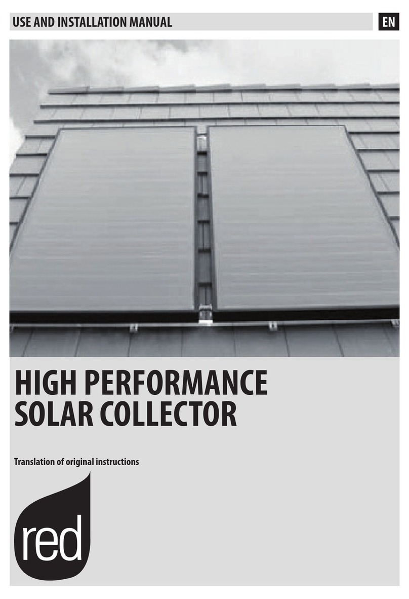
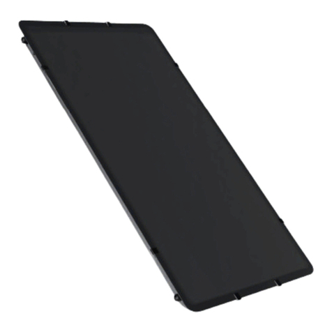
WIKORA Wikosun 2010 User manual

© Wikora GmbH Page 1 Status: 27.04.2015
Errors excepted.
WIKORA GmbH
89568 Hermaringen
Phone: (07322) 9605-0
Fax: (07322) 9605-30
E-mail: contact@wikora.de
Installation manual
On roof mounting/
Flat roof mounting
Flat plate collectors
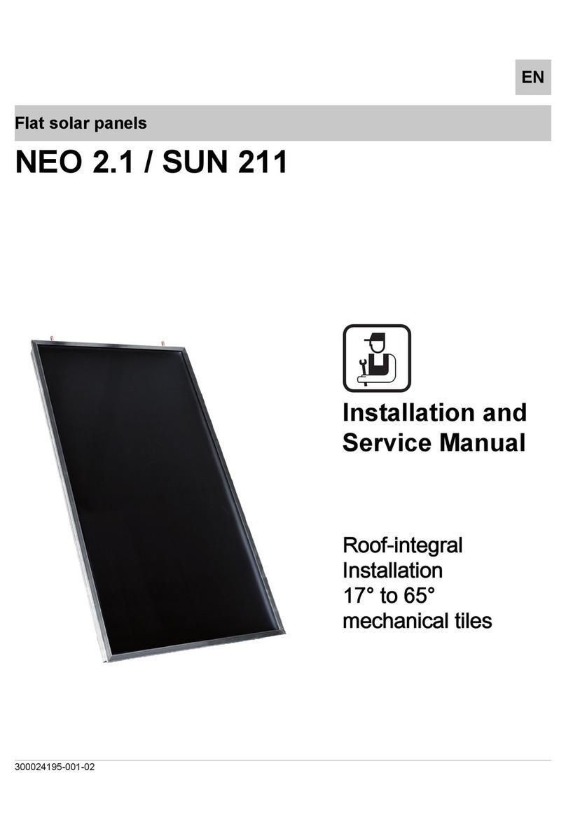
Wikosun 2010 / 2510
Installation and commissioning should be
undertaken by a specialist.
General terms and conditions of warranty state that
all installations must be performed by a suitably
trained and qualified plumber by taking into account
local norms and regulations.
Factory warranty will only be covered if the
installation instructions are followed.
Warranty does not cover any damages, caused by
non-observance of this manual.
The correct functioning is only guaranteed if the
installation instructions are followed.
The system is to be checked annually by a
specialized company. Independently, occurring
defects must be repaired immediately.
This document should be handed over to the
client on completion of works.
Index
1 Transport and storage of collectors ...........................................................................................................................3
2 Mounting accessories ...............................................................................................................................................3
3 Installation..................................................................................................................................................................5
4 Planning and layout data for collectors ....................................................................................................................12
5 Technical data..........................................................................................................................................................13
6 Safety instructions....................................................................................................................................................13
7 General operation and maintenance instruction ......................................................................................................14
8 Solar fluid .................................................................................................................................................................15
9 Warranties ...............................................................................................................................................................17
10 Installation and maintenance record ......................................................................................................................18

© Wikora GmbH Page 2 Status: 27.04.2015
Errors excepted.
Pos. Nr. Description
1
2
3
4
5
6
7
8
9
Collector Wikosun 2010 / 2510
Profile rails, aluminum
Z-clamp
Collector support bracket
Parallel compression fitting 18mm
Compression -X-fitting 18x18x12“x3/4“FD incl. air screw and sensor pocket
Insulation, on site
Compression plug 18mm
Compression-elbow 18mm x 3/4“FD
Chart 1: Part list
5
1
6
9
8
9 2
4
7
5
1
3
8
7
3

© Wikora GmbH Page 3 Status: 27.04.2015
Errors excepted.
1 Transport and storage of collectors
Collectors should be transported in their packaging horizontally (glass facing upward) or vertically. It must be ensured that
collectors can at any time be safely put down (e.g. tilting danger by wind, endangering of other people). Collectors should never
be put down over the edge! Please take special precaution while transporting the collectors on the roof. If collectors can not be
put down at any time and/or if a risk of slipping exists, auxiliary material like safety ropes should be used.
Store collectors in closed and sun-protected areas either horizontally with the glass facing upward or in an upright position. Do
not stack collectors on their connectors.
2 Mounting accessories
2.1 Fastening set “on roof mounting” – vertical / horizontal installation – roof angles from 25-60°
Various fastening sets (tile, adjustable tile, slate, plain tile, corrugated fibre cement, profiled sheeting, stair bolts, standing seam
clamp) are offered for the vertical/horizontal installation of WIKOSUN 2010 / 2510. Each fastening set consists of two mounting
anchors. The total quantity of anchors needed is defined by the number of collectors to be installed and the rafter spacing.
Fastening set
Content
ST-BFS-Z 2 roof hooks tile , 6 wood screws 8x80, 6 washers
ST-BFS-ZV 2 roof hooks adjustable tile, 6 wood screws 8x80, 6 washers
ST-BFS-B 2 roof hooks plain tile, 6 wood screws 8x80, 6 washers
ST-BFS-S 2 roof hooks slate, 6 wood screws 8x80, 6 washers
ST-BFS-BL 2 clamps for rolled steel joist , 2 screws M8, 2 nuts M8
ST-BFS-ST 2 stair bolts M10, 2 ears, 6 nuts, 2 seals
ST-BFS-T 2 roof hooks profiled sheeting
ST-BFS-W 2 roof hooks corrugated sheet iron roofs
Chart 2: Fastening sets „on roof mounting“ – vertical/horizontal installation
2.2 Fastening set “flat roof mounting – vertical installation – roof angles from 30-60°
A basic kit (for 1-2 collectors) and an extension kit (for 1 collector) are offered for the vertical installation of WIKOSUN 2010 /
2510. The basic kit consists of two carriers comprising angle sections with an adjustable tilt angle (30/45/60°), two back bars
comprising flat sections, and a screw set.
The extension kit consists of a carrier comprising angle sections with an adjustable tilt angle (30/45/60°), a back bar comprising
a flat section and a screw set.
Fastening set
Content
Basic kit for 1-2 collectors
WIKOSUN 2010 / 2510
ST-BFS-1FVG
2 Angle sections aluminum 40 x 40 mm, s = 4 mm, l = 1875 mm
2 Angle sections aluminum 40 x 40 mm, s = 4 mm, l = 2140 mm
4 Angle sections aluminum 35 x 55 mm, s = 8 mm; l = 50 mm
2 Flat sections aluminum l = 500 mm, s = 5 mm
2 Flat sections aluminum l = 1920 mm, s = 5 mm
15 Hex head screws, stainless steel M8 x 20 mm
15 Hex nuts, stainless steel M8
15 Lock washers M8
Extension kit for 1 collector
WIKOSUN 2010 / 2510
ST-BFS-1FVE
1 Angle section aluminum 40 x 40 mm, s = 4 mm, l = 1875 mm
1 Angle section aluminum 40 x 40 mm, s = 4 mm, l = 2140 mm
2 Angle sections aluminum 35 x 55 mm, s = 8 mm; l = 50 mm
1 Flat section aluminum 40x5, l = 500 mm
1 Flat section aluminum 40x5, l = 1920 mm
7 Hex head screws, stainless steel M8 x 20 mm
7 Hex nuts, stainless steel M8
7 Lock washers M8
Chart 3: Fastening sets „flat roof mounting“ – horizontal installation

© Wikora GmbH Page 4 Status: 27.04.2015
Errors excepted.
2.3 Fastening set “flat roof mounting – horizontal installation – roof angles from 30-60°
A basic kit (for 1-2 collectors) and an extension kit (for 1 collector) are offered for the horizontal installation of WIKOSUN 2010 /
2510. The basic kit consists of two carriers comprising angle sections with an adjustable tilt angle (30/45/60°), two back bars
comprising flat sections, and a screw set.
The extension kit consists of a carrier comprising angle sections with an adjustable tilt angle (30/45/60°), a back bar comprising
a flat section and a screw set.
Fastening set
Content
Basic kit for 1 collector
WIKOSUN 2010 / 2510
ST-BFS-1FHG
2 Angle sections aluminum 40 x 40 mm, s = 4 mm, l = 1100 mm
2 Angle sections aluminum 40 x 40 mm, s = 4 mm, l = 1250 mm
4 Angle sections aluminum 35 x 55 mm, s = 8 mm; l = 50 mm
2 Flat sections aluminum 40x5 mm, l = 300 mm, s = 5 mm
2 Flat sections aluminum 40x5 mm, l = 1710 mm, s = 5 mm
15 Hex head screws, stainless steel M8 x 20 mm
15 Hex nuts, stainless steel M8
15 Lock washers M8
Extension kit for 1 collector
WIKOSUN 2010 / 2510
ST-BFS-1FHE
1 Angle section aluminum 40 x 40 mm, s = 4 mm, l = 1100 mm
1 Angle section aluminum 40 x 40 mm, s = 4 mm, l = 1250 mm
2 Angle sections aluminum 35 x 55 mm, s = 8 mm; l = 50 mm
1 Flat section aluminum 40x5 mm, l = 300 mm, s = 5 mm
1 Flat section aluminum 40x5 mm, l = 1710 mm, s = 5 mm
7 Hex head screws, stainless steel M8 x 20 mm
7 Hex nuts, stainless steel M8
7 Lock washers M8
Chart 4: Fastening sets „flat roof mounting“ – horizontal installation
2.4 Profile rail sets / Connectors
Profile rail set
Content
ST-PSS-1V 2 profile rails 35x35x 1200mm, 4 Z-clamps, 4 screws M8x20, 4 screws M8x35, 8 nuts M8, 8 washers,
2 K-profiles
ST-PSS-2V 2 profile rails 35x35x 2400mm, 8 Z-clamps, 8 screws M8x20, 6 screws M8x35, 14 nuts M8, 14 washers, 4 K-
profiles
ST-PSS-3V 2 profile rails 35x35x 3600mm, 12 Z-clamps, 12screws M8x20, 8 screws M8x35, 20 nuts M8, 20 washers, 6 K-
profiles
ST-PSS-1H 2 profile rails 35x35x 1800mm, 4 Z-clamps, 4 screws M8x20, 4 screws M8x35, 8 nuts M8, 8 washers,
2 K-profiles
ST-PSS-1.1H 2 profile rails 35x35x 2400mm, 4 Z-clamps, 4 screws M8x20, 4 screws M8x35, 8 nuts M8, 8 washers, 2 K-
profiles
ST-PSS-V 2 Alu angle180mm, 8 screws M8x20, 8 nuts M8, 8 lock washers
Chart 5: Profile rails - horizontal / vertical installation
2.5 Connection accessories
Connection
accessories
Content
ST-AZV-1FK 1 cross piece 18mmxGi1/2“xGi1/2“xGa ¾“, 1 air vent ½“, 1 sensor pocket ½“, 2 end caps 18mm, 2 copper
gaskets ½“, angle 90°18mm x Ga3/4“
ST-VZV-1FK 2 DG-fittings 18mmx18mm
ST-AZH-1FK 1 cross piece 18mm x Gi1/2“ x Gi ½“ x 18mm, 1 air vent ½“ 1 sensor pocket ½“, 2 end caps 18mm, 2 copper
gaskets ½“, 1 angle 90°18mm x 18mm, 2 connecting nipples 18mm x Ga3/4“
ST-VZH-1FK 2 T-piece18mm x 18mm x 18mm, 2 end caps 18mm
Chart 6: Connection accessories - horizontal / vertical installation

© Wikora GmbH Page 5 Status: 27.04.2015
Errors excepted.
3 Installation
3.1 In general
Prior to installation:
•Check the content of the delivery with the delivery note!
•Read the installation instructions carefully and pay attention to the different steps!
•Respect the safety instructions!
This mounting material is structurally approved for assembly with collectors 2010 / 2510 up to a maximum building
height of eight metres. If the collectors are installed on roofs with high wind or snow loads (> 1.0 kN/m²), the load must
be distributed across additional mounts (see chart 2).
3.1.1 Snow/wind load
For structural analysis purposes, we recommend calculations according to DIN 1055. Calculations of the pressure
coefficients (wind) and shape coefficients (snow) are carried out with reference to DIN 1055 -100, DIN 1055-4 and DIN
1055-5. Determine the values of local snow loads according to country-specific data.
Determine the values of local wind loads according to country-specific data. The loads that exist locally (in kN/m²)
must be determined according to the nationally applicable norms. In the case of intermediate values, no interpolation
should be done; instead, the next higher value should be selected.
The values for weighting down the flat roof mounting systems to cope with the wind load can be found on page 8
(chart 8).
Necessary tools Application
Socket key or ratch with extension SW 13
Combination spanner SW 13
Open-ended spanner SW 21
Open-ended spanner SW 27
Pipe tongs
Drill d=9mm
Angle grinder
Hacksaw
Installation of carriers, profile rails and Z-clamps
Sensor pocket
Parallel compression fitting
Variable adjustment of tilt angle
Tile adjustment
Shortening of vertical angle profiles at angle of 30/45°
Chart 7: Tool list

© Wikora GmbH Page 6 Status: 27.04.2015
Errors excepted.
3.2 On roof mounting
3.2.1 Positioining of collectors
Wind loads on roofs can create suction forces on the solar
collectors. In order to minimize suction forces, the distance
between the outer edge of the roof and the collector should be
minimum 70 cm (about 3 tiles). The distance from the roof ridge
should be approx. 2 tile rows (see fig. 1).
. Fig. 1: Positioning of collectors
3.2.2 Fixation of brackets
Measure the area of the collector field on the roof and define the position of the brackets (see
fig. 2 and 3). Brackets should be installed dimensionally mediated according to the number of collectors.
The distances between the upper and lower profile rail are as follows (see fig. 4):
On roof mounting
vertical 1500 – 1600 mm (WIKOSUN 2010) 1800 - 1900 mm (WIKOSUN 2510)
horizontal 800 - 900 mm
Flat roof mounting
vertical 1705 mm (determined by drill holes in carriers)
horizontal 8155 mm (determined by drill holes in carriers)
Installation takes place in such a manner that the laces of the fastener penetrate the roofing at the deepest point of each tile.
Fig. 2: Measuring of roof area
Fig. 3: Roof opening
Fig. 4: Adjustment of profile rails
Always ensure that three rafter bolts 8 x 80 are screwed into the rafter for each bracket. The rafter bracket bolts must be
screwed at least 1 cm in from the edge of rafter timbers.
Fig. 5: Fixation of brackets

© Wikora GmbH Page 7 Status: 27.04.2015
Errors excepted.
If the rafter width is greater than 80mm, brackets can be fixed without any problems. Smaller rafters should be doubled or
trebled in width at the point where brackets are to be fixed to them (see fig. 6).
If a foil under the roof tiles exist and is harmed during installation, the opening should be sealed accordingly. Remove the
drainage area of the tiles where brackets are located and close the roofing.
Fig. 6: False edge

© Wikora GmbH Page 8 Status: 27.04.2015
Errors excepted.
3.3 Flat roof mounting
3.3.1 Mounting possibilities
Wind loads on roofs can create suction forces on the solar collectors. In order to minimize suction forces, the mounting frame
must be installed as follows.
The subsurface must be sufficiently sustainable and appropriate for the weights to be installed. Hence, it is important to verify
in advance the static appropriateness as well as the allowed distributed load.
If the mounting frame will not be connected with the subsurface (structure, roof sub-construction), a loading of at least 200 kg
per collector is required (see chart 8). Additionally, the mounting frame can be connected with wire-ropes at fixed hold points.
Support elements and fasteners must be provided by the installer. Moreover, in order to avoid wind noise to a large extent, the
mounting frame must be installed at least 1 m from the roof edge. In areas with high wind speed or big construction heights, the
loading must be unconditionally calculated.
Height of construction Horizontal installation Vertical installation
0 – 5m 200 kg 300 kg
5 – 10 m 250 kg 350 kg
10 – 20 m 300 kg 400 kg
> 20 m Calculation necessary
Chart 8 : Loading per collector
3.3.1.1 Installation of the mounting frame on mass elements e.g. concrete slab
The frame base can be installed e.g. on large concrete slabs (e.g. ST-
GWE-20) (see fig. 7). Please note that the concrete slabs (mass
elements) must be degenerated by an additional separating layer
(bitumen felt, e.g. ST-BSM-40) from the roof surface to avoid damages
or leakage.
Fig. 7 : Installation on mass elements
3.3.1.2 Installation of the mounting frame on large surface e.g. galvanized trapezoidal sheet
The charge can also be installed on a weather-resistant sheet (e.g.
galvanized trapezoidal sheet) which is weighed with pebble or substrate
(see fig. 2). Please note that the frame base must be connected with
the surface with min. power socket wrenches M8 and large discs.
Fig. 8 : Installation on large surfaces
3.3.1.3 Connection of the mounting frame with the roof sub-construction
If the mounting frame is directly connected with the roof sub-construction (not recommended), perforations must be
professionally sealed and established permanently leak proof against humidity. Damages that are caused due to storms or
unprofessional sealing are not part of the warranty.

© Wikora GmbH Page 9 Status: 27.04.2015
Errors excepted.
3.3.2 Alignment and installation
3.3.2.1 In general
The collectors should be aligned southward and show an ideal angle
according to latitude and application. The mounting frame can be
installed with different angles (30/45/60°). In addition, a variable angle
adjustment between 30 and 60°can be carried out on site.
According the angle, the measures A and B (distance of mounting
points) change. The lengths A and B for different collectors and angles
are indicated in the chart below:
Distances – vertical installation (mm)
Angle A B C D E F G H I J
30° 1840 1070 810 540
385 50 50
1825
o
r
1100
1000
or
2000
200045° 1500 1515 1070 655
60° 1065 1850 1515 920
Distances – horizontal installation (mm)
30° 1075 625 475 325
385 50 50 815 1600 160045° 875 880 625 385
60° 620 1085 880 550
Fig. 9: Lateral view with hole center distances
3.3.2.2 Mounting procedure
Define the angles of the collectors and install the mounting frame as depicted in fig 9, 10 and 11.
If the system is to be installed with another angle as foreseen, additional holes can be added. The distances of the holes must
then be calculated and measured. For roof angles smaller than 60°, the vertical angle section must be cut 25mm above the
hole.
Install the base of the frame, the cross bars and the back bars and connect the angle section according to fig. 10a. Bases’
screws should be fitted with the head on the side of the angle as shown in fig. 10b.
Define the leading edge of the mounting frame and mark the holes accordingly.
Distance of the carriers of the first mounting frame - vertical installation (I): 1000/2000mm
Distance of additional carriers - vertical installation (J): 2000 mm
Distance of the carriers of the first mounting frame - horizontal installation (I): 1600 mm
Distance of additional carriers – horizontal installation (F): 1600 mm
The holes of the vertical angle sections should be marked with the distance A in a right angle (use chalk line and angle). It is
also possible to mark the holes after the assembling of the mounting frame.
Put the mounting frame on the fixing points and tighten all screws.
The base must be connected and fixed with the surface.
The distance of the collectors from the surface should be about 20 cm to guarantee that collectors remain free from snow
during winter and that no dirt from the ground reaches the glass during strong rain.
Fig. 10 : Base mounting
FF F
GGG
H
E
HH
E E
H
JI
Fig 11 : Front view first mounting frame + extension

© Wikora GmbH Page 10 Status: 27.04.2015
Errors excepted.
3.4 Installation of profile rails and kiln furniture
After the installation of all roof hooks or carriers, the pre-mounted profile rails are aligned in the center and fixed to the long
hole of the roof hooks or, in the case of flat roof mounting, at positions E/F of the carriers with the pre-installed M8x35 bolts,
washers and nuts . Measure the distances between the mounts when installing the profile rails to ensure all carrying elements
are vertically aligned. Subsequently, roughly align the pre-mounted Z-clamps on the profile rails and hook the collector support
brackets into the lower profile at a distance of about 20 cm from the edge of the collector. These serve as provisional mounts
and will not be removed after securing.
3.5 Installation and connection of collectors
Slide the collectors down onto the collector support brackets and lower the collectors onto the top rail.
Position the collectors and fix them carefully. The collectors are connected with each other by using the corresponding parallel
compression fittings. Hand tighten the bolts and protect the connecting pipes against torsion (do not use force).
Please note that the collector arrays are always connected at diagonal corners and the throughflow is diagonal. A one-sided
connection is not permitted.
After the hydraulic pressure test, the connections should be insulated.
The collectors must not be covered in order to guarantee good ventilation.
Fig. 12: Connection of collectors, vertical Fig. 13: Connection of collectors, horizontal
3.6 Connection of additional collectors
For the installation of an additional collector, an additional connection kit is required (see mounting accessories). The profile
rails are connected with the connection accessories ST-PSS-V. Maximum 6 collectors can be installed in series.
After the hydraulic pressure test, the connections should be insulated.
The collectors must not be covered in order to guarantee good ventilation.
Bolt M8x20
Nut + washer
M8
Z
-
clamp
Z-clamp
Profile rail mounted on roof
hooks or carrier
Collec
tor

© Wikora GmbH Page 11 Status: 27.04.2015
Errors excepted.
3.7 Installation of collector temperature sensor
The collector temperature sensor is to be installed at the flow of the system (hot water side). Put the sensor into the sensor
pocket as far as it will go. Apply a heat-conductive paste onto the sensor to improve the heat transfer. Screw carefully the cable
sheet on the sensor pocket.
The 1 m cable is laid with the pipe work through the roofing. The cable can be extended in the interior
(2 x 0,75²). For the connection of the temperature sensor cable with the controller the use of an over voltage protection
(protection against over voltage damages) is recommended.
If there is a lightning protection system, the collector system is to be integrated professionally. If there is no lightning protection
system, the solar flow and return are generally to be connected to the equipotential bonding. In every case, the regulations of
the local energy provider / network operator should be observed here. Electrical and lightning protection work may only be
carried out by authorized professionals.
3.8 Installation of pipe work
Install the pipe work:
on shortest way to minimize losses.
with a complete high temperature insulation (100% according to EnEv).
rising to the collector to prevent air cushions.
3.9 Hydraulic pressure test
After a successful installation, rinse the entire collector circulation with water!
Before commissioning, the collector circulation must be checked with a water pressure of 6 bar!
If the solar heating system is not commissioned immediately after installation, the collector area must be covered!
Before filling the system with heat transfer fluid, the system must be completely purged!
Open the lower plug at the collector field to purge the system.
Subsequently, the system is to be filled with solar fluid. The liquid capacity amounts to 1,15 Liter for Wikosun 2010 and 2,2
Liter for Wikosun 2510.
Important:
Please note that only a solar concentrate released by Wikora may be refilled. Solar concentrate must be prepared according to
manufacturer’s specifications with clean, ph-neutral and lime-free water. Please use an antifreeze controller to ensure the
antifreeze capacity. If another solar concentrate is applied, the warranty expires automatically. Moreover, damages that are
due to an insufficient antifreeze protection are not part of the warranty.
3.10 Regulation of flow rate (flow regulation)
The set-up of the flow rate is important for an efficient functioning of the system. The lower the flow rate chosen, the higher
the temperature difference between collector flow and return.
When setting the flow rate, it is absolutely essential to refer to the instruction manuals of the pump groups / temperature
difference controler used (scale).
Fig. 14: Scale

© Wikora GmbH Page 12 Status: 27.04.2015
Errors excepted.
4 Planning and layout data for collectors
Recommendation:
System pressure
Primary pressure of expansion vessel
Flow rate
Switch-on temperature difference of controller
Switch-off temperature difference of controller
3,0 bar
2,5 bar
30 – 40l /m²/h
7 to 15 K *
3 to 8 K * (*internal to the plant)
Please note that for the layout of the collector circuit, the solar tube circuit and the heat exchanger circuit, the corresponding
pressure losses and the total pressure loss in combination with the desired flow rate must be considered.
Furthermore, please note that the calculation of the piping cross-sections must be carried out under the aspect of the
necessary flow velocity for solar installations from min. 0.4 m/s up to max. 1,5 m/s with the required flow rate liter/h.
Moreover, it must be considered that the hydraulic faulty wiring results in a system specific and demand specific flow rate which
involves a loss of pressure. This again has an influence on the layout of piping cross-sections, solar medium capacities, pump
pressures, flow-meter set-ups and flow-meter configurations as well as on their number.
The values indicated in chart 9 apply only for pipe works up to an overall length of 30 m and heat exchangers with a capacity of
16 l.
Number of collectors 2 3 4 5 6 7 8 9 10
External diameter of the CU-connection pipe in mm
Flow rate in l/min*
Flow rate in l/h*
Expansion vessel in l
15
3
180
18
15
4,5
270
18
18
6
360
25
18
7,5
450
25
18
9
540
40
22
10,5
630
40
22
12
720
50
22
13,5
810
50
28
15
900
80
*Valid for parallel collector connection . In the case of series connection of the same collector arrays, the flow rate is halved.
Chart 9: Reference values for pipe work size, flow rates and diaphragm type expansion vessels.
Each solar system needs an adequate and competent planning and execution. Please note that only a specialized
company is responsible for the layout of piping cross-sections, the layout of diaphragm type expansion vessel, the
determination of the solar pump group as well as the necessary flow-meter. Our data do not relieve of a special planning.
4.1 Hydraulic faulty wiring possibilities
Our warranty covers the following configurations. Up to 6 collectors can be connected in parallel (see fig. 15). In case of an
installation in two lines, up to 3 collectors can be connected in series (see fig. 16). Please always ensure that all collectors are
connected uniformly and with a diagonal throughflow. A one-sided connection is not permitted. The connections between the
collectors must be realized with copper tubes of 18mm and an appropriate insulation. The collector fittings must be prepared
with the corresponding compression.
Crimp connections in the pipe work system are allowed. Seals must be approved for use in combination with solar systems and
temperatures up to 200°C. In case of a multiple-line installation, the return (cold water connection) should be located at the
collector line on the bottom.
Fig. 15: Installation in one line (4-5l / min.)
Fig. 18: Horizontal series installation according to Tichelmann
(4-5l / min.)
Fig. 16: Installation in two lines (4-5l / min.)
Fig. 17: Vertical
installation (4-5l / min.)

© Wikora GmbH Page 13 Status: 27.04.2015
Errors excepted.
5 Technical data
Description WIKOSUN 2010 WIKOSUN 2510
System Flat plate collector
Flat plate collector
Collector gross surface 1,98 m
2
2,47m
2
Absorber surface 1,87 m
2
2,32 m
2
Aperture surface 1,87 m
2
2,32m
2
Frame Aluminum extruded profile
Aluminum extruded profile
Dimensions:
Length x width x height 1740 x 1140 x 75 mm 2170 x 1140 x 75 mm
Weight 32 kg 40 kg
Cover 3,2 mm safety glass, super transparent, hailstone safe 3,2 mm safety glass, super transparent, hailstone safe
Connections Cu-tube d=18 mm d=18 mm
Thermal insulation: 40 mm of mineral wool
40 mm of mineral wool
Absorber:
Material Aluminium plate on copper Aluminium plate on copper
Absorber coating TINOX ENERGY / Alanod Mirotherm TINOX ENERGY / Alanod Mirotherm
Pressure loss:
50\,l/h 49 Pa/collector 54 Pa/ collector
100\,l/h 120 Pa/ collector 133 Pa/ collector
150\,l/h 214 Pa/ collector 239 Pa/ collector
Efficiency η= 74,4 η= 76,1
Peak power 1380 Watt per collector 1750 Watt per collector
Capacity 1,15 Liter 1,33 Liter
Max. working pressure 10 bar 10 bar
Stagnation temperature 179 °C 197°C
Installation on-roof, flat-roof, in-roof on-roof, flat-roof, in-roof
Return:
Collectors can be returned to Wikora after use. All collector material will be recycled accordingly by Wikora.
6 Safety instructions
The installation of collector and solar components must comply with the local regulations and conditions. Technical standards
and rules have to be respected.

© Wikora GmbH Page 14 Status: 27.04.2015
Errors excepted.
7 General operation and maintenance instruction
Present operation and maintenance instruction and the compliance with it in combination with the installation and maintenance
record is part of the guarantee and warranty!
Operation
Your Wikora solar heating system is preset according to the present installation and maintenance record. In general,
there is no need of changing the preset parameters.
Please do not change the preset parameters by yourself. You will lose any warranty and guarantee claim.
If you do not conform to the preset parameters, please let them change and document by a specialist.
The various system parameters can be accessed according to enclosed instruction manual of the controller.
It is recommended to vent the solar heating system approx. 4 weeks after the initial operation. This should be
undertaken by a specialist. If you wish to vent the system by yourself, you can do it one-time at the central vent of the
solar pump group.
Venting procedure
Please switch off your solar heating system in the evening.
Open the air valve at the central vent by using a radiator vent key. Once liquid pours out, close this air valve. The
procedure is terminated.
Switch on again your solar heating system.
Please never vent at sunshine or running pump!
Please do not undertake an additional venting process. If the system’s working pressure drops later on or if the
system does not give any heat, please call a specialist.
Maintenance of solar heating system
Your Wikora solar heating system is a closed heating system. It corresponds to the safety regulations of DIN 4751,
DIN 702 and DIN 721.
Such systems have to be built and maintained exclusively by qualified and specialized companies.
Please do not refill water in case of pressure loss but call a specialist for assistance.
Only a solar concentrate released by Wikora may be refilled.
The valid system working pressure is shown in the installation and maintenance record and corresponds to 3.0 bar, in
general.
Please do never remove the drain bottle under the exhaust line of the safety valve which is to collect the blast solar
liquid in case of over pressure.
The solar heating system and the condition of the solar concentrate are to be checked and documented annually by a
specialist. Otherwise, any guarantee and warranty claim expires.
7.1 Evidence of maintenance
Date Name / Company Executed activity Kg refilled sole Color medium
1
□uncolored
□brown
□black
□cloudy
2
□uncolored
□brown
□black
□cloudy
3
□uncolored
□brown
□black
□cloudy
4
□uncolored
□brown
□black
□cloudy
5
□uncolored
□brown
□black
□cloudy
Chart 10: Evidence of maintenance

© Wikora GmbH Page 15 Status: 27.04.2015
Errors excepted.
8 Solar fluid
8.1 Product information Solarliquid ready for use (WIK-PE20)
Environmentally friendly, ready-to-use long-term antifreeze with corrosion inhibitors especially for flat plate and
vacuum tube collectors with a high thermal load (up to 260 °C).
Product data:
Appearance: clear, amber liquid
Base: superior glycol
Flashpoint (°C): > 100 (ASTM D 51758)
Boiling point (°C): > 102 (ASTM D 1120)
Density (20 °C): 1.02 – 1.04 g/cm³ (DIN 51757)
Antifreeze (crystallization point): approx. -23 °C
Antifreeze (solidification point): approx. -29 °C
pH value (20 °C): 7.5 – 8.5 (ASTM D 1287)
Viscosity (20 °C): approx. 15.0 mm²/s
Product properties:
SOLARLIQUID HT ready for use is an odorless liquid that is used as antifreeze or heat transfer fluid for thermal solar
installations (flat plate and vacuum tube collectors) with a high thermal load. The special corrosion inhibitors protect the metal
and plastic materials commonly used in construction, including aluminium, against corrosion and deposits. The sealing
materials commonly used in heating installations are not affeced by Solarliquid HT ready for use.
SOLARLIQUID HT ready for use
cannot be mixed with any other type of antifreeze
is inhibited nitrite-, amine- and phosphate-free
is biodegradable
According to the German Ordinance on Hazardous Substances, no specific labeling is required for Solarliquid L concentrate
ready for use and HT ready for use (see safety data sheet).
General information:
The systems must conform to DIN standard 4757, part 1, and be implemented as a closed system, since there must be no
atmospheric oxygen in the system. It must be ensured that the circulating pump is suitable for operation with antifreeze agents.
Before being filled, the system should be flushed with water and the tightness of all connections checked through pressure
testing. The system must be free of impurities and free of other liquids. There must be no deposits on the metal surfaces. After
pressure testing, the system must immediately be filled with Solarliquid HT ready for use. Do not allow any air to enter!
Galvanized system components should be avoided since zinc is not resistant to glycols. In the case of leakage, only top up with
the same product, never utilize different solar liquids in the same system. In our experience, Solarliquid HT ready for use can
be stored or used for several years. Nonetheless, the concentration (frost resistance) should be checked annually. In the case
of a loss of liquid, never top up with water.
Use only Solarliquid HT ready for use for topping up!
Recommendation for use:
The optimum temperature for use is between -23 °C and 230 °C. For prolonged temperatures of more than 230 °C we
recommend installing adequately large expansion tanks so that the heat transfer fluid can flow out of the collectors.
Method of testing corrosion properties:
We recommend that the solar fluid with which the system is filled be checked regularly (roughly annually). With the pH value
you can test the corrosion properties of our solar fluid. The pH value should be > 7.5. This is measured using pH test strips. If
the value is lower than this, the solar fluid should be replaced.
Method of testing frost protection:
Krüss device Refractometer
Frost
protection
Brix RI MEG scale MPG scale
-8 °C
22.3
1.3676
-17 °C
-13 °C
-15 °C
29.6
1.3807
-29 °C
-22 °C
-23 °C
35.7
1.3915
-46 °C
-35 °C

© Wikora GmbH Page 16 Status: 27.04.2015
Errors excepted.
8.2 Safety Data Sheet
According to 1907/2006/EG, article 31– extract
Printing date:: 27.02.2013 revised on: 27.02.2013
Product information:
Commercial name:
Article code:
Application:
Decomposition products::
Supplier:
Solarliquid HT gebr.
1004081523000
Antifreeze / Solar liquid of solar heating systems
Carbon monoxide and carbon dioxide
Staub & Co. Chemiehandelsgesellschaft mbH
Ostendstraße 124
90428 Nürnberg
Tel.: 0911/5482- 0
Emergency: Giftnotruf Universität Mainz - Tel.: 06131/19240
General safety and hygienic measures
The usual precautionary measures while handling chemicals are to be considered
•Soiled and soaked clothes should be taken off immediately.
•Wash your hands before breaks and after end of work.
•Don’t eat, drink and smoke during work.
•Don’t inhale gases, vapors and ensure sufficient ventilation.
•Wary perfection equipment; unprotected persons should be kept away.
•Eye protection: wear safety glasses during the filling procedure.
•Respiratory protection: wear respiratory protection during aerosol or fog formation.
•Hand protection: Use protection gloves of butyl rubber, nitril rubber/nitrillatex
The product doesn’t require any specific labeling according to the last version of the ,,Allgemeinen Einstufungsrichtlinie für
Zubereitungen der EG''.
Keep the liquid out of the reachability of canalizations or waters. It the product enters the soil, waters or canalization, please
inform the local authority in charge.
Cleaning: clean with liquid binding material (sand, kieselguhr, acid binder or universal binder). Recycle contaminated material
separately.
Keep the concentrate in a cool and dry environment. Protect against humidity and water. Provide sufficient ventilation during
work.
First aid
If the product gets in contact with the eye, a slight irritation can occur.
•After inhalation: take fresh air and consult a doctor in case of medical condition.
•After skin contact: wash immediately with water and soap.
•After eye contact: wash the open eye for several minutes. Consult a doctor in case of medical condition.
•After swallowing: rinse the mouth and drink plenty of water. Consult a doctor in case of medical condition.
•After contact with cloths: remove soiled clothes immediately.
Fire fighting
•Suitable fire extinguishing agents: CO2, solid extinguishing agent or water. Fight larger fire with water jet or alcohol-
steady foam. Cool tanks at risk with water jet. Collect contaminated fire water separately. It must not reach
canalization.
•Combustion products: carbon monoxide (CO); carbon dioxide (CO2).
•Special protection equipment: carry protective respirator that is not depending on the ambient air.
Recycling
Recycling must be carried out according to local regulations. The waste code number (according to AVV) is to be determined
separately.
The product is only designated for commercial processing / use. The data is based on our today’s knowledge but does not
represent any confirmation of product properties and does not constitute a legal position.
All data according to manufacturer data of Fa. Staub & CO Chemiehandelsgesellschaft mbH

© Wikora GmbH Page 17 Status: 27.04.2015
Errors excepted.
9 Warranties
Warranty conditions for Wikora flat plate collectors. All deliveries and services are carried out according to
our general terms and conditions.
1. The warranty period for the collector function amounts to 10 years. Within that period, all parts proven to be useless or
considerably reduced in their usability due to production or material defects are repaired or replaced ex works. At
expiration of the legal warranty period, we have the choice between rectification or replacement.
2. The warranty begins with the delivery of the collectors to the end user and under condition that the system has been
installed and setup by a specialised company according to our installation and operating instructions as well as the
locally valid norms and regulations. Further, the warranty is dependent on a carefully completed installation and
maintenance record which must be filled out by the installer and kept by the system owner.
3. The guaranteeing implies that
the collectors are transported, installed, operated and maintained according to our installation and operating
instructions
the collector system is exclusively operated with our solar liquid.
4. The guaranteeing does not refer to dammages due to
wear and tear, excessive wear, inappropriate operation or inappropriate use,
use of a unsuitable solar fluid or results of corrosion provoced by a solar fluid,
chemical or electro-chemical influences,
incorrect system layout.
5. Moreover, the warranty does not apply for
•damages as a result of an inappropriate storage of the collectors prior to installation and
•damages that are ascribed to force majeure,
•The warranty regarding the safety glass refers to its condition, and here only to manufacturing and material defects.
The cullet security is examined in the context of the inspection requirements for collectors and ensured only
according to these requirements.
6. The warranty expires
if arising and obvious defects are not notified in writing within 10 days after receipt or hidden defects immediately
after emerging. In case of hidden defects it is only valid for the warranty exceeding the legal warranty period,
if the collectors are changed or maintained by non-spezialised persons or companies or undertaken without our prior
agreement,
if the possibility to peer the entire system is not granted or if the collectors are removed without our agreement,
if original Wikora components are exchanged by other components or if inappropriate installation material and
system components as well as nonauthorized solar fluid are used,
if the annual inspection is not realized within the time limit. The proper execution is to be documented by the
specialized company in charge.
7. Transport damages are to be notified immediately, stipulated on the delivery note and signed by the sub-contractor.
§447b BGB remains untouched.
8. After the expiration of the legal warranty period, the warrantee must provide the necessary aide in case of reparation
work and is obliged to assume the necessary services like transport, installation etc. In the event of warranty, we
recompense
for on-roof installation max. 200,00 € + VAT for the first collector and max 80,00 € + VAT for each additional
collector, incl. all consumables.
for in-roof installation max 300.00 € + VAT fort he first collector and max. 90.00 € + VAT for each additional collector,
incl. all consumables.
9. This warranty does not justify claims exceeding the legal liability for physical or personal injuries that have been caused
by the defects of the purchased object. Redhibitory actions and abatements exceeding legal regulations are not justified
either.
10. Other legal claims for warranty and damages in respect of BGB and ProdHaftG remain untouched by this warranty.
11. The exchange or rectification of the collectors or other parts of the solar system must be carried out by the installer and
only after having consulted Wikora. Otherwise an entitlement to compensation does not exists.
12. Notifications of claim are to be announced in writing to WIKORA GmbH and by presenting the installation and
maintenance record as well as the respective proofs immediately after the damage is occurred.
13. Solar accessories are subject to the legal warranty.
*)
flat rate only valid for Germany

© Wikora GmbH Page 18 Status: 27.04.2015
Errors excepted.
10 Installation and maintenance record
Please complete carefully.
The installation and maintenance record is part of the warranty and will be requested in case of complaints with the corresponding invoice.
□Installation □Maintenance
Contact Data
Name
Company
Street No
ZIP / Town
Phone
Mobile
E-mail
Date
Installer
Brand
(designation)
Type
(serial no.)
Material
Yes No Anode type
Vol. l m
2
□□
Vol. l m
2
□□
I II III
Vol. l
Max.
temperature
Difference in
temperature
Hystere =
Delta t off
°C K K
°C K K
°C K K
°C K K
°C
°C Target : l/min Actual: l/min
System working pressure at
°C bar Target : bar Actual : bar
Visual control
Brand / type
Actual value □rinsed
Filling capacity
Liter ph-value □filtered
Mixing ratio
% antifreeze upto □purged
yes / no
yes / no
yes / no
□with AIR-Stop in the solar circuit
□wiht quick vent valve at collectors
Primary pressure exp. vessel
°C
Type
Cooling function * from
□colour unchanged □brown □black □cloudy
Flow rate
Ø , m
System - settings
(Controller setting = *)
Consumer 1* = e.g. DHW
Consumer 2* = e.g. buffer tank 1
System
Minimum value
7
-25°C
Insulation
Thickness mm
Solar liquid
Consumer 3* = e.g. buffer tank 2
Consumer 4* = e.g. swimming pool
Max. collector temperature*
Backup heat target temperature*
Material overview
Characteristics
(dimensions)
Collector
Pipeline (single)
Tank 2
Controller
DHW system
Heat exchanger
Expansion vessel
Installer
First installation Last maintenance
Solar pump
Level
Final customer
Tank 1
For stainless steel tank(s):
Additional corrosion protection needed?
(please consider indications of the local
water supplier)
In case of quick vent valve, please add drawing.
How is the solar ventilation system designed?
Space heating
DHW-mixing valve
Number of collectors
S / SE / SW / E / W ca. Grad
Mounting type
OR / IR / FR / horizontal / vertical
single row / double row / parallel / series
Hydr. connection
Orientation/Pitch

© Wikora GmbH Page 19 Status: 27.04.2015
Errors excepted.
□ok □ok
□ok □ok
□ok □ok
□ok □ok
□ok □ok
Meter reading
Pump 1 h Pump 2 kWh
□yes
□yes
□annually
Remark : Please add proof of invoice.
Inspection interval
□no
□no
General checklist
System is grounded
Collector fastening is stable
User has been instructed
Maintenance contract
Operation of pumps checked
Temperature sensores indicate realistic values
Collector interior is not fogged
Collector is clean
Date, signature and stamp of solar company Datum, signature of customer
Return valves
DHW-mixing valve
Solar liquid for re-filling is available
Anode(s) checked
h Heat quantity meter
Drawing of collector array
□every 2 years, no later than
This manual suits for next models
1
Table of contents
