WIL-RICH QX2 User manual

Wil-Rich QX2& XL2Field Cultivator
Serial No. 2320466136-2320466142, 2320466370
4000361195-00 - 01.01.2024
Operator's Manual
Operator’s Manual QX2& XL2


4000361195-00-en-na; 01.01.2024
Sign Off Form
i
Sign Off Form
Wil-Rich follows the general standard specied by
the American Society of Agricultural Engineers
(ASAE) and the Occupational Safety and Health
Administration (OSHA). Anyone who will be
operating and/or maintaining the QX2 Field
Cultivator must read and understand ALL Safety,
Operation, and Maintenance information presented
in this manual.
Do not operate or allow anyone else to operate
this equipment until such information is reviewed.
Annually review this information before the season
start-up.
Date Employee’s Signature Employee’s Signature
Make periodic reviews of SAFETY and OPERATION
a standard practice for all your equipment. We feel
that an untrained operator is unqualied to operate
this machine.
A sign-off sheet is provided for all personnel who
will be working with equipment have read and
understood the information in the operators Manual
and have been instructed in the operation of the
equipment.

4000361195-00-en-na; 01.01.2024ii
Sign Off Form

4000361195-00-en-na; 01.01.2024
Contents
iii
Sign Off Form i
1.0 Introduction 01
1.1 Description of the Machine ....... 01
1.2 Intended Use ............................... 01
1.3 Illustrations of the Machine....... 02
1.4 Machine Serial Number ............. 03
1.4.1 Serial Number Data Sheet .............03
1.5 Technical Data Sheet .................. 04
1.5.1 XL2 Field Cultivator .......................04
1.5.2 QX2 Field Cultivator.......................05
1.6 General Information...................06
2.0 Safety 07
2.1 Safety Alert Symbols .................. 07
2.1.1 Signal Words ...................................07
2.2 Safety Sign Information ............. 07
2.3 Hand Signals ............................... 08
2.4 Operator Responsibilities ..........09
2.4.1 Key Safety Reminders....................09
2.5 General Safety Practices............09
2.6 Maintenance Safety .................... 10
2.7 Hydraulic Safety ......................... 10
2.8 Electrical Safety.......................... 11
2.9 Transport and Towing Safety .... 11
2.10 Storage Safety ............................. 12
2.11 Tire Safety ................................... 12
2.12 Hazards........................................ 12
2.13 Safety Signs ................................. 14
2.13.1 Location of Safety Signs ................ 14
2.13.2 Decals............................................... 18
2.13.3 Notes ................................................20
3.0 Field Cultivator Operation 21
3.1 Main Frame Caster Brake
(QX2 Only)................................... 21
3.1.1 Proper Transport Position............21
3.2 Wing Lift Circuitry ..................... 22
3.3 Main Frame Depth
Adjustment .................................. 23
3.4 Depth Control Circuitry ............. 24
3.5 Leveling .......................................25
3.5.1 Preliminary Settings ......................25
3.5.2 Level Center Frame - Front to
Rear ..................................................25
3.5.3 Level Wing Frame - Front to
Rear & Side to Side.........................27
3.5.4 Field Settings...................................28
3.5.5 Notes ................................................30
4.0 Troubleshooting 31
4.1 Troubleshooting the
Cultivator..................................... 31
4.1.1 Notes ................................................32
5.0 Maintenance 33
5.1 QX2/XL2 Maintenance................ 33
5.1.1 Cylinder Shafts ...............................33
5.1.2 Axle Caps.........................................33
5.1.3 Hub & Spindle Assemblies............33
5.1.4 Walking Tandem Assemblies........33
5.1.5 Hydraulics .......................................34
5.1.6 Storage .............................................34
5.2 Lubrication Points ...................... 35
5.2.1 QX2 Cultivator Specic..................35
5.2.2 XL2 Cultivator Specic ..................35
5.2.3 Notes ................................................36
6.0 Aftermarket 37
6.1 Warranty ..................................... 37
6.1.1 What is Warranted?........................37
6.1.2 Warranty Period .............................37
6.1.3 Exceptions from this Warranty....37
6.1.4 Owners Obligation .........................37
6.1.5 Exclusive Effect of Warranty
and Limitation of Liability.............37
6.1.6 Additional Warranty
Information......................................38
6.2 Shovels.........................................39
6.3 Spikes ........................................... 39
6.4 Shovel Extension......................... 39
6.4.1 Notes ................................................40
7.0 Appendix 41
8.0 Index 43
Contents

4000361195-00-en-na; 01.01.2024iv
Contents

4000361195-00-en-na; 01.01.2024
Introduction
01
1.0 Introduction
Wil-Rich QX2& XL2Field Cultivators
Congratulations on the choice of a Wil-Rich Field
Cultivator to complement the farming operation.
These implements have been designed and
manufactured to meet the agricultural industry’s
needs for accurate, secondary tillage systems.
All persons authorized to operate this implement
should read and understand the contents of this
Operator’s Manual, especially the Safety Section.
The owner or operator (user) should seek assistance
from the dealer, distributor or manufacturer for any
information not fully understood regarding the safe
operation adjustment, maintenance, or repair of this
implement.
Keep this Operator’s Manual in a clean, dry place that
is easily accessible for reference when more detailed
information is required to perform tasks related to
the operation, adjustment, maintenance, or repair
of this implement. It is further recommended that
the contents of this Operator’s Manual be reviewed
at least annually by persons operating, adjusting,
maintaining, or repairing this implement, and any
time a new person is assigned to any of the above
mentioned tasks.
Any information in this Operator’s Manual that
is not fully understood should be claried by
contacting the dealer, distributor, or manufacturer
and requesting assistance.
The contents of this Operator’s Manual are accurate
up to the time of printing.
It is the policy of Wil-Rich to improve its products
whenever possible and prectical to do so. Wil-Rich
reserves the right to make changes, improvements
and modications at any time without incurring
obligation to make such changes, improvements on
any equipment sold previously.
Address inquiries to:
Wil-Rich PO Box 1030, Wahpeton, ND 58074
PH (701) 642-2621
1.1 Description of the
Machine
Wil-Rich cultivators are the industry leaders for
strength and performance. They’re designed
for the demands of today’s agriculture with two
hitch options to meet the needs of many farming
operations.
QX2 models are equipped with a oating hitch to
provide accurate depth control in uneven terrain.
XL2 models are equipped with the eld-proven and
time-tested level lift hitch that allows weight transfer
to the tractor. Designed for level eld conditions, this
hitch style creates a seedbed that is planter ready.
1.2 Intended Use
Wil-Rich Field Cultivators are intended to be used
as secondary tillage option that provides consistent
tillage across the width of the machine. The Split-the-
Middle shank pattern eliminates residue windrowing
and decreases plugging. The design also maximizes
sweep life and provides superior incorporation of
fertilizer and chemicals.
All references to “LEFT” and “RIGHT”, as used
throughout this manual, are determined by
facing the direction of the machine’s normal
forward travel when in use.
WARNING! Some pictures in this Operator’s
Manual show the machine with shields
removed to better show the subject of the
picture. The implement must NEVER be operated with
any of the shields either opened or removed. Ensure
that ALL shields are attached, closed and in good
working condition prior to operating the Wil-Rich
implement.

4000361195-00-en-na; 01.01.202402
Introduction
1.3 Illustrations of the Machine
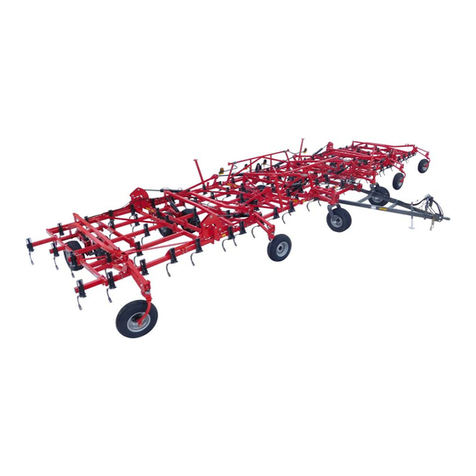
Figure 1.3. A QX2 Field Cultivator
Figure 1.3. B XL2 Field Cultivator

4000361195-00-en-na; 01.01.2024
Introduction
03
1.4 Machine Serial Number
Refer to Section 2.0 Safety on page 07 for more
information on the location of the safety decals and
the serial plate decal.
1.4.1 Serial Number Data Sheet
Record the machine model and serial number in the
spaces provided below. Use these numbers when
contacting the dealer for repair parts, warranty or
service assistance.
Figure 1.4.A Serial No. Decal
Serial Number(s)
Implement(s) Serial Range: 2320466136 - 2320466142, 2320466370
Implement Model Serial Number(s)
Cultivator
Other

4000361195-00-en-na; 01.01.202404
Introduction
1.5 Technical Data Sheet
1.5.1 XL2Field Cultivator
XL2(Level Lift Hitch)
Model 11 XL225 11 X L225-27 11 XL230-32 11 XL230-39 13 XL232 13 XL232-34 13 XL232-42
Number of Shanks 43 47 55 67 55 59 73
Cutting Width 25.1 ft
(7.6 m)
27.4 ft
(8.4 m)
32.1 ft
(6.4 m)
39.1 ft
(11.9 m)
32.1 ft
(6.4 m)
34.4 ft
(10.5 m)
42.6 ft
(13 m)
Inner Wing 7 ft (2.1 m) 7 ft (2.1 m) 9.3 ft (2.8 m) 9.3 ft (2.8 m) 9.3 ft (2.8 m) 9.3 ft (2.8 m) 9.3 ft (2.8 m)
Outer Wing 7 ft (2.1 m) 7 ft (2.1 m) 9.3 ft (2.8 m) 9.3 ft (2.8 m) - - 5 ft (1.5 m)
Number of Tires 8 8 10 12 10 10 12
Transport Width 16.1 ft (4.9 m) 16.1 ft (4.9 m) 16.1 ft (4.9 m) 16.1 ft (4.9 m) 18.4 ft (5.6 m) 18.4 ft (5.6 m) 18.4 ft (5.6 m)
Transport Height 10.4 ft
(3.2 m)
11.6 ft
(3.5 m)
13.8 ft
(4.2 m)
12.75 ft
(3.9 m)
12.75 ft
(3.9 m)
13.8 ft
(4.2 m)
13.4 ft
(4.1 m)
Weight 8,800 lbs
(3,992 kg)
9,000 lbs
(4,082 k g)
11,50 0 lbs
(5,216 kg)
13,500 lbs
(6,123 kg)
12,500 lbs
(5,670 kg)
12,700 lbs
(5,761 kg)
15,200 lbs
(6,895 kg)
Horsepower
Requirement 225 - 290 193 - 245 225 - 290 275 - 350 225 - 290 235 - 300 245 - 375
Chart 1.5.A Technical Data Sheet: XL2I
XL2(Level Lift Hitch)
Model 13 XL2
32-45 13 XL237 13 XL2
37-39
13 XL2
37-42
13 XL2
37-50
13 XL2
46-50 13 XL255 13 XL2
55-60
Number of Shanks 77 63 67 73 85 87 95 103
Cutting Width 44.9 ft
(13.7 m)
36.75 ft
(11.2 m)
39.1 ft
(11.9 m)
42.6 ft
(13 m)
49.6 ft
(15.1 m)
50.75 ft
(15.5 m)
55.4 ft
(16.9 m)
60.1 ft
(18.3 m)
Inner Wing 9.3 ft
(2.8 m)
11.7 ft
(3.6 m)
11.6 ft
(3.5 m)
11.7 ft
(3.6 m)
11.7 ft
(3.6 m)
9.3 ft
(2.8 m)
11.7 ft
(3.6 m)
11.7 ft
(3.6 m)
Outer Wing 6 ft (1.8 m) ---6 ft (1.8 m) 7 ft (2.1 m) 9.3 ft
(2.8 m)
9.3 ft
(2.8 m)
Number of Tires 12 10 10 10 12 16 16 16
Transport Width 18.4 ft
(5.6 m)
18.4 ft
(5.6 m)
18.4 ft
(5.6 m)
18.4 ft
(5.6 m)
18.4 ft
(5.6 m)
18.4 ft
(5.6 m)
18.4 ft
(5.6 m)
18.4 ft
(5.6 m)
Transport Height 13.4 ft
(4.1 m)
14.9 ft
(4.5 m)
15.9 ft
(4.8 m)
15.5 ft
(4.7 m)
15.5 ft
(4.7 m)
13.5 ft
(4.1 m)
15.5 ft
(4.7 m)
15.5 ft
(4.7 m)
Weight 15,400 lbs
(6,985 kg)
13,200 lbs
(5,987 kg)
13,400 lbs
(6,078 kg)
15,500 lbs
(7,031 kg)
16,200 lbs
(7,348 kg)
19,800 lbs
(8,981 kg)
20,800 lbs
(9,435 kg)
21,300 lbs
(9,662 kg)
Horsepower
Requirement 315 - 405 260 - 335 270 - 345 295 - 375 350 - 450 350 - 450 385 - 495 425 - 540
Chart 1.5.B Technical Data Sheet: XL2II

4000361195-00-en-na; 01.01.2024
Introduction
05
1.5.2 QX2Field Cultivator
QX2(Floating Hitch)
Model 13 QX232 13 QX232-34 13 QX232-42 13 QX232-45 13 QX237 13 QX237-39
Number of Shanks 55 59 73 77 63 67
Cutting Width 32.1 ft (6.4 m) 34.4 ft (10.5 m) 42.6 ft (13 m) 44.9 ft (13.7 m) 36.75 ft (11.2 m) 39.1 ft (11.9 m)
Inner Wing 9.3 ft (2.8 m) 9.3 ft (2.8 m) 9.3 ft (2.8 m) 9.3 ft (2.8 m) 11.7 ft (3.6 m) 11.6 ft (3.5 m)
Outer Wing --5 ft (1.5 m) 6 ft (1.8 m) - -
Number of Tires 12 12 14 14 12 12
Transport Width 18.4 ft (5.6 m) 18.4 ft (5.6 m) 18.4 ft (5.6 m) 18.4 ft (5.6 m) 18.4 ft (5.6 m) 18.4 ft (5.6 m)
Transport Height 12.75 ft (3.9 m) 13.8 ft (4.2 m) 13.4 ft (4.1 m) 13.4 ft (4.1 m) 14.9 ft (4.5 m) 15.9 ft (4.8 m)
Weight 13,500 lbs
(6,123 kg)
13,700 lbs
(6,214 kg)
16,300 lbs
(7,394 kg)
16,500 lbs
(7,484 kg)
14,300 lbs
(6,486 kg)
14,500 lbs
(6.577 kg)
Horsepower
Requirement 225 - 290 235 - 300 245 - 375 315 - 405 260 - 335 270 - 345
Chart 1.5.A Technical Data Sheet: QX2I
QX2(Floating Hitch)
Model 13 QX237-42 13 QX237-50 13 QX246-60 13 QX255 13 QX255-60
Number of Shanks 73 85 87 95 103
Cutting Width 42.6 ft (13 m) 49.6 ft (15.1 m) 50.75 ft (15.5 m) 55.4 ft (16.9 m) 60.1 ft (18.3 m)
Inner Wing 11.7 ft (3.6 m) 11.7 ft (3.6 m) 9.3 ft (2.8 m) 11.7 ft (3.6 m) 11.7 ft (3.6 m)
Outer Wing -6 ft (1.8 m) 7 ft (2.1 m) 9.3 ft (2.8 m) 9.3 ft (2.8 m)
Number of Tires 12 14 18 18 18
Transport Width 18.4 ft (5.6 m) 18.4 ft (5.6 m) 18.4 ft (5.6 m) 18.4 ft (5.6 m) 18.4 ft (5.6 m)
Transport Height 15.5 ft (4.7 m) 15.5 ft (4.7 m) 13.5 ft (4.1 m) 15.5 ft (4.7 m) 15.5 ft (4.7 m)
Weight 16,500 lbs
(7,484 kg)
17, 30 0 lbs
(7,847 kg)
20,500 lbs
(9,299 kg)
21,600 lbs
(9,798 kg)
22,000 lbs
(9,979 kg)
Horsepower
Requirement 295 - 375 350 - 450 350 - 450 385 - 495 425 - 540
Chart 1.5.B Technical Data Sheet: QX2II

4000361195-00-en-na; 01.01.202406
Introduction
1.6 General Information
Remove all wires and/or banding material. The parts
have been conveniently arranged on the pallet for
ease of assembly.
Always wear safety glasses/goggles, be careful
when cutting wires and steel bands as they are
under tension and will spring back when cut.
Lubricate all bearings and moving parts as you
proceed and make sure they work freely.
Loosely install all bolts connecting mating parts
before nal tightening.
When tightening bolts, they must be torqued to the
proper number (ft-lbs) as indicated in the table unless
specied. It is important that all bolts be kept tight.
On new machines, all nuts and bolts must be
rechecked after a few hours of operation.
Grade 2 Grade 5 Grade 8
Bolt Diameter 3/8” 1/2” 5/8” 3/4” 7/8” 1”
Hex Head 9/16” 3/4” 15/1” 1-1/8” 1-5/1” 1-1/2”
Torque (ft/lbs)
UNC GR2 18 45 89 160 252 320
UNC GR5 30 68 140 240 360 544
UNC GR8 40 100 196 340 528 792
UNF GR2 21 51 102 178 272 368
UNF GR5 32 70 168 264 392 572
UNF GR8 48 112 216 368 792 840
Chart 1.6.2. A Bolt Torques
When replacing a bolt, use only a bolt of the same
grade or higher. Except in shear bolt applications,
where you must use the same grade bolt.
Bolts with no markings are grade 2. Grade 5 bolts
furnished with the machine are identied by three
radial lines on the head.
Grade 8 bolts furnished with the machine are
identied by six radial lines on the head. All U-bolts
are grade 5.
CAUTION! Failure to follow these instructions
may result in personal injury and/or
equipment damage.
Just before and during operation be
sure no one is on or around the
implement.
Before activating the hydraulic
system, check hoses for proper
connections.
Before lowering the wings for the
rst time, make sure the entire
system has been charged with oil.
With wings down always install
hydraulic cylinder channel lock(s)
for transporting.

4000361195-00-en-na; 01.01.2024
Safety
07
2.0 Safety
2.1 Safety Alert Symbols
The Safety Alert Symbol(s) are intended to direct
the attention of the machine user to important
safety information both published in the Operator’s
Manual and applied to the machine. Any time
Safety Alert Symbol(s) are seen, it means that
associated information is provided for recognizing,
appropriately responding to and avoiding potentially
hazardous situation(s).
A triangle shape surrounding an exclamation
point indicates a potentially hazardous situation.
Information included in a safety sign or printed in
the Operator’s Manual describes the hazardous
situation and indicates appropriate response(s) and/
or avoidance procedures.
This Safety Alert Symbol means:
Attention Be Alert!
2.1.1 Signal Words
DANGER! Indicates an imminently hazardous
situation that, if not avoided, WILL result in
death or serious injury if the proper
precautions are not taken.
WARNING! Indicates a potentially hazardous
situation that, if not avoided, COULD result in
death or serious injury if the proper
precautions are not taken.
CAUTION! Indicates a potentially hazardous
situation that, if not avoided, MAY result in
minor or moderate injury if the proper
practices are not taken, or, serves as a reminder to
follow appropriate safety practices.
Used to clarify information.
The information next to this symbol may be
worth noting since it is a hint containing
particularly useful information on how to
handle the machine.
2.2 Safety Sign Information
Safety Sign Legibility: All safety signs applied to the
implement must be visible and legible. Keep dust
and dirt cleared from safety signs and ensure that
visibility is not obscured.
Safety Sign Replacement: Safety signs may be
ordered through the dealer or distributor.
For parts and decal replacement, contact
your local dealer parts department.
Damaged or Deteriorated Safety Signs: Remove
and replace any safety signs that have either been
damaged or show signs of deterioration.
Safety Signs on Replacement Parts: Ensure that parts
or components that are replaced on the implement
that had a safety sign attached originally include a
safety sign.
Afxing Safety Signs to the Implement
1. Ensure proper position and orientation before
installing.
2. Ensure installation area is clean and dry.
3. Ensure ambient temperature is above 10°C (50°F).
4. Remove backing material to expose label
adhesive.
5. Place one edge of label to machine surface.
6. Slowly press the label onto the surface.
7. Ensure no air pockets are present or become
trapped under surface or label. To remove air
pocket, pierce the bubble in the label with a pin,
this will let the trapped air out, and then press
the label down.

4000361195-00-en-na; 01.01.202408
Safety
2.3 Hand Signals
Hand signals are an important means of communication on farms where noise levels and distance can hinder
regular communication between workers. These 11 hand signals were created so that two or more persons
can communicate effectively and safely.
Lower Equipment: Make a circular
motion with either hand pointing to the
ground.
Raise Equipment: Make a circular motion
with either hand at head level.
Come to me: Raise the arm vertically
overhead, the palm to the front, and
rotate in large horizontal circles.
This far to go: Place palms at ear level
facing the head and move laterally
inward to indicate remaining distance
to go.
START THE ENGINE: Simulate cranking
of vehicles by moving arm in a circular
motion at waist level.
STOP THE ENGINE: Draw right hand,
palm down, across the neck in a ‘‘throat
cutting’’ motion from left to right.
Slow it down/decrease speed: Extend
the arm horizontally to the side, palm
down, and wave arm downward 45
degree minimum, repeat.
Speed it up/increase speed: Raise the
hand to the shoulder, st closed, thrust
the st upward to the full extent of the
arm and back to the shoulder rapidly,
repeat several times.
Move-Out: Face the desired direction of
movement, hold the arm extended to the
rear; swing it overhead, forward in the
direction of the desired movement until
it is horizontal, palm down.
Move toward me/follow me: Point toward
person(s), vehicle(s), or unit(s) beckon by
holding the arm horizontally to the front,
palm up, and motioning toward the body.
Stop: Raise hand upward to the full extent
of the arm, palm to the front. Hold that
position until the signal is understood.
To perform any/or all of these signals, stand
out of the pathway of the moving implement.
Diagram 2.3. A Hand Signals

4000361195-00-en-na; 01.01.2024
Safety
09
2.4 Operator
Responsibilities
Responsibility for the safe operation, adjustment,
maintenance and repair of this machine falls to the
main user. It is the responsibility of the owner, or
authorized person in charge, to ensure all persons
who operate, adjust, maintain and/or repair this
implement be familiar with the information provided
in this Operator’s Manual before performing any
other tasks listed above.
A safe user is the key to safety. Good safety practices
not only protect the user, but also persons who may
be in the vicinity of the implement. Make good safety
practices a part of the farming operation. Ensure
that all persons operating, adjusting, maintaining
and/or repairing this implement are familiar with
the procedures recommended in this manual.
Always read safety warnings and follow recommended
safety precautions to avoid hazardous situations.
DO NOT risk personal injury or death by ignoring
safety warning and safety precautions.
2.4.1 Key Safety Reminders
The most important safety device is a safe and
qualied user.
A safe and qualied user is one who has read and
understands the contents of the Operator’s Manual
prior to performing any tasks related to the machine.
Owners have a responsibility to provide training to
persons who may operate, adjust, maintain and/
or repair the implement prior to performing any of
these tasks.
DO NOT perform any unauthorized modications to
the implement or use the implement for any purpose
other than what is described in the contents of this
Operator’s Manual.
QX2/XL2owners must give operating instructions
to operators and employees before allowing them
to operate the eld cultivator, and at least annually
thereafter per OSHA regulation 1928.57.
2.5 General Safety Practices
Read and understand the contents of this Operator’s
Manual prior to operating, adjusting, maintaining
and/or repairing the implement.
Locate, read and understand all safety signs applied
to the implement before performing any tasks.
Review the contents of this Operator’s Manual
at least annually, and, any time a new person is
assigned to perform any tasks with the implement.
Ensure that all bystanders, especially small children,
and pets/animals are kept at a safe distance while
performing any tasks with the implement.
WARNING! DO NOT allow riders on any part
of the implement.
Ensure all guards and shields are intact and in place
prior to operating the implement.
Keep hands, feet, hair and loose clothing away from
moving and/or rotating parts.
Stop the engine, lower the implement, set the parking
brake, remove the ignition key, and allow time for
moving parts to stop prior to adjusting, maintaining,
and/or repairing the implement.
Ensure that all implement lighting and marking is
intact, secure, clean and operating properly prior to
traveling on public roads. Check with local highway
authorities to conrm implement is properly
equipped for highway travel.
Provide a fully stocked First-Aid Kit in a highly
visible and easily accessible location.
Ensure a re extinguisher is available for use should
the need arise and that the operator is familiar with
its proper use.
Clear the implement of any and all foreign objects
before beginning operation.

4000361195-00-en-na; 01.01.202410
Safety
Ensure that implement is securely blocked and
supported prior to working underneath.
Do not work with the machine during thunderstorms
and when there is a risk of lightning strikes. Do not
stand on or next to the machine.
Always wear suitable ear protection for prolonged
exposure to excessive noise.
2.6 Maintenance Safety
Read and understand all information provided in the
Operator’s Manual covering operation, adjustment,
maintenance and repair prior to performing any
of these tasks. Plan work to ensure proper tools,
equipment, and personal protective equipment is
available prior to working on implement.
Wear appropriate clothing when performing tasks
around implement. Ill-tting and/or frayed clothing
as well as loose or dangling items should not be
worn when working near the implement.
Stop the engine, lower the implement, set the parking
brake, remove the ignition key, and allow time for
moving parts to stop prior to adjusting, maintaining,
and/or repairing the implement.
Ensure that all moving parts have come to a complete
stop before performing adjustments, maintenance
and/or repairs.
Ensure that hydraulic oil pressure in hoses, lines,
and components is fully relieved prior to performing
any maintenance, and/or repairs.
Ensure that wings are either fully lowered or fully
raised and secured with their safety chains and
pins or securely block the wings if raised to perform
adjustments, maintenance and/or repairs.
Securely block main frame and/or wings if
adjustments, maintenance, and/or repairs are
required for wheels and tires.
Wear personal protective equipment, such as gloves,
eye protection, etc. when inspecting the hydraulic
system for leaks. Use a small piece of cardboard or
wood to detect leaks.
Ensure that all guards and shields are intact and in
place after performing adjustments, maintenance
and/or repairs prior to operating implement.
Store ammable uids in approved containers
and store out of access by unauthorized persons,
especially children.
Replace the safety chain if one or more links or end
ttings are broken, stretched or otherwise damaged
or deformed.
2.7 Hydraulic Safety
Always place all tractor hydraulic controls in neutral
before dismounting.
Ensure that all hydraulic system components are
kept clean and in proper working condition.
Relieve pressure before working on hydraulic
system.
Use a piece of cardboard or wood to check for
hydraulic leaks.
Wear personal protective equipment, such as
gloves, eye protection, etc. if unsure if residual
pressure may exist in hydraulic components during
troubleshooting and/or making repairs.
If injured by a concentrated high-pressure stream of
hydraulic uid, seek medical attention immediately.
Serious infection or toxic reaction can develop from
hydraulic uid piercing the skin surface.
Check hydraulic hoses regularly for wear and
replace as needed. Contact your local Dealer
parts department to purchase replacement hoses
specically designed for Wil-Rich machines.

4000361195-00-en-na; 01.01.2024
Safety
11
DO NOT attempt any makeshift repairs to the
hydraulic lines, ttings or hoses by using tape,
clamps or cements. The hydraulic system operates
under extremely high-pressure. Such repairs will
fail suddenly and create a hazardous and unsafe
condition.
Always contact the nearest Wil-Rich dealer or
service professional when replacing hydraulic
hoses.
When replacing hoses always route hoses the same as
the one being replaced to ensure that the part is not
subjected to wear, rubbing, kinking, etc. Make repairs
following instructions provided by the manufacturer.
Ensure all ttings, couplings, and other hydraulic
connections are intact and properly tightened
before operating implement hydraulic system.
WARNING! DO NOT touch pressurized hose
assembles with any part of the body. If uid
punctures the skin, seek immediate medical
attention.
Hydraulic uids are highly ammable. Always
keep open ames and ignition sources away from
hydraulic uids.
In all cases, hydraulic lines and/or electrical
cables used to operate the towed machines
braking system, if so equipped, shall have
more slack than the auxiliary attaching system so that
if a failure of the primary attaching system should
occur, trailer braking shall still be possible.
2.8 Electrical Safety
Ensure that the machinery is shut off and all
electrical components are disconnected before
doing any work on the machine. Ensure all live
connections are not receiving power.
Check electrical wires regularly for wear related to
usage and weathering. Replace any damaged wires
or components immediately.
Use insulated tools whenever performing service
to any electrical system or components and always
wear proper protective equipment.
2.9 Transport and Towing
Safety
Read and understand ALL the information in the
Operator’s Manual regarding procedures and
SAFETY when moving the cultivator in the eld/
yard or on the road.
WARNING! DO NOT allow riders on any part
of the implement.
Ensure that implements are attached to tractor
properly.
Ensure draw-bar hitch pin retainer is in place and
functioning properly.
Ensure safety tow chain is securely attached and
retaining clip is securely locked in place.
Ensure the ladder/stairs is securely fastened based
on the model and corresponding procedure outlined
in the Procedures section of this manual.
Ensure all lighting and implement marking devices
are intact and visible.
Ensure implement is properly marked according to
local road regulations.
Read and follow all local road trafc regulations.
DO NOT exceed 20 mph (30 km/h). Tires are
not rated for speeds higher than 20 mph
(30 km/h). The axles, casters, and wheel
hubs are not designed for high speed use.
Turn on ashing warning (hazard) lights whenever
traveling on a highway, except where such use is
prohibited by law.

4000361195-00-en-na; 01.01.202412
Safety
Make sure SMV (Slow Moving Vehicle) emblem and
all lights and reectors that are required by the local
highway and transport authorities are in place, are
clean and can be seen clearly by all overtaking and
oncoming trafc.
Keep to the right and yield the right-of-way to allow
faster trafc to pass. Drive on the road shoulder, if
permitted by law.
Always use hazard warning ashers on tractor when
transporting unless prohibited by law.
Components that are retracted to decrease the width
for highway transport have means to positively
secure those components during highway transport.
One or more types of locking systems may be used.
Examples of locking systems are hydraulic cylinder
locks and folding over-center.
2.10 Storage Safety
Store the implement away from areas of human
activity.
WARNING! DO NOT allow children to play on
or around the implement(s).
Store the implement on a dry, stable, and level
surface. Support with planks if required.
2.11 Tire Safety
Ensure tire ination pressure is maintained per
specications.
Do not attempt to mount a tire unless you have the
proper equipment and experience to do the job.
Follow proper procedures for tire repairs, especially
when mounting tire to the rim.
Seek assistance from a trained person for tire repairs
or mounting, especially if specialized equipment is
required.
2.12 Hazards
The key is to recognize hazards while working or
living on a farm; avoid dangerous situations or at
least minimize the exposure to them.
This section deals with danger points on agricultural
equipment; those areas which can entangle, pinch,
crush, or shear clothing and limbs. Possible danger
points could be wing fold points, hydraulic cylinders
and hydraulic lines on many types of equipment.
A slow-moving hydraulic arm can be as hazardous
as a rapidly rotating power take-off shaft.
Recognize the dangers!
The rst step to avoiding danger is to recognize
that hazards exist. Refer to 2.0 Safety on page 07.
Identify the specic hazards associated with the
equipment.
The next step is to consider how to use the
equipment. Using it for tasks it was meant to perform?
Following all safety precautions recommended by
the manufacturer?
Most machinery accidents result from human
error. The operator either forgot something, took
a shortcut, ignored a warning, wasn’t paying close
attention, or failed to follow safety rules. Be familiar
with the operator manual, know the limitations
of the equipment, and follow safety measures
automatically.
Carefully evaluate the operation of each implement
for safety before starting work.
Check equipment guards.
Check guards on all equipment as part of a routine
maintenance schedule. During seasons when
equipment is used heavily, check guards more often.
Equipment guards cannot eliminate all injuries.
A transport lock will only work if it is engaged prior
to road transport, and will not prevent accidents if
it is not engaged.

4000361195-00-en-na; 01.01.2024
Safety
13
Recognize secondary hazards.
Many farm injury victims recognize hazardous
situations, but they misjudge the seriousness of the
hazard because of secondary factors.
For example, spilled grain or debris in an unloading
area could cause someone to slip and fall into
the intake auger. Icy, muddy, or manure-covered
surfaces make the work area slick and increase the
risk of injury. Bystanders or children in the work
area can distract the operator, or limit operator
vision.
High pressure hydraulic oil is a major hazard. Any
leaks in the hydraulic system must be treated as
a dangerous situation and should be dealt with
accordingly.
Consider human factors.
Farm operators can overestimate their ability to
stop or avoid a dangerous situation. This is common
when operators work around powerful equipment
every day and become comfortable with their ability
to control the machinery.
Operators are also limited by their reaction time.
Human reaction time is not quick enough to avoid
an injury with machinery.
Gravity as well is faster than human reaction. For
example, it is very dangerous to reach underneath
the wing of a machine if the transport/safety locks
are not correctly in place. If a hydraulic line breaks,
gravity could pull the machine wings to the ground
very quickly, crushing the operator.
Manufacturers have built safeguards into equipment
but all hazards cannot be removed. Take a realistic
approach to equipment safety and think about these
principles for the operation of all machinery.
• Be aware of the dangers. Read the operator
manuals and think about how to use the
equipment.
• Regularly repair and replace protective guards
or shields on all implements.
• Look for and remove secondary hazards, such
as spilled grain or debris.
• Recognize the limitations of the user and the
equipment.
Farm machinery safety: What to do?
• A few simple actions can reduce the risk of
danger around farm machinery.
• Collect operator manuals for all farm equipment
and place in a central location. Read the safety
section in each manual.
• Evaluate how to anticipate using each implement
and identify potential safety hazards not
mentioned in the manual.
• Check condition of intake guards and shields on
grain augers and other implements.
• Remove debris from grain unloading areas.
Shut down equipment when other people enter
the area.

4000361195-00-en-na; 01.01.202414
Safety
2.13 Safety Signs 2.13.1 Location of Safety Signs
22371 RED REFLECTOR
22372 AMBER
REFLECTOR
54900 WINGS UP DECAL
54901 WINGS DOWN DECAL
54902MAIN UP DECAL
49163 WING LOCK DANGER DECAL
2012 INTEGRAL
RESTRICTOR DECAL
49165 CAUTION DECAL
CAUTION
TO AVOID INJURY AND/OR MACHINE DAMAGE:
Refer to Operator's Manual for safety instructions.
Do not stand or climb on machine when operating.
Use clean hazard ashers and SMV sign when
transporting.
Observe highway trac regulations.
23325
23325 CAUTION DECAL - READ
Diagram 2.13.1. A QX2Safety Signs I
1
23
4
7
7
Refer to Section 2.13.2 Decals on page 18.
Safety
Other manuals for QX2
2
This manual suits for next models
4
Table of contents
Other WIL-RICH Tiller manuals