WIL-RICH QX2 User manual

QX2ASSEMBLY MANUAL 74304 1/11
1
FIELD CULTIVATOR
ASSEMBLY INSTRUCTIONS
WIL-RICH
PO Box 1030
Wahpeton, ND 58074
PH (701) 642-2621
Fax (701) 642-3372
www.wil-rich.com
Printed in USA (74304) 1/2011

QX2ASSEMBLY MANUAL 74304 1/11 2
WARRANTY
The only warranty Wil-Rich gives and the only warranty the dealer is authorized to give is as
follows:
We warrant products sold by us to be in accordance with our published specifications or those
specifications agreed to by us in writing at time of sale. Our obligation and liability under this
warranty is expressly limited to repairing, or replacing, at our option, within 12 months after date of
retail delivery, any product not meeting the specifications. We make no other warranty, express
or implied and make no warranty of merchantability or of fitness for any particular purpose.
Our obligation under the warranty shall not include any transportation charges or costs or installa-
tion or any liability for direct, indirect or consequential damage or delay. If requested by us, products
or parts for which a warranty claim is made are to be returned transportation prepaid to our factory.
Any improper use, operation beyond rated capacity, substitution of parts not approved by us, or any
alteration or repair by others in such manner as in our judgment affects the product materially and
adversely shall void this warranty. No employee or representative is authorized to change this
warranty in any way or grant any other warranty.
Wil-Rich reserves the right to make improvement changes on any of our products without notice.
When warranty limited or not applicable: Warranty on hoses, cylinders, hubs, spindles, engines,
valves, pumps or other trade accessories are limited to the warranties made by the respective
manufactures of these components. Rubber tires and tubes are warranted directly by the respec-
tive tire manufacturer only, and not by Wil-Rich.
Warranty does not apply to any machine or part which has been repaired or altered in any way so
as in the our judgment to affect its reliability, or which has been subject to misuse, negligence or
accident.
A Warranty Validation and Delivery Report Form must be filled out and received by Wil-Rich
to initiate the warranty coverage.
WARRANTY CLAIMS PROCEDURE
1. The warranty form must be returned to Wil-Rich within fifteen (15) working days from the repair
date.
2. Parts returned to Wil-Rich without authorization will be refused. The parts must be retained at
the dealership for ninety (90) days after the claim has been filed. If the Service Department would
like to inspect the parts, a packing slip will be mailed to the dealer. The packing slip must be returned
with the parts. The parts must be returned prepaid within thirty (30) days of receiving authorization.
After the parts are inspected and warranty is verified, credit for the return freight will be issued to
the dealer.
3. Parts that will be scrapped at the dealership will be inspected by a Wil-Rich Sales Representa-
tive, District Sales Manager or Service Representative within the ninety (90) day retaining period.

QX2ASSEMBLY MANUAL 74304 1/11
3
ALL PERSONNEL INVOLVED WITH THE ASSEMBLY AND/OR OPERATION OF THIS
EQUIPMENT MUST BE INFORMED OF PROPER SAFETY PROCEDURES. OPERATOR’S/
ASSEMBLY MANUALS PROVIDE THE NECESSARY INFORMATION. IF THE MANUAL IS
LOST FOR A PARTICULAR IMPLEMENT, ORDER A REPLACEMENT AT ONCE.
OPERATOR’S AND ASSEMBLY MANUALS ARE AVAILABLE AT NO CHARGE UPON RE-
QUEST.
PERSONAL SAFETY IS IMPORTANT!
ADDRESS INQUIRIES TO: WIL-RICH PO BOX 1030
WAHPETON, ND 58074
PH (701) 642-2621 FAX (701) 642-3372
This Safety Alert symbol
means ATTENTION! BE-
COME ALERT YOUR
SAFETY IS INVOLVED!
The Safety Alert symbol iden-
tifies important safety mes-
sages on the Wil-Rich Quad X
Field Cultivator and in this
manual. When you see this
symbol, be alert to the possi-
bility of personal injury or death.
Follow the instructions in the
safety message.
Why is SAFETY important to you?
3 Big Reasons Accidents Disable and Kill
Accidents Cost
Accidents Can Be Avoided
SIGNAL WORDS:
Note the use of the signal
words DANGER, WARNING
and CAUTION with the safety
messages. The appropriate
signal word for each message
has been selected using the
following guidelines:
DANGER
An immediate and spe-
cific hazard which WILL
result in severe personal
injury or death if the
proper precautions are
not taken.
WARNING
A specific hazard or un-
safe practice which
COULD result in severe
personal injury or death
if the proper precautions
are not taken
CAUTION
Unsafe practices which
COULD result in per-
sonal injury if proper
practices are not taken,
or as a reminder of good
safety practices.

QX2ASSEMBLY MANUAL 74304 1/11 4
CONTENTS
GENERAL INFORMATION .......................................... 5
TRANSPORT SAFETY .................................................. 6
ASSEMBLY
OPENING BUNDLE ....................................................7-8
AXLESAND WALKING TANDEMS ............................. 9
MAINFRAME .............................................................. 10
HITCHASSEMBLY ...................................................... 11
HITCHASSEMBLY CONTINUED ............................... 12
7’, 9’4”, & 11’8” WINGS ............................................ 13
3’ OUTER WING .......................................................... 14
5’FLOATING OUTER WINGW/GAUGE WHEEL ...... 15
6’FLOATING OUTER WINGW/GAUGE WHEEL ...... 16
WING LIFT COMPONENTS ....................................... 17
OUTER WING HYDRAULIC GAUGE WHEEL ............ 18
HYDRAULICS-OUTER GAUGE WHEEL .................... 19
PARALLELLINK GAUGE WHEELS ........................... 20
DEPTH INDICATOR .................................................... 21
SINGLE POINT DEPTH CONTROL ........................... 22
SINGLE POINT HANDLE ............................................ 23
CHECKVALVE ............................................................. 24
CHECK VALVES .......................................................... 25
HOSE CLAMP ............................................................. 26
LIFT HYDRAULICS
QX227 ................................................................. 27
QX232 ................................................................. 28
QX237 ................................................................. 29
WING FOLD HYDRAULICS
QX227 ................................................................. 30
QX232 & 37 ....................................................... 31
QX232 & 37 W/OUTERWINGS ..................... 32
CHARGING LIFT SYSTEM ......................................... 33
CHARGING WING FOLD SYSTEM ............................ 34
OPTIONAL- HYD WEIGHT BALANCE KIT .............. 35
BLANK PAGE FOR NOTES ........................................ 36
TWIN SPRING SHANK ASSEMBLY ............ 37
SINGLE SPRING SHANK ASSEMBLY ........ 38
SHANK PLACEMENTS
13’ MAIN FRAME ........................................... 39
7’ WING .............................................................. 40
9’ 4” WING ................................................................... 41
11’8” WING ................................................................. 42
2' OUTER RIGID STUB & 3’ OUTER WIN ................. 43
5' OUTER WING .......................................................... 44
6’ OUTER WING .......................................................... 45
OPTIONAL- HDAUXILIARYHITCH ......................... 46
LIGHTS ........................................................................ 47
SAFETY DECALS .................................................. 48-49
BLANK PAGE FOR NOTES ........................................ 50

QX2ASSEMBLY MANUAL 74304 1/11
5
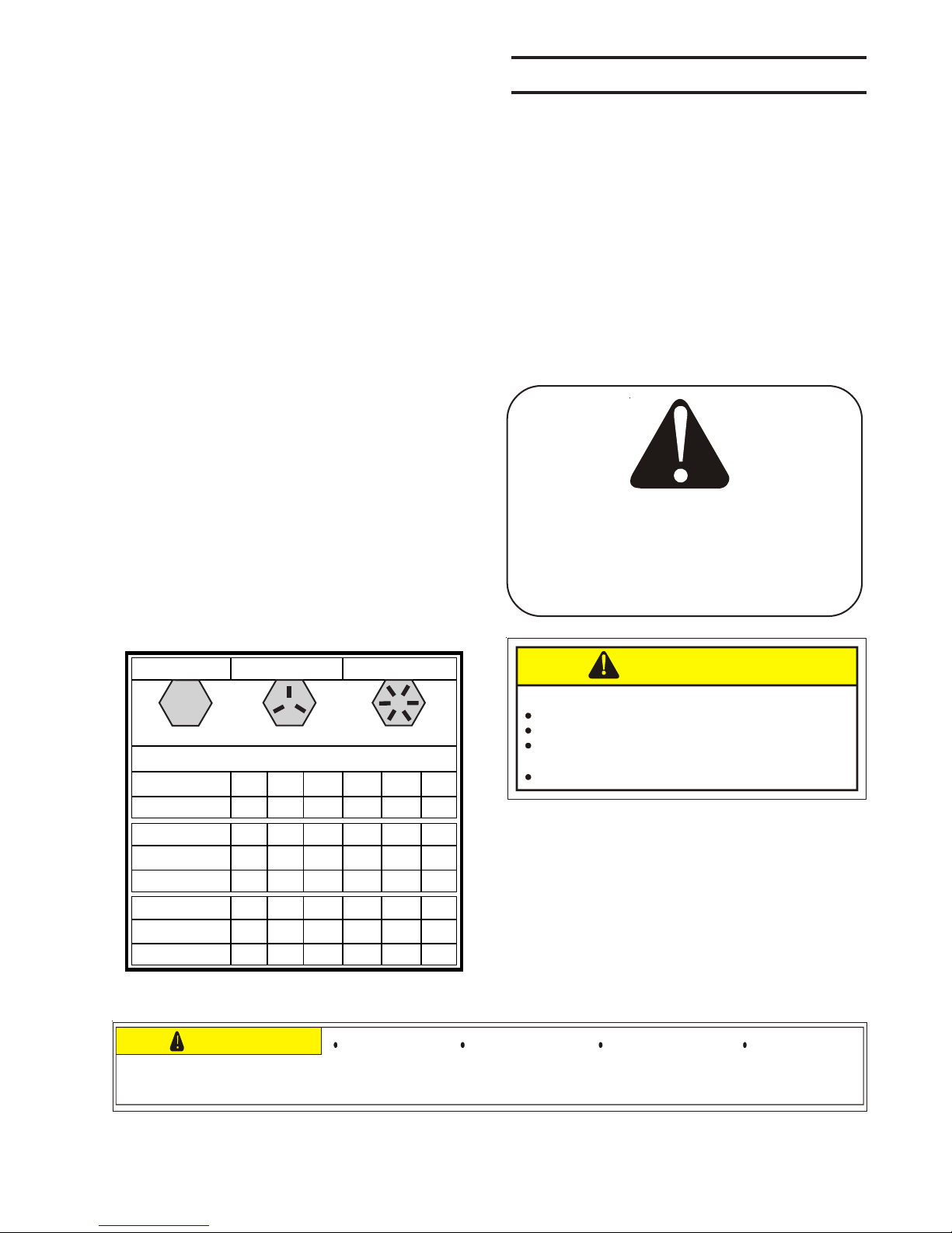
GRADE 2 GRADE 5 GRADE 8
TORQUE IN FOOT POUNDS
BOLT DIA 3/8 1/2 5/8 3/4 7/8 1
HEX HEAD 9/16 3/4 15/16 1-1/8 1-5/1 1-1/2
UNC GR2 18 45 89 160 252 320
UNC GR5 30 68 140 240 360 544
UNC GR8 40 100 196 340 528 792
UNF GR2 21 51 102 178 272 368
UNF GR5 32 70 168 264 392 572
UNF GR8 48 112 216 368 792 840
When replacing a bolt, use only a bolt of the
same grade or higher. Except in shear bolt
applications, where you must use the same
grade bolt.
Bolts with no markings are grade 2
Grade 5 bolts furnished with the machine are
identified by three radial lines on the head.
Grade 8 bolts furnished with the machine are
identified by six radial lines on the head.
All U-bolts are grade 5.
THIS SYMBOL USED TO CALL YOUR ATTEN-
TION TO INSTRUCTIONS CONCERNING YOUR
PERSONAL SAFETY.
BE SURE TO OBSERVE AND FOLLOW THESE
INSTRUCTIONS
Remove all wires and arrange the parts con-
veniently.
NOTE: Always wear safety glasses or
goggles and be careful when cutting wires
and steel bands as they are under tension and
will spring back when cut.
Wherever the terms "left" and "right" are used,
it must be understood to mean from a posi-
tion behind and facing the machine.
Lubricate all bearings and moving parts as
you proceed and make sure they work freely.
Loosely install all bolts connecting mating
parts before final tightening.
When tightening bolts, they must be torqued
to the proper number of foot-pounds as indi-
cated in the table unless specified. It is im-
portant that all bolts be kept tight.
On new machines, all nuts and bolts must be
rechecked after a few hours of operation.
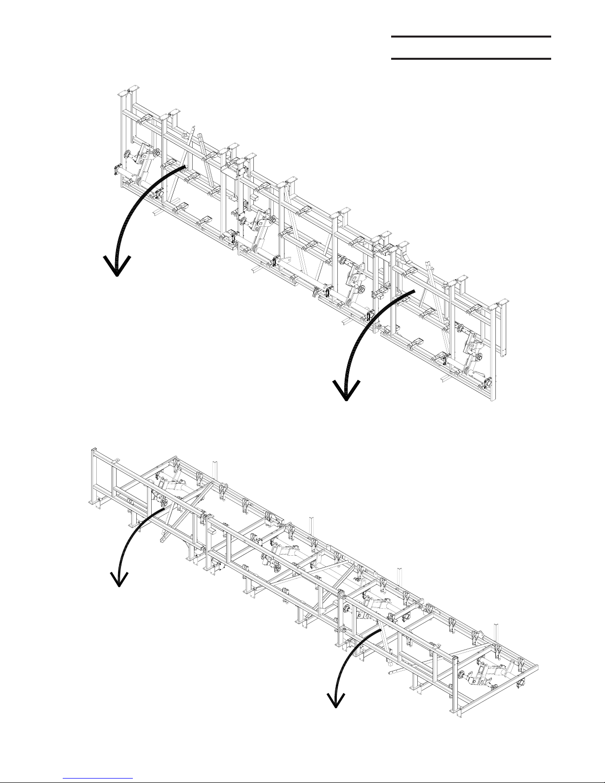
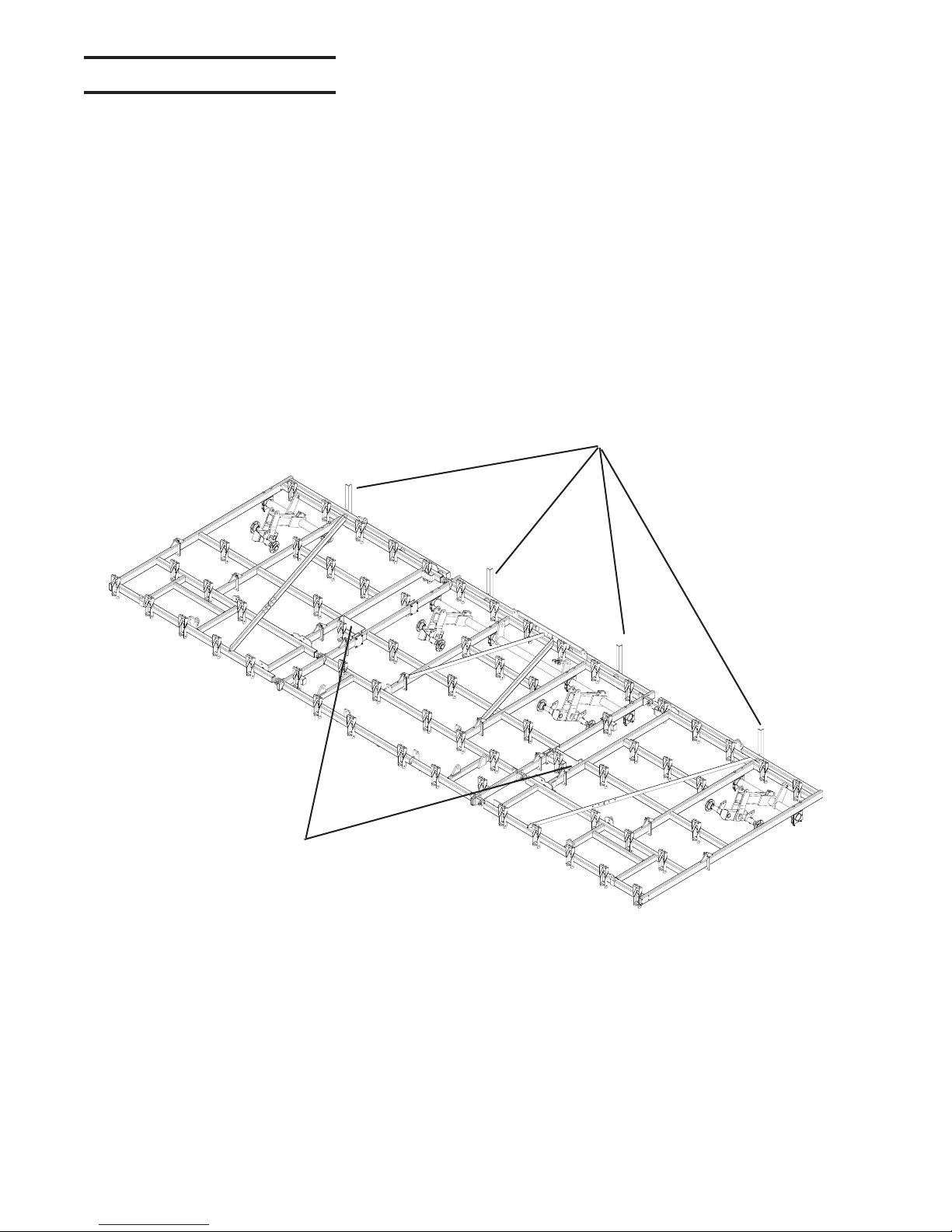
ASSEMBLY INFORMATION
Refer to Operator's Manual for safety instructions.
Do not stand or climb on machine when operating.
Use clean hazard flashers and SMV sign when
transporting.
Observe highway traffic regulations.
TO AVOID INJURY AND/OR MACHINE DAMAGE:
CAUTION
23325
FAILURE TO FOLLOW THESE
INSTRUCTIONS MAY RESULT IN PERSONAL
INJURY AND/OR EQUIPMENT DAMAGE.
CAUTION
53334
Just before and during
operation be sure no one is
on or around the
implement.
Before activating the
hydraulic system, check
hoses for proper
connections.
With wings down always
install hydraulic cylinder
channel lock(s) for
transporting.
Before lowering the wings for
the first time, make sure the
entire system has been charged
with oil.
MODIFICATIONS
It is the policy of Wil-Rich to improve its prod-
ucts whenever possible and practical to do so.
We reserve the right to make changes, im-
provements and modifications at any time
without incurring obligation to make such
changes, improvements on any equipment
sold previously.

QX2ASSEMBLY MANUAL 74304 1/11 6
SAFETY The safety chain should be hooked long
enough to permit full turns. Unnecessary slack
should be taken up.
Intermediate support is to be used if there is
more than 6" of unsupported chain on either
side of the primary attaching point.
The intermediate support should not be
mounted more than 6" from the primary at-
taching point. (See figure below)
The intermediate support is available from
your Wil-Rich dealer.
SMV MOUNTING BRACKET
SMV EMBLEM
NYLON TIE WRAP
CI-77643
The bracket provided is designed to mount to
numerous frame sizes and can be orientated
in different positions to avoid interference with
implement components.
The SMV emblem is to be secured as near to
the rear and centered, or as near to the left of
center of implement as practical.
Emblem is to be 2 to 6 feet above the ground
measured from the lower edge of the emblem.
Keep safety decals clean. Replace any safety
decals that are damaged, destroyed, miss-
ing, painted over or can no longer be read.
Replacement safety decals are available
through your dealer.
The purpose of the safety chain is to provide
an auxiliary attaching system to retain the con-
nection between towing and towed machine
in the event of separation of the primary at-
taching system.
1/4NCx3/4 BOLT
SAFETY CHAIN
CLEVIS END TO
TRACTOR
SAFETY CHAIN
MOUNT
CI-77825
PRIMARYATTACHING POINT
INTERMEDIATE
SUPPORT
6" MAX

QX2ASSEMBLY MANUAL 74304 1/11
7
OPENING BUNDLE
Step #1
Lay bundle down, supporting frame securely
36 to 40 inches off the ground.
Step #2
Unfold front frame and bolt into place using
3/4x2 inch grade 8 bolts as shown on main
frame and wing assembly pages.

QX2ASSEMBLY MANUAL 74304 1/11 8
OPENING BUNDLE
Step #3
After bundle is unfolded and the two frame
halves are bolted together remove shipping
stands and brackets.
After the shipping stands and brackets are
removed the rest of the cultivator may be as-
sembled as shown in this book.
Remove
shipping stands
Remove
shipping brackets

QX2ASSEMBLY MANUAL 74304 1/11
9
MAIN AXLE & WALKING TANDEM
79144.PLT
NOTE: WING WALKING
TANDEM COMPONENTS
ARE THE SAME AS THE
MAIN AXLE WALKING TAN-
DEM.
WHEEL ASSY
2” HUB &
SPINDLE
(14131)
1/2NFx3-1/4 GR5
BOLT
(88429)
3/4NCx2-3/4 GR5
BOLT
(88841)
AXLE ANCHOR
(220769)
PIN 1x6-3/8
(68033)
1” FLAT
WASHER
(88196)
ROLL PIN
1/4x2-1/4
(42484)
AXLE & WALKING TANDEM 7’, 9’4” & 11’8” WING
PIN 1x6-3/8
(68033)
1” FLAT
WASHER
(88196)
ROLL PIN
1/4x2-1/4
(42484)
3/4NCx2-3/4 GR5
BOLT - (88841)
WING AXLE ASSY
LH - (220782)
RH - (220781)
10.8 WING
MASTANCHOR
(221261)
19-7/8
LK NUT 1/2NF
(88304)
10.8 MAST ANCHOR
(221261)

QX2ASSEMBLY MANUAL 74304 1/11 10
WING REST (240818)
MUST BE MOUNTED
BEFORE MAST TUBE
5/8NCx3x5-1/4
U-BOLT
(88503)
1/4x2-1/4
SPIRAL PIN
(42484)
3/4NCx2
GR8 BOLT
(88290)
QUADX MAIN MAST TUBE
(221461)
MAIN FRAME
QUADX AXLE ANCHOR
(220769)
3/4NC X 2-3/4
GR5 BOLT
(88841)
CLEVIS
ADJUST
ROD
(54800)
1-1/4 FLAT
WASHER
(88440)
TUBE PIN
1-1/4 X 3-3/8
(68034)
SEE PAGE 20 FOR
COMPONENT LIST
3/4NCx6 GR5
(88293) 1-1/4NC JAM NUT
(88622)
NOTE - ORIENTATION
GAUGE WHEEL
LOCATION
NOTE: OFFSET ANCHOR
ON ARM, RIGHT SHOWN,
LEFT IS OPPOSITE
ASSY HDWR
74304-1

QX2ASSEMBLY MANUAL 74304 1/11
11
79149-3-2006
HITCH ASSEMBLY
RUBBER
EDGING
(236092)
3/16x2 COTTER
PIN
(88133)
UTILITY POLE
(236142)
TUBE-OPERATORS
MANUAL
(234313)
3/8x6x4-3/4
U-BOLT
(89069)
TUBE HOLDER
(234313)
1/4NCx1 GR5
BOLT
(88203)
LIGHT PLUG
RETAINER
(223329)
1/4NCx3/4 GR5
BOLT
(88993) 5/8NCx2 GR5
BOLT
(88294)
3/4NCx6 GR5
BOLT
(88293)
4 HOLE PLATE
(3-3/4x4-11/16)
DIAMOND
(68040)
LEFT HITCH TUBE
(220796)
HITCH
(221445)
HITCH TUBE-
(220792)
RIGHT HITCH TUBE
(220795)
HITCH BOLT
(11638)
SAFETY CHAIN
(24459)
JACK
(24415)
DUAL HITCH
(18236)
3/8 FLAT
WASHER
( 88282)
3/8 LOCK
WASHER
(88362)
3/8 HEX NUT
(88103)
1-1/4NC
SLOTTED
NUT
(88350)
1-1/4NCx6-1/2 GR5
BOLT
(88349)
1-1/4NC JAM
NUT
(88622)
ASSY HDWR
74304-2 NOTE: ASSEMBLE ALL
RIGHT, LEFT AND CEN-
TER HITCH TUBE BE-
FORE TIGHTENING

QX2ASSEMBLY MANUAL 74304 1/11 12
HITCH ASSEMBLY CONTINUED
SAFETY CHAIN
(24459)
JACK
(24415)
3/8NCx5x4 U-
BOLT (89069)
3/8 FLAT
WASHER
(88282)
3/8 LOCK
WASHER
(88362)
3/8NC HEX
NUT
(88103)
HITCH BOLT
(11638)
DUAL HITCH
(18236)
1-1/4 SLOTTED
NUT (88350)
3/16x2 COTTER
PIN (88133)
1/4 FLAT
WSAHER
(88261)
1/4NCx3/4
GR5 BOLT
(88993)
TUBE &
TUBE
HOLDER
(234313)
UTILITY
POLE
(236142)
LIGHT PLUG
RETAINER
(223329)
1/4 LOCK
WASHER
(88262)
1/4 NC NUT
(88172)
1/4NCx1 GR5
BOLT (88203) RUBBER
EDGING
(236092)
700160

QX2ASSEMBLY MANUAL 74304 1/11
13
79143-3-2006.DWG
BOLT PLATE
(65688)
1/2NCx3-1/2
GR5 BOLT
(88507)
6-1/2” SHANK STUB
(68021)
PIN (1-1/4x2.88)
(68034)
1/4X2-1/4
ROLL PIN
(42484)
MACHINERY BUSHING
(1-1/4x1.78x14 GA.)
(88440)
1X3-7/8 PIN
(221714)
1NCx6
GR5 BOLT
(88264)
ADJUSTER ROD
(9.5)
(69799)
AXLE CLAMP ASSY
(34132)
3/4NCx13 GR5 BOLT
(89165)
AXLE CLAMP ASSY
(34132)
WING
ADJUST
ARM
(67709)
1NC NYLON
LOCK NUT
(89075)
1NCx6GR5 BOLT
(88264)
7’, 9' 4”AND 11’8” WING
11’8” LEFT WING
(SHOWN)
1/4X2-1/4 ROLL PIN
(42484)
1 FLAT
WASHER
(88196)
GAUGE TUBE
ADJUST BRACKET
(220843) 1NCX8
ADJUSTMENT
ROD
(48890)
3” ANGLE IRON
TO ANGLE IRON
1NC NUT(3)
(88125
WING TUBE
(221504)
3/4NC X 2-3/4
GR5 BOLT
(88841)
SEE PAGE 17 FOR
COMPONENT LIST
10.8 MAST ANCHOR
(221261)
1-1/4NC
JAM NUT
(88622)
TIGHTEN JAM
NUT TO BACK
OF ADJUST
EAR
5-1/2” TUBE
TO PLATE
ALIGN GAUGE WHEELAN-
CHOR WITH WING ADJUST
TUBE & WING AXLE ANCHOR
SEE PAGE 20 FOR
COMPONENT LIST
5/8NCx1-1/2
GR5 BOLT
(88577)
ASSY HDWR
74304-3

QX2ASSEMBLY MANUAL 74304 1/11 14
79146
3FT OUTER WING - RIGHT
(67924)
3FT OUTER WING - LEFT
(67925)
5/8NCx3-1/2
GR5 BOLT
(88292)
1NC LOCK NUT
(89075)
1NCx6 GR5 BOLT
(/88264)
5/8NCx3x5-1/4 U-BOLT
(88503)
EXC OUTER WING REST
(68066)
PLATE
(67934)
1NCx5 GR5 BOLT
(88312)
LINKAGE ARM
(67903)
SPIROL PIN
(42844)
PIN (1x3-1/4)
(42472)
1 FLAT WASHER
(88196)
SHIM
(51469)
1/2NCx1-1/2 GR5
BOLT
(88475)
EXC WING HINGE
RH- (68023)
LH- (68024)
1NCx5 GR5 BOLT
(88312)
5/8NCx3x5-1/4 U-BOLT
(88503)
1NC LOCK NUT
(89075)
1NC LOCK NUT
(89075)
3' OUTER WING
HINGE AREA
TOP VIEW
37-3/16”
NOTE: POSITION WING REST TO CONTACT
OUTER TUBE WHEN FOLDED.
NOTE: DO NOT OVERTIGHTEN WING
FOLD LINKAGE BOLTS. LINKS NEED
TO ROTATE FREELY.
STACK SHIMS AS REQUIRED
TO CONTROL WING LEVEL
ASSY HDWR
74302-4

QX2ASSEMBLY MANUAL 74304 1/11
15
700405
5FT OUTER WING
(241884-RH)
(241885-LH)
5/8NCx3-1/2
GR5 BOLT
(88292)
1NC LOCK
NUT (89075)
1NCx6 GR5
BOLT (88264)
5/8NCx3x5-1/4 U-
BOLT (88503)
OUTER WING REST
(68066)
PLATE
(67934)
1NCx5 GR5 BOLT
(88312)
LINKAGE ARM (67903)
PIN (1x3-1/4) (42473)
1 FLAT WASHER (88196)
1/2NCx1-1/2 GR5
BOLT (88475)
WING HINGE
(67932)
5/8NCx3x5-1/4
U-BOLT
(88503)
1NC LOCK NUT
(89075)
WING HINGE
(68024-LH)
(68023-RH)
TOP ADJUST ASSY (15485)
5/8NCx2-1/2x3-3/4 U-BOLT (88311)
GAUGE WHEEL LEG (15475)
1/2NC LOCK NUT
(88304)
95Lx15 WHEEL ASSY (16290)
1-3/4" HUB & SPINDLE (41233)
1/2NFx3 GR5 BOLT (88313)
5/8NCx4x3-1/4 U-BOLT
(88388)
1/2NCx1-1/2 GR5
BOLT (88475)
BACKING
PL ATE
(26817) 12" SADDLE STUB (49025)
5’ FLOATING OUTER WING W/GAUGE WHEEL
44-1/16”
NOTE: POSITION WING REST TO CONTACT
OUTER TUBE WHEN FOLDED. NOTE: DO NOT OVERTIGHTEN
WING FOLD LINKAGE BOLTS.
LINKS NEED TO ROTATE FREELY.
1/4x2-1/2
ROLL PIN
(42484)
WING FOLD STOP (222156)
HOLDS OUTER WING APPROX
LEVEL WITH MAIN FRAME,
REMOVE IF OUTER WING
DOWN - FLOAT IS REQUIRED
ASSY HDWR
74302-5

QX2ASSEMBLY MANUAL 74304 1/11 16
6’ FLOATING OUTER WING W/GAUGE WHEEL
5/8NCx3-1/2
GR5 BOLT
(88292)
1NC LOCK
NUT
(89075)
1NCx6 GR5
BOLT
(88264)
OUTER WING REST
(68066)
NOTE: POSITION WING REST TO CONTACT
OUTER TUBE WHEN FOLDED.
WING FOLD STOP HOLDS
OUTER WING APPROX LEVEL
WITH MAIN FRAME, REMOVE
IF OUTER WING DOWN -
FLOAT IS REQUIRED
HINGE AREA
TOP VIEW
79147-6FTWING
6FT OUTER WING - RIGHT
(233755)
6FT OUTER WING - LEFT
(233753)
5/8NCx3x5-1/4 U-
BOLT
(88503)
PLATE
(67934)
1NCx5 GR5 BOLT - (88312)
LINKAGE ARM - (67903)
PIN (1x3-1/4)
(42472)
1 FLAT WASHER - (88196)
1/2NCx1-1/2 GR5
BOLT
(88475)
WING HINGE
(67932)
5/8NCx3x5-1/4
U-BOLT
(88503) 1NC LOCK NUT -(89075)
WING HINGE
LH - (68024)
RH - (68023)
TOP ADJUSTMENT ASSY
(15485)
5/8NCx2-1/2x3-3/4 U-BOLT - (88311)
GAUGE WHEEL LEG
(15475)
1/2NF LOCK NUT - (88304)
95Lx15 WHEEL ASSY
1-3/4" HUB & SPINDLE
(41233)
1/2NFx3 GR5 BOLT
(88313)
5/8NCx4x3-1/4 U-BOLT.
(88388)
NOTE: DO NOT OVERTIGHTEN
WING FOLD LINKAGE BOLTS.
LINKS NEED TO ROTATE FREELY.
1/4x2-1/2
ROLL PIN - (42484)
ASSY HDWR
74302-6

QX2ASSEMBLY MANUAL 74304 1/11
17
1NC NYLON
LOCK NUT
(890758)
1NCx5-1/2 GR5 BOLT
(88447)
1NCx3-1/2
GR5 BOLT
5/8NCx1-3/4
GR5 BOLT
(88838)
NOTE: SPECIAL WING LIFT STRAP MOUNTING, WING FOLD STUBS AND WING
LIFT LINK LENGTH ARE NECESSARY WHEN 3’, 5’ 0R 6’ WINGS ARE ADDED.
SEE BOXED CALLOUTS.
WING LIFT LINK
STANDARD LINK = 11” C TO C
SPECIAL LINK = 12-1/4” C TO C
1X3-7/8 PIN
(221714)
1 FLAT WASHER
(88196)
WING LINK STRAP
(STANDARD MOUNT)
2ND HOLE
WING LINK STRAP
(SPECIAL MOUNT)
1ST HOLE
2ND WING LIFT STRAP
(REQUIRED ON 9’4”
&11’8” WING ONLY)
1ST WING LIFT STRAP
(REQUIRED ON ALL WINGS)
31”(2PL)
1NC NYLON
LOCK NUT
(89075)
1NCx2-1/2 GR5 BOLT
(88399)
WING LIFT BUSHING
(1.032ID x 1-1/4 OD x 1.06)
(48523)
NOTE: SPECIAL WING LIFT
LINKS AND WING FOLD STUBS
ARE PACKED WITH THE 3’ ,5’
AND 6 ‘ WINGS, IF REQUIRED.
1/4X2-1/4
SPIRAL PIN
(42484)
WING LIFT COMPONENTS
WING FOLD STUBS-
REQ’D WITH 3’,5 AND 6’’
WING ADDITION
5/8NCx3x5-1/4
U-BOLT
(88503)
79145-3-LAYOUT1.PLT

QX2ASSEMBLY MANUAL 74304 1/11 18
(OPTIONAL) OUTER WING HYDRAULIC GAUGE WHEEL
OUTER FLOATING WING HYD GAGE WHEEL.DWG
1-3/4 HUB &
SPINDLE ASSY
(41233)
95Lx15 WHEEL ASSY
(16290)
CASTER
WHEEL LEG
(240360)
1/2x3NF GR5 BOLT
(88313)
1/2NF LOCK
NUT (88304)
STOP
COLLAR
(14189)
3/8NC NUT
(88162)
3/8NCx3
GR5 BOLT
(88531)
1NC NYLON
LOCK NUT
(89075)
PIN 1x2-3/8
(42473)
GAUGE
WHEEL PIVOT
(220850)
UPPER GAUGE
WHEEL ARM
(221100)
LOWER GAUGE
WHEEL ARM
(222961)
GAUGE WHEEL
MOUNT (222961)
5/8 FLAT
WASHER
(88277)
1-1/2 STOP
COLLAR
HYDRAULIC
CYLINDER 4x9.3
W/TOP BP
(220761F1)
1/4x2-1/4
ROLL PIN
(42484)
ADJUST
ROD
(54621)
OUTER WING ANCHOR
(LEFT SHOWN)
1-1/4NC JAM
NUT (88622)
PIVOT BOLT
(221336) 1NCx6
GR5 BOLT
(88264)
5/8NCx2
GR5 BOLT
(88294)
5/8NCx3x5-1/4
GR5 U-BOLT
(88503)
5/8NCx4x3-1/4
GR5 U-BOLT
(88388)
ASSY HDWR
74302-7
BREAK ASSY
(242216

QX2ASSEMBLY MANUAL 74304 1/11
19
700002
HYDRAULICS-OUTER GAUGE WHEELS
RETURN HOSE
UNION 8MJ x 8MJ
(13239)
3/8x108 FF
HOSE
ELB 8MORB x
8MJ (25580)
UNION 8MJ x 8MJ
(13239)
700002
4x9.3 HYD CYLINDER

QX2ASSEMBLY MANUAL 74304 1/11 20
PARALLEL LINK GAUGE WHEELS
3/4NCx4 GR5
BOLT
3/4NX6 GR5
BOLT
(88293)
MAST BASE
PLATE
(222353)
COLLAR
(16009)
18”YOKE
(58203)
WING FRAME
CENTER FRAME
(LEFT & RIGHT)
4-1/2” COMPRES-
SION SPRING
(54834)
3/4 FLAT
WASHER
(88131)
1/4x1-3/4
ROLL PIN
(88628)
PIN 3/4 x 4
(233749)
18 GAUGE
WHEEL YOKE
(58203)
DAMPER
CAP
(233746)
DAMPER
BRAKE PAD
(233742)
TOP DAMPER
BRACKET
(233748)
3/4 NYLON
LOCK NUT
(88611)
LOWER MAST
PLATE
(55688)
3/4NCx6
GR5 BOLT
(88293)
700742
ASSY HDWR
74304-8
700743
YOKE HUB
ASSEMBLY
(22"SPINDLE)
(58294)
YOKE HUB
ASSEMBLY
(22"SPINDLE)
(58294)
Other manuals for QX2
2
Table of contents
Other WIL-RICH Tiller manuals