Wilcoxon MachineryMate 200 User manual
Wilcoxon Sensing Technologies
20511 Seneca Meadows Parkway, Germantown MD 20876, USA
Amphenol (Maryland), Inc d/b/a Wilcoxon Sensing Technologies
91397 Rev B 09/17
Tel: +1 (301) 330-8811
Tel: +1 800 WILCOXON
Fax: +1 (301) 330-8873
www.wilcoxon.com
MachineryMate™200 operating guide
Handheld vibration meter

91397 Rev B 09/17 Page 2 of 7
Contents
1.0 Introduction 3
2.0 Operation 3
2.1 Changing the probe tip 3
2.2 Taking a reading 3-6
2.3 Settings menu 5-6
3.0 Maintenance and care ....7
4.0 Accessories and options 7
5.0 Technical assistance 7
5.1 Technical assistance 7
5.2 Customer service 7

91397 Rev B 09/17 Page 3 of 7
1.0 Introduction
The MachineryMate™200 is a simple to use vibration monitoring and analysis tool that allows easy display of
vibration signals. The MAC200 automatically performs vibration analysis functions based on machine running
speed to help diagnose faults such as unbalance, misalignment and looseness.
The system is designed to enable users to take vibration measurements from machinery assets (pumps,
motors, fans and bearings). The meter displays vibration frequency plots and allows vibration severity and
bearing condition to be monitored.
1.1 Control buttons
Turn the meter on by pressing the POWER button. The unit will automatically turn off if not used for 1 minute
(this time period can be increased up to 60 minutes using the Setup Wizard).
1.2 Batteries
The MAC200 requires two AA size batteries which can be replaced by removing the battery compartment cover
(held in place by six screws). Use a #1 philips head screwdriver to loosen and tighten the screws. Make sure
the gasket is properly sealed when screwing in the battery door to prevent compromising the IP67 rating.
1.3 Service
The MAC200 contains no user serviceable parts. In the unlikely case of malfunction, please return unit to
Wilcoxon Sensing Technologies.
2.0 Operation
2.1 Changing the probe tip
To prevent damage, the probe tip should only be tightened using the machined flats on the probe tip’s
mounting plate, with 8 mm and 15 mm wrenches. Do NOT hold or clamp the case of the meter when tightening
the probe tip or magnet. This will cause damage and void the warranty.
2.2 Taking a reading
Taking a reading displays overall vibration numbers for an overall view of the machine’s condition.
Press the POWER button to turn the unit on and hold the tip of the meter against the machine to be measured.
Press the POWER button again to take a reading.
2.2.1 Vibration readings
Once a reading has been taken the display shows three color coded values to indicate alarm status.
•ISO value (velocity in mm/second or inch/s)
•Bearing noise in BDU (Bearing Damage Units)
•Total g (acceleration)
ISO value (mm/s or in/sec)
91397 Rev B 09/17 Page 4 of 7
The ISO value (mm/s or inch/s) is the large number displayed at the top of the screen is the RMS (average)
of the vibration velocity in the frequency band 10 Hz to 1 kHz (600 –60,000 RPM) or 2 Hz –1 kHz (120 –
60,000 RPM), as specified by ISO standards. The correct frequency band is automatically selected based on
running speed.
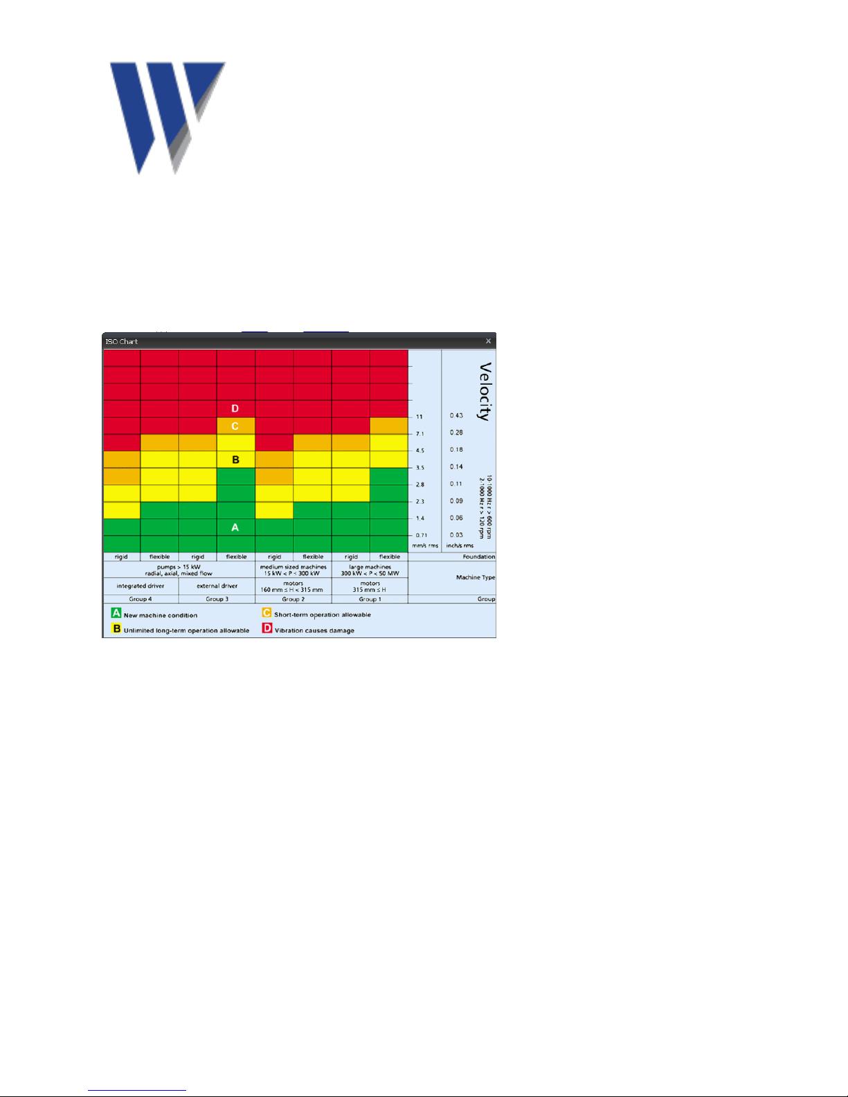
The ISO value background is color coded according to the ISO 10816-1 vibration velocity level chart,
according to the size and type of machine.
Bearing noise (BDU)
The bearing noise (high frequency vibration) in shown in Bearing Damage Units (BDU), where 100 BDU
corresponds to 1 g RMS (average) vibration measured above 1 kHz. BDU is a measure of the wear state of
the bearings in the equipment being monitored. The higher the number, the more worn the bearing.
1 g of high frequency vibration (100 BDU) corresponds to a high level of bearing noise and can be
considered indicative of a damaged bearing. Bearing noise can be considered roughly equivalent to
percentage of bearing wear.
Default alarm settings (can be changed in Advanced Settings menu
Red background above 100 BDU
Yellow background between 50 and 100 BDU
Green background below 50 BDU
Total acceleration (g)
This is the average RMS value of the total vibration acceleration measured by the meter over its entire
frequency range (2 Hz to 10 kHz). The reading is shown in units of g (Earth’s gravitational constant, 1 g =
9.81 m/s2).

91397 Rev B 09/17 Page 5 of 7
2.2.2 Vibration analysis
Press the SQUARE button again to display the readings of vibration velocity (mm/s or
inch/s) broken down into each of three bands.
The display shows the vibration level in frequency ranges based on multiples (1X, 2X and 3X) of the specified
machine run speed shown beneath the bars.
Note: In order to perform analysis it is important that the running speed of the machine is entered correctly.
This can be done with the Setup Wizard.
The frequency ranges of the VA bands are based on the following multiples of running speed:
1X = Unbalance
The level of vibration in the frequency band based on the running speed is usually indicative of how well
balanced the machine is. Large vibrations at the running speed indicate that the machine is out of balance.
Even a very well balanced machine will typically show some vibration at the running speed but the figure
should ideally be quite low (typically less than 2 mm/sec for a medium sized machine).
2X = Misalignment
A high level of vibration in the frequency band centered at twice the running speed is a possible indication of
misalignment. This is based on the fact that shaft misalignment can result in a double peak in the waveform
due to two different centers of gravity (one from each shaft). The accelerometer picks up a peak as each center
of gravity passes by, resulting in two positive and two negative peaks each revolution of the shaft. This typically
gives rise to a vibration signal at double the running speed of the machine.
3X = Looseness
High vibration in the frequency band centered at three times running speed indicates looseness (mounting
bolts, weak foundations, etc). It is not usual to see third order vibration in a machine unless there is structural
looseness that is being excited by the vibration of the machine.
2.2.3 Frequency spectrum
Press the SQUARE button again to display vibration levels as a frequency spectrum from
0 to 1 kHz.
The heights of the peaks indicate RMS vibration level (in/s or mm/s) at each frequency
point in the spectrum.
The readings to the right of show the frequency (Hz or RPM) and the RMS vibration level (in/s or mm/s) at the
position of the cursor (red dotted line). Move the cursor with the arrow buttons.
Press the arrow buttons to increase the resolution of the frequency axis from 100 (10 Hz or 600 RPM
resolution) to 800 lines (1.25 Hz or 75 RPM resolution). Increasing the resolution zooms into the frequency
spectrum. Scroll using the arrows to display the full spectrum at the higher resolution.
2.3 Settings menu

91397 Rev B 09/17 Page 6 of 7
The Settings menu can be accessed by pressing and holding down the SQUARE button for two seconds.
Navigate the menu with the arrow buttons. Press the SQUARE button to select a menu item.
2.3.1 Setup Wizard
Setup Wizard allows the machine running speed to be entered and the ISO alarm levels
to be set automatically according to the size and type of machine to be monitored.
The first screen shows the currently selected running speed in the pre-selected units (Hz
or RPM). Change the running speed with the arrow buttons.
Press the SQUARE button again to select machine type (motor or pump). If motor is
selected the size must be selected (under or over 300kW). If pump is selected, specify
whether it has an integrated or external drive unit.
Selecting the machine type and size allows the ISO alarm levels to be set accordingly, as
does specifying the type of mounting (rigid or flexible).
Unless a machine is bolted to a concrete floor, its mounting should be considered flexible.
Most motors and pumps are mounted on some kind of frame or structure and should be
considered flexibly mounted.
2.3.2 Load and Save readings
Press the SQUARE button to select Load & Save. Save Reading opens a screen which
allows the user to choose from one of three Memories in which to save the reading.
Selecting Load Reading lets the user load a previously saved reading for further review.
Demo Data loads two pre-stored demonstration vibraion data.
2.3.3 Advanced settings
Use the arrow buttons to scroll through the options, and the SQUARE button to select.
BDU settings
Change the alarm levels at which the BDU readings change color
Units
Sets velocity readings to be displayed in mm/s or inch/s.
Sets Run Speed to Hertz, RPM, or CPM.
2.3.3 Device settings
Use the arrow buttons to scroll through the options, and the SQUARE button to select.
Auto Off Time
Can be set from 1 to 60 minutes, in one minute increments
Brightness

91397 Rev B 09/17 Page 7 of 7
Can be set from 1 (least) to 100 full)
Language
Graph mode
Displays the frequency spectrum as either a bar or line graph.
3.0 Maintenance and care
Wipe the meter with a soft towel and lukewarm water. Do not place in dishwasher or other cleaning device or
use detergents to clean housing. Do not subject meter to water at or above 122°F (50°C). Care must be taken
when the batteries are changed.
Do not drop the instrument. Damage to the probe tip/accelerometer and/or OLED display may occur.
No internal user serviceable parts
4.0 Accessories and options
Standard accessories
Carrying case with foam insert
Standard stinger
Extended length stinger
Protective magnetic boot
5.0 Technical assistance
5.1 Technical assistance
For technical assistance, please contact Wilcoxon Sensing Technologies at 301-330-8811or email
5.2 Customer service
For customer service, please contact Wilcoxon Sensing Technologies at 301-330-8811, or email
Table of contents
Other Wilcoxon Measuring Instrument manuals


Popular Measuring Instrument manuals by other brands

ABB
ABB EasyLine EL3000 Operating instruction

Gossen MetraWatt
Gossen MetraWatt MAVOSPEC BASE operating instructions

RigExpert
RigExpert ZOOM series Software manual

P3 International
P3 International Kill A Watt user manual

FoamPRO
FoamPRO MultiFlo Installation and operation manual

Sokkia
Sokkia CX-62 Operator's manual


