Wilcoxon PROFESS GV2510 User manual


2 | 15
Operation Manual –GV2510
2/2023, Rev 1.1
Machine Monitoring Systems
PROFESS spol. s r.o.
Květná 5, 326 00 Plzeň,
Czech Republic
Caution: This guide should be read carefully before operating the unit.
Safety section
ReferenceMate handheld shakers can be used safely when the instructions in this manual
are carefully followed. This section summarizes the safety considerations. Reminders in the
form shown below will appear in the detailed instructions to assure operator awareness of
these safety considerations. Qualified personnel should use the GV2510 only after
becoming thoroughly familiar with this manual.
WARNING: This symbol is used in the instruction manual when the safety of the
operator must be considered. The instruction manual should be consulted and
read carefully.
CAUTION: This symbol is used when caution is needed to prevent damage to
equipment. It is used where careful attention to certain procedures described in
the instruction manual is needed. This symbol is also used to emphasize
procedures other than normal operating procedures.
Safety summary
1. The products covered in this installation guide do not require any special
precautions, protective devices, or equipment.
2. Because these products are designed to be used in an industrial environment,
personnel involved with the operation of this instrument should be familiar with all
plant safety requirements before beginning use.
3. The ReferenceMate is NOT certified for use in explosive or hazardous environments.
4. There are no user-serviceable parts within this product.
5. Use common sense and avoid haste during operation.

3 | 15
Operation Manual –GV2510
2/2023, Rev 1.1
Machine Monitoring Systems
PROFESS spol. s r.o.
Květná 5, 326 00 Plzeň,
Czech Republic
Contents
1.0 Introduction.......................................................................................4
2.0 Description........................................................................................4
3.0 Applicable models ............................................................................4
4.0 Set-up.................................................................................................5
5.0 Operation...........................................................................................6
5.1 Operating steps ..................................................................................................6
5.2 Operational details..............................................................................................7
5.2.1 Mounting....................................................................................................................9
5.2.2 Power ON/OFF..........................................................................................................9
5.2.3 Frequency selection.................................................................................................10
5.2.4 RMS/PEAK..............................................................................................................10
5.2.5 BAT (low power) LED............................................................................................... 10
5.2.6 OOR LED ................................................................................................................11
5.2.7 Orientation during operation.....................................................................................11
6.0 Testing triaxial
transducers
.............................................................12
6.1 Universal AC adaptor........................................................................................12
7.0 Reference test
points
......................................................................13
7.1 Background information....................................................................................13
7.2 Recommended instrumentation set-up.............................................................14
7.3 Protection from the environment.......................................................................15
8.0 Storage ............................................................................................15
9.0 Technical assistance and customer service .................................15

4 | 15
Operation Manual –GV2510
2/2023, Rev 1.1
Machine Monitoring Systems
PROFESS spol. s r.o.
Květná 5, 326 00 Plzeň,
Czech Republic
1.0 Introduction
This guide is designed to assist the user in the proper operation of the ReferenceMate
portable reference source (handheld shaker). Further information is provided on the use of
accessory items.
2.0 Description
The ReferenceMate portable vibration reference source enables users in the field to easily
verify sensor performance and the integrity of the cabling between the sensor and read-out
equipment, either online or portable units.
A built-in reference accelerometer assures that a 1 g test level is maintained for a unit under
test (sensor and mounting hardware) weighing up to 250 grams.
Frequency of operation and measurement types (peak/RMS) are
selected with front panel push buttons.
•61.4 Hz for imperial measurements, where 1 g is equal to 1 inch
per second (ips), ideal for use with velocity sensors
•100 Hz to confirm accelerometer performance at the same
reference frequency used by most manufacturers
•159.2 for metric measurements, where 1 g is equal to 9.81
m/sec2and 9.81 mm/sec.
A bottom-mounted D-ring belt clip is included for hands-free transport between locations
when in the field. The belt clip can be removed and replaced with a 70 lbf pull force magnet
(optional) for attachment to metal structures for hands-free operation.
LEDs notify the user when the battery condition falls below operational levels or if the unit
is overloaded. Reference test points are provided to test and check calibration of the
shaker’s internal accelerometer.
3.0 Applicable models
The manual covers the model GV2510 handheld shaker included in the REF2510 and
REF2510R kits, and the use of applicable accessories, both standard and optional.
5 | 15
Operation Manual –GV2510
2/2023, Rev 1.1
Machine Monitoring Systems
PROFESS spol. s r.o.
Květná 5, 326 00 Plzeň,
Czech Republic
4.0
Set-
up
The unit is powered by four AA alkaline batteries (provided with the unit). Rechargeable and
lithium batteries may also be used.
NOTE: Never mix battery types. For proper operation, use all alkaline, NiCad,
etc. types. When replacing batteries, always replace all four cells.
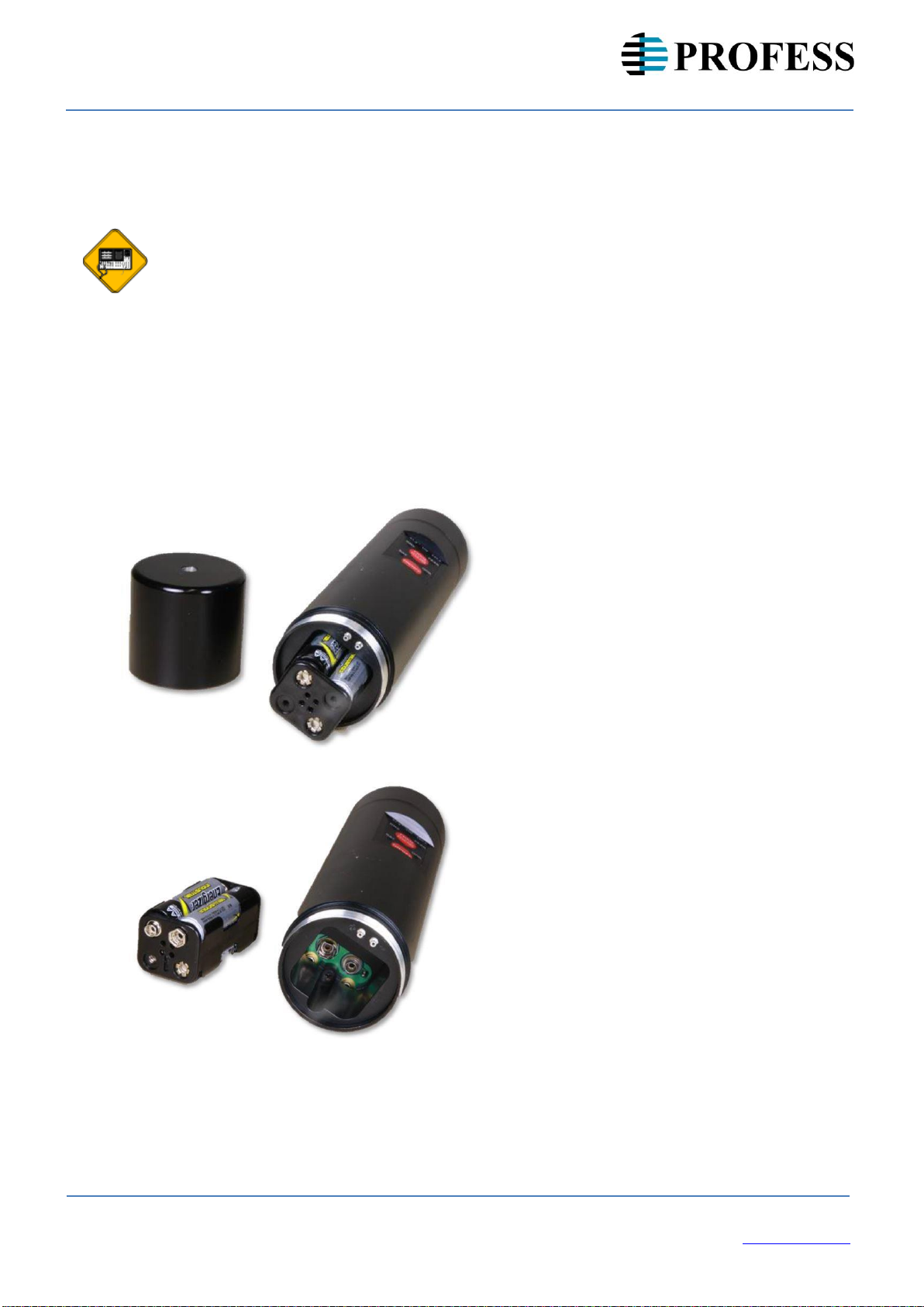
Access the battery compartment by unscrewing and removing the bottom cap (see figure
1A). Remove the battery holder and insert four AA batteries into the holder, being careful to
observe correct polarity (see figure 1B). After the batteries are installed, insert the holder
into the battery cup and gently snap the holder onto the contacts. Re-attach the bottom
cap. The ReferenceMate is now ready to operate.
The shaker does not contain a battery charging system. If rechargeable batteries are used,
they must be charged external to the shaker.
Figure 1A: ReferenceMate with bottom cap
removed showing battery holder
Figure 1B: ReferenceMate with battery holder
removed from battery compartment

6 | 15
Operation Manual –GV2510
2/2023, Rev 1.1
Machine Monitoring Systems
PROFESS spol. s r.o.
Květná 5, 326 00 Plzeň,
Czech Republic
5.0
Operation
Below are numbered steps to follow for operating the GV2510. Each step is described in
detail in section 5.2.
WARNING: The GV2510 is NOT certified for use in hazardous environments.
5.1
Operating steps
Please refer to Figure 2 for details.
1. The ReferenceMate is provided with a mounting head that accepts a 1/4-28 mounting
stud. Attach the unit to be tested (UUT- accelerometer, piezovelocity sensor, etc.) to the
ReferenceMate mounting platform, making certain to only hand-tighten the
accelerometer to no more than 10 in-lb (112 N-cm). If the accelerometer has something
other than a 1/4-28 mounting thread, use the appropriate adaptor outlined in Table 2.
The appropriate mounting torques for adaptors used with the GV2510 are also shown in
Table 2. An open end wrench is provided to stabilize the shaker head and make certain
the mounting platform (shaker head) is not excessively torqued. Over torqueing the
shaker head can result in permanent damage to the shaker suspension system. To
stabilize the shaker head during accelerometer attachment, slip the open end of the
wrench over the flats provided on the shaker head.
2. Once the UUT (and any mounting accessory) is mounted to the ReferenceMate head,
connect all cables from the UUT to the readout equipment. You are now ready to test
your device.
3. Press the ON/OFF button to initiate the 1 g test cycle. The OOR indicator (out of
range indicator) will come on momentarily as the control circuit stabilizes to a 1 g test
level. The shaker will shut off after approximately 90 seconds.
a.
Allow at least three seconds for the GV2510 to achieve the controlled vibration level.
Observe the BAT and OOR LEDs and make sure they are not illuminated. If the BAT
indicator remains on, or if the unit will not stay on after releasing the ON/OFF switch, replace
the batteries and try again. If the OOR LED illuminates, the maximum load has been
exceeded. The excessive weight must be removed, otherwise a 1 g test level will not be
achieved.
b.
To defeat the auto shutoff feature and enable continuous operation, press and hold the
FREQ button while turning the unit on. After the unit turns on, all three frequency LEDs will
briefly illuminate to indicate the shaker is in CONTINUOUS operating mode. The
ReferenceMate will now continue to operate until the ON/OFF button is depressed again.
This feature may be useful when the ReferenceMate is connected to an AC supply, such as
in a laboratory environment. See Section 6.1.
When the unit is turned off, it will revert to the AUTO-OFF mode.
7 | 15
Operation Manual –GV2510
2/2023, Rev 1.1
Machine Monitoring Systems
PROFESS spol. s r.o.
Květná 5, 326 00 Plzeň,
Czech Republic
4. Once the GV2510 has been turned on and stabilized, a frequency LED and
measurement type LED will illuminate. They will indicate the choices made when the
shaker was last turned off. To change the frequency (61.4, 100.0 or 159.2 Hz), press
and release the FREQ button. The frequency LED will toggle through the above three
choices each time the FREQ button is pressed. To change the measurement type,
press and hold the FREQ button for approximately 5 seconds. The measurement type
will toggle between RMS and Peak each time the FREQ button is pressed and held this
way.
5. To turn the ReferenceMate off before the end of its autoshutdown cycle, press the ON/OFF
button.
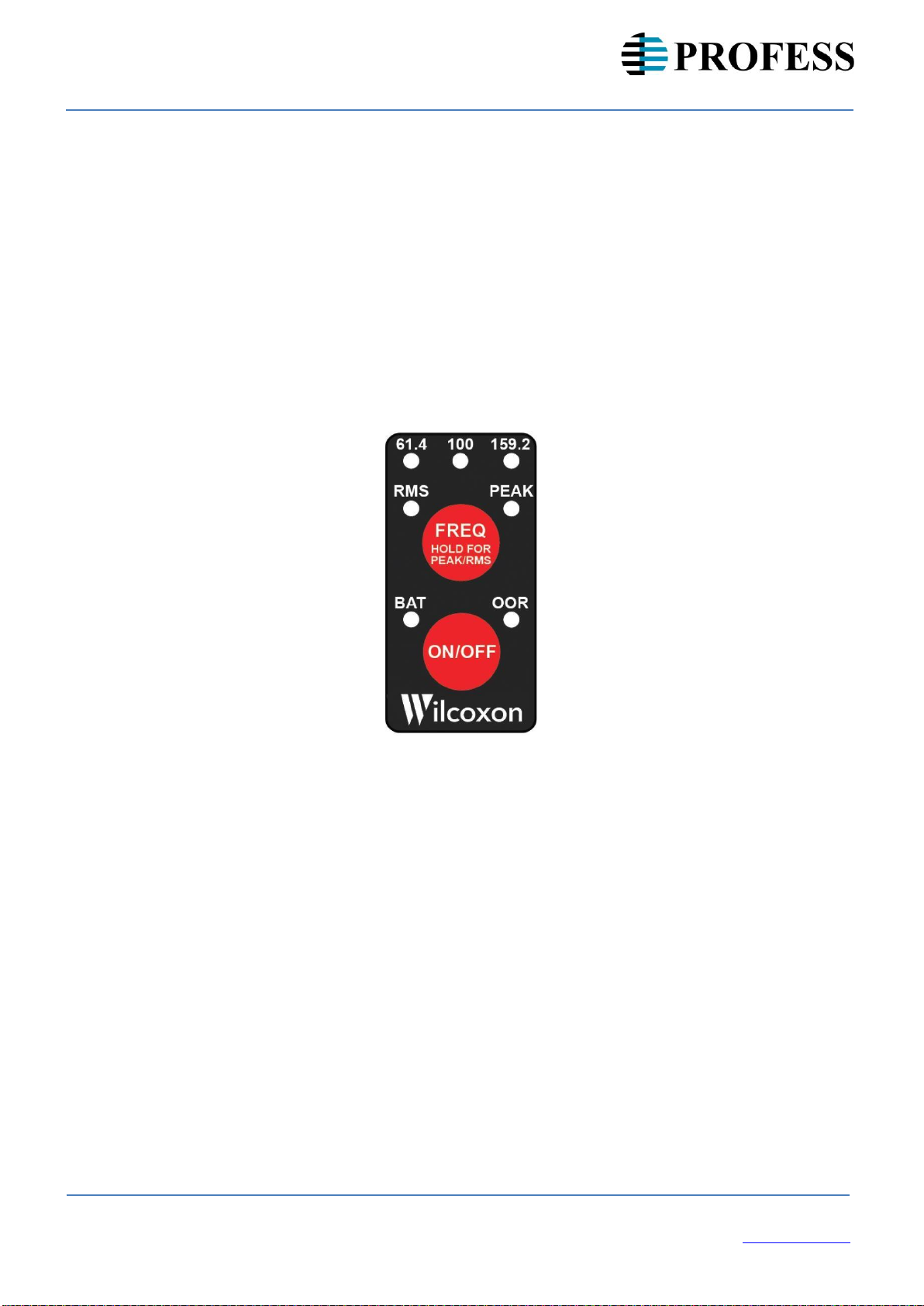
Frequency indicators
61.4, 100.0, 159.2 Hz
Frequency selection
Press the FREQ button to select
the desired frequency
Lowbattery indicator
Illuminates when battery
voltage is low and batteries
need to be replaced
Peak/RMS mode indicators
Indicate peak or RMS output
Peak/RMS mode selection
Hold down the FREQ button to choose
between peak and RMS output
Out-of-range indicator
Illuminates if the unit cannot maintain 1 g
acceleration due to overloading
Power
Press the ON/OFF button to turn the unit
on and off. The unit will power off after
90 seconds. To disable the auto-off
feature, hold down the FREQ button while
turning the unit on.
Figure 2: Control panel of the ReferenceMate
5.2
Operational details
Once the UUT has been mounted on the ReferenceMate and a 1 g test level has been
achieved, you can check the output of your sensor.
Table 1 shows the relationship between acceleration, velocity and displacement at the three
test frequencies. If taking imperial measurements (US) use Table 1a and select 61.4 Hz as
your frequency. 1 g (acceleration) at 61.4 Hz is equivalent to 1 in/sec (velocity). If Peak
measurement type is selected, both acceleration and velocity will be peak levels.
Conversely, if RMS is the measurement type, then both values will be in RMS.

8 | 15
Operation Manual –GV2510
2/2023, Rev 1.1
Machine Monitoring Systems
PROFESS spol. s r.o.
Květná 5, 326 00 Plzeň,
Czech Republic
The equivalent peak to peak displacement values in mils are shown in Table 1a for
reference. For those using the metric system, Table 1b shows the equivalent values. All the
values below are represented in Graph 1.
Table 1a: English (1 g) Table 1b: Metric (1 g = 9.81 m/s2)
Graph 1: The relationships between 61.4 Hz, 100 Hz, and 159.2 Hz
Constantdisplacement,
µm Constant velocity,
mm/s Constant velocity,
ips Constant
acceleration, 1 g
61.4 Hz for imperial measurements 100 Hz to verify standard 159.2 Hz for metric measurements
1 g (acceleration) and 1 ips (velocity) calibration sheet values 9.81 m/sec2(acceleration) and 9.81 mm/sec (velocity)
Frequency
Velocity
Displacement
Hz
CPM
in/sec
mils, peak-peak
Peak mode
RMS mode
61.4
3684
1.00
5.18
7.34
100.0
6000
0.61
1.96
2.76
159.2
9552
0.39
0.77
1.09
Frequency
Velocity
Displacement
Hz
CPM
mm/sec
µm, rms
Peak mode
RMS mode
61.4
3684
25.41
5.18
7.34
100.0
6000
15.61
1.96
2.76
159.2
9552
9.81
0.77
1.09

9 | 15
Operation Manual –GV2510
2/2023, Rev 1.1
Machine Monitoring Systems
PROFESS spol. s r.o.
Květná 5, 326 00 Plzeň,
Czech Republic
5.2.1 Mounting
The UUT can be attached directly to the shaker head using a 1/4-28 stud. Adaptor studs and
plates are available for mounting sensors with different size mounting threads. See Table 2
below.
NOTE: The stud or adaptor plate should be mounted
finger tight only, not exceeding 10 in-lb (112 N-cm) into
the shaker head. Exceeding the maximum torque may
damage the shaker. It is recommended to use the open
end wrench when mounting sensors to stabilize the
shaker armature.
Table 2: Recommended torque values for standard and optional accessories
Standard mounting accessory for REF2510 and REF2510R kits
Part
number
Description
Rec.
torque
REF2510
REF2510R
in-lb
N-
m
SF6
1/4-28
to
1/4-28
mounting
stud
24
2.7
Optional mounting accessories
Part
number
Description
Rec.
torque
REF001
REF002
in-lb
N-
m
SF3
1/4-28
to
10-32
adaptor stud
24
(18)
2.7
(2.0)
13249-
01
1/4-28 to 8-32 adaptor plate (997 and 712 sensors)
24
(20)
2.7
(2.3)
13249-
02
1/4-28 to 10-32 adaptor plate
24
(18)
2.7
(2.0)
13267-
01
90°
adaptor
plate
(993
series
sensors)
24
(24)
2.7
(2.7)
SF6M-
1
1/4-28 to M6 adaptor stud
24
(30)
2.7
(3.4)
SF6M
1/4-28 to M8 adaptor stud
24
(40)
2.7
(4.5)
13249-
03
1/4-28 to M4 adaptor plate (997 and 712 sensors)
24
(20)
2.7
(2.3)
13249-
04
1/4-28 to M6 adaptor plate (captive screw sensors)
24
(30)
2.7
(3.4)
13249-
05
1/4-28 to M8 adaptor plate (captive screw sensors)
24
(40)
2.7
(4.5)
A specially designed angular plate is available for calibrating the 993B-7-M12 triaxial
accelerometer. This plate will excite all three axes simultaneously, resulting in 0.57 g per
axis. See section 6.0.
5.2.2 Power ON/OFF
Turns on the shaker for approximately 90 seconds. The unit will default to the previously
selected options. To defeat the auto shutoff feature and enable continuous operation, hold
down the FREQ button while turning the unit on. All three frequency LEDs will briefly
illuminate to indicate the shaker is in CONTINUOUS operating mode. The unit will now
operate until the ON/OFF button is pressed again. When the unit is turned off, it will revert
to the AUTO-OFF mode.
10 | 15
Operation Manual –GV2510
2/2023, Rev 1.1
Machine Monitoring Systems
PROFESS spol. s r.o.
Květná 5, 326 00 Plzeň,
Czech Republic
5.2.3 Frequency selection
The user has a choice of three frequencies. Momentarily press the FREQ button to select
the desired frequency as indicated on the respective LED. During frequency changes, the
output of the shaker is turned off momentarily. It is normal for the OOR indicator to
illuminate briefly after a new frequency is selected. See table 1 for additional information.
The ReferenceMate 2500 will always produce an amplitude of 1 g at the selected frequency.
•61.4 Hz is the most common frequency selected for machinery vibration and
analysis when working with imperial units (US). One g at 61.4 Hz is equal to 1
in/sec (ips) velocity.
•100 Hz is the preferred frequency for checking accelerometer performance against
calibration data. 100 Hz is the most common reference frequency used by
accelerometer manufacturers, thus allowing for a comparison with the original
calibration certificate.
•159.2 Hz is the most common frequency used when working in metric units where 1
g is equal to 9.81 m/sec2 acceleration, 9.81 mm/sec velocity and 9.8 μm
displacement.
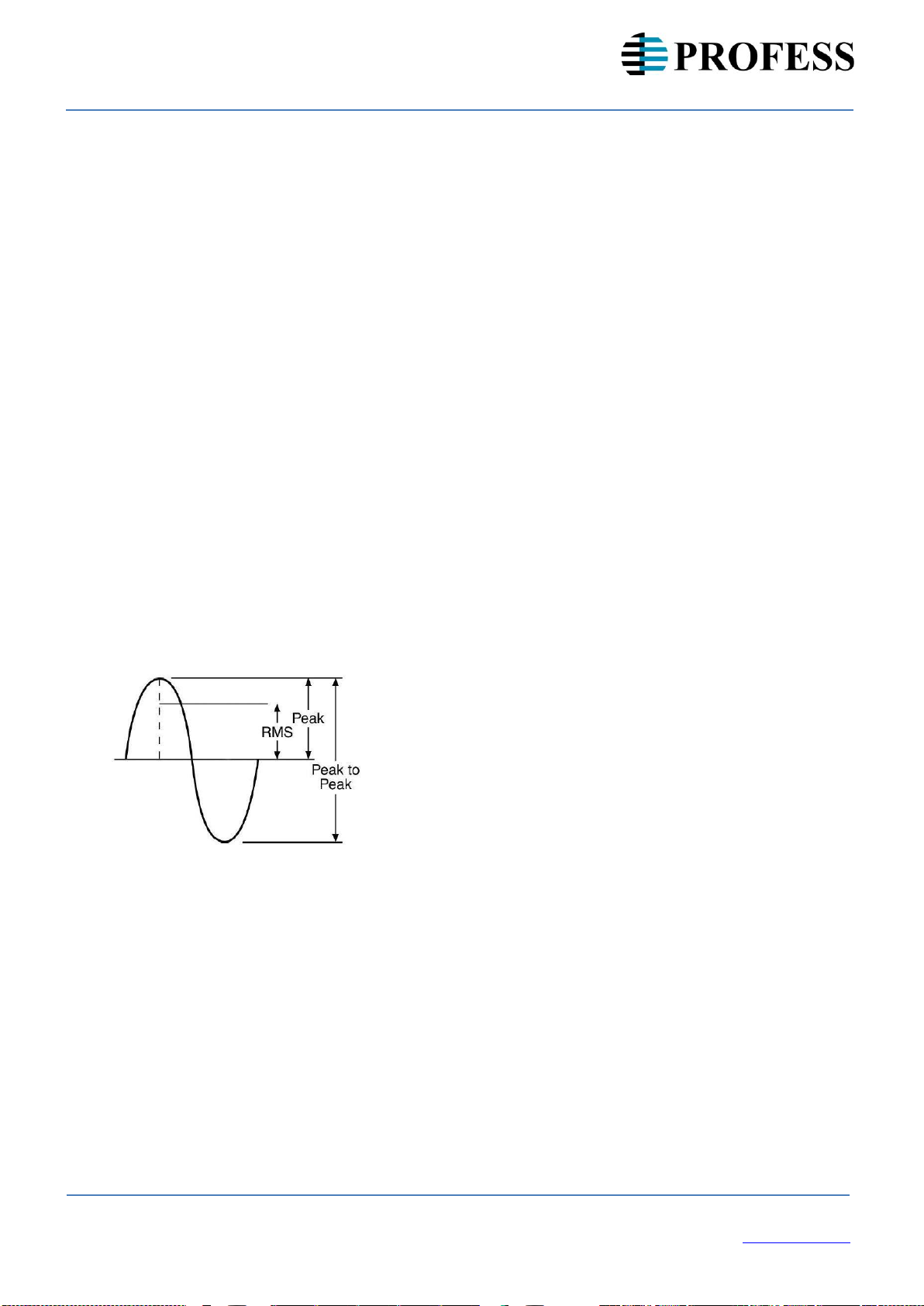
5.2.4 RMS/PEAK
Select between RMS and PEAK by holding down the FREQ button. Figure 3 below
illustrates the relationship between PEAK and RMS.
RMS value = 0.707 x peak value
Peak value = 1.414 x RMS value
Peak to peak value = 2 x peak
value
Peak to peak value = 2.828 x RMS value
Figure 3: the relationship between peak, RMS, and peak-to-peak
5.2.5 BAT (low power) LED
The red BAT LED indicates remaining battery life is short and the batteries should be
replaced soon. (See section 4 for battery installation instructions). If the battery voltage
becomes too low, the unit will shut off and will not operate. The internal power supply is well
regulated and 1g acceleration will be maintained even though the battery voltage fluctuates.
Battery life is dependent on the type of batteries used, weight of the load and if the shaker is
being operated in the Peak or RMS mode. Table 3 shows approximate battery life
expectancy

11 | 15
Operation Manual –GV2510
2/2023, Rev 1.1
Machine Monitoring Systems
PROFESS spol. s r.o.
Květná 5, 326 00 Plzeň,
Czech Republic
under various payloads and is based on operating the shaker in RMS mode. Operation in
Peak mode will result in longer run times.
Table 3: Battery life expectancy in continuous mode
Alkaline
EnergizerEN91
1500-1800
mAh
NiMHrechargeable
Energizer
NH15-2300
2300 mAh
Lithium
EnergizerL91
3000mAh
Payload
(grams)
Hours
90 sec
cycles
Hours
90 sec
cycles
Hours
90 sec
cycles
61.4
Hz
16
12
480
13
501
18
720
90
20
800
49
767
36
1440
254
32
1280
29
1160
42
1680
100.0
Hz
16
32
1280
29
1175
45
1800
90
31
1250
24
968
45
1800
254
8
320
10
400
15
600
159.2
Hz
16
32
1280
29
1143
43
1720
90
24
960
21
836
40
1600
254
6
240
8
305
12
480
5.2.6 OOR LED
The control time is the required for the unit to achieve the controlled vibration level. The red
OOR LED will be illuminated during the control time cycle. Once the LED goes out, the unit
is ready for operation. This is normally less than 3 seconds.
5.2.7 Orientation during operation
The ReferenceMate may be held in any position during operation without worry of causing
an error in the reading. If the control circuitry is unable to maintain 1g test level, the red
OOR LED will illuminate. Low battery power or a total load exceeding 250 grams can also
cause this condition. When considering the total payload on the shaker, attention must also
be given to weights of the sensor, mounting method (stud or adaptor) and the cable and
connector.
12 | 15
Operation Manual –GV2510
2/2023, Rev 1.1
Machine Monitoring Systems
PROFESS spol. s r.o.
Květná 5, 326 00 Plzeň,
Czech Republic
6.0
Testing triaxial transducers
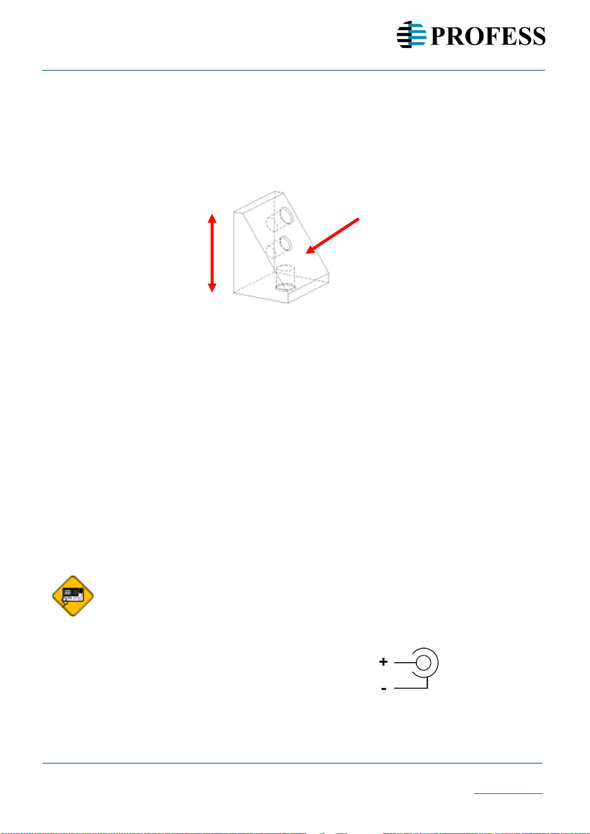
An optional triaxial accelerometer angled adaptor can be purchased separately (part
number TAA01). The fixture has a mounting surface that has been designed to excite all of
the sensor’s axes simultaneously. The resulting vibration level will be approximately 57.8%
of the applied acceleration. It is important that the sensor be mounted using its positioning
pin to achieve the desired result.
Sensor mounting surface
Sensitive axis
Figure 4: Triaxial mounting adaptor that allows for simultaneous excitation of all three axes
Note that there are two holes on the mounting surface. The 10-32 threaded hole is for
mounting the sensor, the unthreaded hole is to accommodate the alignment pin provided on
the 993B-7- M12 accelerometer. The weight of the fixture is 93 grams.
6.1
Universal AC adaptor
If AC operation of the ReferenceMate2500 is required, part number REF003 is available.
This AC adaptor comes with several universal plug adaptors and will operate from 50/60 Hz
110/220 VAC.
To power the shaker with the AC adaptor, unscrew and remove the DC jack cover on the
rear of the unit. Store the jack cover in a safe location. Connect the coaxial power plug of
the power supply to the DC jack on the ReferenceMate. When the power plug is inserted
into the DC jack, the batteries are automatically disconnected. After connecting the adaptor
to the shaker, plug the adaptor into an AC supply.
CAUTION: The external supply is rated for indoor use only. The shaker should
not be powered with an external supply when used outdoors or in wet
locations. The shaker does not meet the IP54 rating when the DC jack cover is
not securely installed. The DC jack cover should always be installed whenever
an external supply is not being used.
Voltage: 6 VDC
Current: 800 mA
Plug: 2.1 mm, center conductor positive

13 | 15
Operation Manual –GV2510
2/2023, Rev 1.1
Machine Monitoring Systems
PROFESS spol. s r.o.
Květná 5, 326 00 Plzeň,
Czech Republic
7.0
Reference test points
Test points located in the battery compartment allow access to the control voltage used as
part of the motor feedback loop. Using an accurate AC DMM and/or an oscilloscope can
help make a determination as to the condition of the unit.
To access the reference test points, remove the battery cover (see section 4) and find the
two turret style connectors and connect the desired test leads. The “+” terminal is the AC
output voltage. The “-“ terminal is system ground.
CAUTION: When accessing the test points, proper precautions should be taken
against ESD (electrostatic discharge). Checking the test point voltage should be
done only in an ESD-safe environment.
Test points
Figure 5: Test points
7.1
Background information
The GV2510 contains an internal sine wave generator with a reference accelerometer in
the control loop to maintain a continuous output level of 1 g in either peak or RMS. The
reference accelerometer’s signal is fed through a charge amplifier to the control
electronics.
Proper operation of the feedback control loop and accuracy of the internal voltage reference
can be verified by monitoring the voltage at the test point output. Since we are observing
the accelerometer signal, the test points will also provide information as to any mechanical
or significant electrical anomalies. In the event the GV2510 is dropped or otherwise abused,
measuring the output from the test points will confirm if the unit is still operational.

14 | 15
Operation Manual –GV2510
2/2023, Rev 1.1
Machine Monitoring Systems
PROFESS spol. s r.o.
Květná 5, 326 00 Plzeň,
Czech Republic
7.2
Recommended
instrumentation
set-up
A digital multimeter (DMM) can be used to measure the
signal amplitude. The DMM should be a high quality unit that
has a current calibration certificate to ensure measurement
accuracy. Figure 6 shows the attachment of a probe and clip
lead going to a DMM.
An oscilloscope will provide information as to the shaker’s
wave shape. The test point output should be a sine wave
with low distortion (less than 7%), as shown in Figure
7a. Excessive distortion or high levels of noise (Figure 7b) Figure 6: Probe connected to the test point pins
indicates possible mechanical damage to the shaker mechanism. If high levels of distortion, an
incorrect output level, or out-of-tolerance frequency is observed, the GV2510 should be returned to
the factory for service. There are no user-serviceable parts in the unit.
Figure 7a: Acceptable sine wave from ReferenceMate Figure 7b: Example of unacceptable noise
The table below shows the expected test point output voltage amplitudes. The amplitude
depends on the peak/RMS setting, as shown. Measured values should be within ±3.0% of
those specified.
Table 4: Test output voltages
Setting
RMS
value
Peak
value
Peak to Peak value
RMS
100
mV
141
mV
282
mV
Peak
70.7
mV
100
mV
200
mV
A frequency counter may also be used to confirm the frequency of the excitation signal. The
frequency should be within ±1.5% of the selected frequency.

15 | 15
Operation Manual –GV2510
2/2023, Rev 1.1
Machine Monitoring Systems
PROFESS spol. s r.o.
Květná 5, 326 00 Plzeň,
Czech Republic
7.3
Protection from the environment
The ReferenceMate meets Ingress Protection Rating IP54 for dust and water resistance.
The unit is O-ring sealed to be resistant to dirt, dust and moisture encountered during
normal operation. Although moisture resistant, the unit is NOT submersible.
CAUTION: To meet the IP54 rating, both the battery cap and DC power jack
cover must be securely installed on the unit. Do not expose the unit to dust or
moisture without both of these protective mechanisms in place.
8.0 Storage
If the unit is going to be out of service for an extended period of time, store in a dry
controlled environment. Remove the batteries to prevent possible damage caused by the
leakage of battery fluids. Storage temperature range is -40°C (-40°F) to 85°C (185°F).
9.0 Technical assistance and customer service
For technical assistance and all customer service inquiries, please contact
info@wilcoxon.com or by phone at +1 (301) 330-8811.
Table of contents
Other Wilcoxon Measuring Instrument manuals


