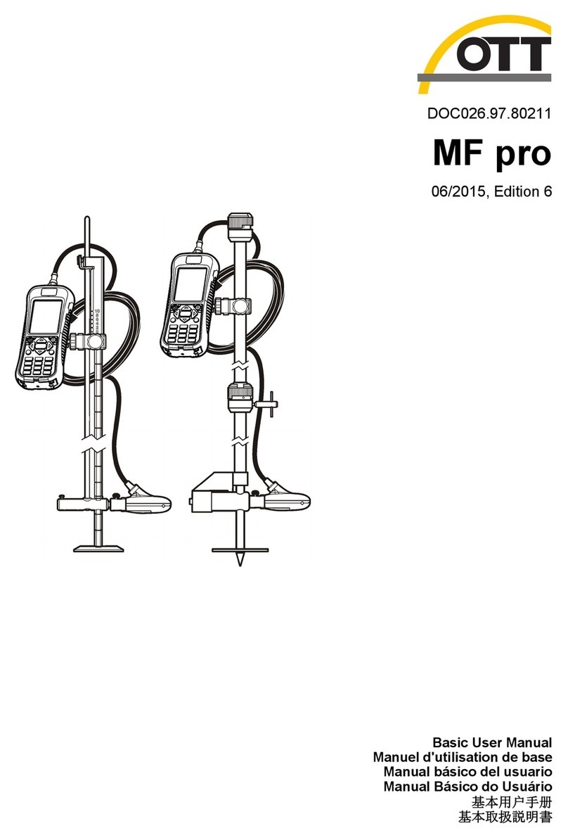
OTT ADC User manual

DOC026.53.80104
OTT Acoustic Digital Current
(ADC) Meter
05/2013, Edition 3 (North American Version) 10.500.001.B.U.
User Manual


Table of Contents
Specifications..............................................................................................................3
General information..................................................................................................4
Safety information........................................................................................................4
Use of hazard information............................................................................................ 4
Precautionary labels....................................................................................................5
Certification..................................................................................................................5
Product overview.......................................................................................................6
System components....................................................................................................6
About the sensor..................................................................................................8
Temperature compensation.................................................................................. 8
Installation.....................................................................................................................8
About the power supply and battery............................................................................8
Battery specifications ........................................................................................... 9
Charge the battery................................................................................................9
Connect the sensor cable to the handheld unit...........................................................9
To disconnect the sensor...................................................................................10
Attach the handheld display unit to the wading rod...................................................10
Attach the sensor to a wading rod.............................................................................12
Operation.....................................................................................................................12
Turn the handheld unit On and Off............................................................................12
Display screen...........................................................................................................13
Operating key icons ..................................................................................................13
Menu navigation and data entry................................................................................14
Display symbols ........................................................................................................14
Main Menu ................................................................................................................15
System settings.........................................................................................................15
Advanced settings ....................................................................................................16
Upgrade firmware......................................................................................................17
Performing measurements..................................................................................18
Station set up.............................................................................................................18
Angle of flow.......................................................................................................19
Quality control............................................................................................................19
Adjust quality thresholds..................................................................................... 20
Quick quality checks..................................................................................................21
Internal quality check.................................................................................................22
Calibrate the pressure cell (depth calibration)...........................................................22
Turn the depth sensor on or off..........................................................................23
About sensor offsets..................................................................................................23
Perform a single point measurement.........................................................................24
Velocity and discharge measurement methods.........................................................24
Methods for velocity measurement..................................................................... 24
Methods of discharge calculation.......................................................................26
Measurement settings menus.................................................................................... 28
Measurement settings [1/3] ...............................................................................28
Measurement settings [2/3]................................................................................28
1

Measurement settings [3/3]................................................................................29
Field quality checks...................................................................................................30
Perform a discharge measurement...........................................................................30
Perform an ICE measurement...................................................................................33
Discharge measurement window .............................................................................. 34
QReview discharge measurement summary file.......................................................35
Delete a file................................................................................................................36
QReview software....................................................................................................36
Overview....................................................................................................................36
QReview main menu options ............................................................................. 37
Installation..................................................................................................................37
Install the QReview software..............................................................................37
Operation...................................................................................................................37
Change the language.........................................................................................37
Change the units................................................................................................38
Connect the ADC................................................................................................ 38
Retrieve ADC data.............................................................................................. 39
Open and view ADC data files............................................................................ 40
Export data.........................................................................................................43
Edit screen.......................................................................................................... 43
Print a report.......................................................................................................44
Maintenance...............................................................................................................44
Handheld unit maintenance.......................................................................................45
Sensor maintenance..................................................................................................45
Troubleshooting.......................................................................................................45
Measurement guidance.............................................................................................45
Common problems....................................................................................................45
Device warning messages ........................................................................................46
Measurement warnings and errors ...........................................................................47
View system status....................................................................................................48
Contact information................................................................................................48
Table of Contents
2

Specifications
Specifications are subject to change without notice.
Specification Details
Velocity measurement (Acoustic
Ultrasonic Transducers)
Measurement range: – 0.2 m/s to 2.4 m/s (–0.65 ft/s to 7.87 ft/s)
Accuracy: ±1% of the measured value, ±0.25 cm/s (±0.01 ft/s)
Resolution: 0.001 m/s (0.001 ft/s)
Ultrasonic transducers
Frequency: 6 MHz
Beam angle: 20°
Measured volumes
Distance from the sensor: 10 cm (3.93 in.)
Diameter: 1 cm (0.39 in.) per sound pulse
Length: 5 cm (1.97 in.)
Depth measurement (Piezoresistive
pressure cell (absolute))
Measurement range: 0 to 5 m (0 to 16.4 ft)
Accuracy: 0.1% FS
Resolution: 0.01% FS
Maximum overload: 1.5 times the measuring range
Temperature measurement
Measuring range: –5 to 40°C (23 to 104 °F)
Accuracy: ± 0.5 °C
Resolution: 0.1 °C (0.1 °F)
Salinity Range: 0 to 50 ppt (mg/L)
Power supply
Type of batteries: Rechargeable NiMH, fixed battery pack
Life duration: > 14 hours (the battery lifetime is affected by
environmental conditions and charging cycles)
Charging cycles: > 500 (charging cycles vary by use, environment and
other factors)
Nominal voltage: 9.6 VDC
External class II AC/DC power supply: Input 90–240V, 50/60 Hz
Output voltage of power supply: 18 VDC/VAC
Operating conditions
Operating temperature range: –20 to 60 °C (–4 to 140 °F)
Storage temperature range: –40 to 85 °C (–40 to 185 °F)
Shock resistance: compatible with EN 60068-2-32
Dimensions and weight
Cylindrical sensor body: Ø 40 mm (0.20 in.)
Length: 14.5 cm (5.71 in.)
Weight in air: 800 g (1.76 Ib)
Weight in water: 620 g (1.37 Ib)
Handheld unit:
Dimensions: 23.3 x 8.3 x 3.2 cm (9.20 x 11.41 x 1.26 in.)
Weight: 700 g (1.76 Ib)
English 3

Specification Details
Material
Sensor housing: Delrin®/stainless steel
Screws: stainless steel
Handheld unit: aluminium, powder coated
Keypad: Autotex V 150 XI
IP protection class Handheld unit: IP65 (housing, keypad)
Sensor: IP68
EMC
EN 61000-6-2
EN 61000-6-4
FCC Part 15
EMC Directive 2004/108/EU, Article 5
Internal data memory Capacity: 4 MB (flash)
OTT QReview software
Operating system: Windows®98, Windows®ME, Windows®NT,
Windows®2000, Windows®XP, Windows® Vista, Windows® 7
Functionality: Data transfer from handheld unit, Data check and
processing, Data export (XML, ASCII)
General information
Revised editions are found on the manufacturer’s website.
Safety information
N O T I C E
The manufacturer is not responsible for any damages due to misapplication or misuse of this product including,
without limitation, direct, incidental and consequential damages, and disclaims such damages to the full extent
permitted under applicable law. The user is solely responsible to identify critical application risks and install
appropriate mechanisms to protect processes during a possible equipment malfunction.
Please read this entire manual before unpacking, setting up or operating this equipment. Pay
attention to all danger and caution statements. Failure to do so could result in serious injury to the
operator or damage to the equipment.
Make sure that the protection provided by this equipment is not impaired. Do not use or install this
equipment in any manner other than that specified in this manual.
Use of hazard information
D A N G E R
Indicates a potentially or imminently hazardous situation which, if not avoided, will result in death or serious injury.
WARNING
Indicates a potentially or imminently hazardous situation which, if not avoided, could result in death or serious
injury.
CAUTION
Indicates a potentially hazardous situation that may result in minor or moderate injury.
N O T I C E
Indicates a situation which, if not avoided, may cause damage to the instrument. Information that requires special
emphasis.
4 English

Precautionary labels
Read all labels and tags attached to the instrument. Personal injury or damage to the instrument
could occur if not observed. A symbol on the instrument is referenced in the manual with a
precautionary statement.
This symbol, if noted on the instrument, references the instruction manual for operation and/or
safety information.
This symbol indicates that a risk of explosion is present.
This symbol indicates that a risk of fire is present.
This symbol indicates the need for protective eye wear.
Electrical equipment marked with this symbol may not be disposed of in European public disposal
systems after 12 August of 2005. In conformity with European local and national regulations (EU
Directive 2002/96/EC), European electrical equipment users must now return old or end-of-life
equipment to the Producer for disposal at no charge to the user.
Note: For return for recycling, please contact the equipment producer or supplier for instructions on how to return
end-of-life equipment, producer-supplied electrical accessories, and all auxiliary items for proper disposal.
Certification
Canadian Radio Interference-Causing Equipment Regulation, IECS-003, Class A:
Supporting test records reside with the manufacturer.
This Class A digital apparatus meets all requirements of the Canadian Interference-Causing
Equipment Regulations.
Cet appareil numérique de classe A répond à toutes les exigences de la réglementation canadienne
sur les équipements provoquant des interférences.
FCC Part 15, Class "A" Limits
Supporting test records reside with the manufacturer. The device complies with Part 15 of the FCC
Rules. Operation is subject to the following conditions:
1. The equipment may not cause harmful interference.
2. The equipment must accept any interference received, including interference that may cause
undesired operation.
Changes or modifications to this equipment not expressly approved by the party responsible for
compliance could void the user's authority to operate the equipment. This equipment has been tested
and found to comply with the limits for a Class A digital device, pursuant to Part 15 of the FCC rules.
These limits are designed to provide reasonable protection against harmful interference when the
equipment is operated in a commercial environment. This equipment generates, uses and can
radiate radio frequency energy and, if not installed and used in accordance with the instruction
manual, may cause harmful interference to radio communications. Operation of this equipment in a
residential area is likely to cause harmful interference, in which case the user will be required to
correct the interference at their expense. The following techniques can be used to reduce
interference problems:
English 5

1. Disconnect the equipment from its power source to verify that it is or is not the source of the
interference.
2. If the equipment is connected to the same outlet as the device experiencing interference, connect
the equipment to a different outlet.
3. Move the equipment away from the device receiving the interference.
4. Reposition the receiving antenna for the device receiving the interference.
5. Try combinations of the above.
Product overview
The OTT Acoustic Digital Current meter (ADC) is a mobile acoustic current meter designed
specifically for measuring point velocities and water depth in open channels and natural streams.
Examples of ideal uses include single or multiple point velocity measurements and discharge
measurements.
Velocity and depth information from the sensor is displayed in real time on the graphical display of
the handheld unit.
Discharge measurements are based on standard vertical or sub-section measurement techniques
associated with MID and MEAN section discharge calculations. The process used to calculate
discharge measurements is based on internationally recognized USGS and ISO748 standards. Mean
velocity and depth measurements taken by the OTT ADC, along with the position of a vertical relative
to a reference, are used to calculate the discharge.
All measurements, including quality checks, velocity and discharge measurements can be
downloaded using the QReview application software. QReview displayed provides basic analysis
tools, graphics, one-second time series, reports, and review of potential quality issues. Data can be
exported in different formats.
System components
The system consists of two components: the sensor, and the handheld display with sensor
connection cable. The sensor itself contains two 6 MHz acoustic transducers, along with a
temperature and depth sensor.
Other components of the system include wading rod adapter, power adapters, charging and
connection cables. Refer to Figure 1 for a complete list of system components.
The handheld unit contains calibration data for the temperature sensor and the pressure cell of the
relevant sensor. Sensors and handheld units that are used together as part of the same
measurement system must have the same serial numbers. The sensor serial number is engraved on
the rear of the sensor body, below the sensor cable connector. The serial number is also listed on
the gray label on the back of the handheld display.
6 English

Figure 1 OTT ADC components
1 Location of user documentation and software 6 Wading rod (accessory)
2 USB charging cable 7 Mounting clamp
3 USB download cable 8 Sensor
4 Power charger (not shown, located below handheld
unit)
9 ADC handheld unit
5 AC/DC adapter
English 7

About the sensor
The sensor components are shown in Figure 2.
The transducers transmit ultrasonic signals which are reflected back to the sensor by air bubbles or
particles suspended in the water column. These received backscatter echoes are amplified in the
sensor head and digitized in the digital signal processor (DSP) inside the handheld display. This
transmit-and-receive process is repeated to generate a second echo pattern. The DSP uses a pulse-
coherent technique to calculate the phase of each returned pulse echo. Phase differences (lag time)
between the returned pulse echoes is proportional to the flow velocity. Each measurement is
validated against quality thresholds for accuracy.
Figure 2 Sensor components
1 Sensor head 4 Sensor end piece (for attachment to wading rod)
2 Sensor connection cable 5 Ultrasonic transducers
3 Pressure cell chamber 6 Temperature sensor
Temperature compensation
The OTT ADC is equipped with a temperature sensor. Water temperature is an important parameter,
both for the calculation of the speed of sound and for the temperature-compensated depth
measurement given by the pressure cell. Therefore, a best practice when starting a measurement is
to allow the sensor to adjust to the water temperature. The temperature adjustment of the sensor
under extreme conditions (from approximately 50 ºC to 5 ºC) takes approximately 5 to 6 minutes.
Installation
CAUTION
Multiple hazards. Only qualified personnel must conduct the tasks described in this section of the
document.
About the power supply and battery
WARNING
Explosion hazard. Incorrect battery installation can cause the release of explosive gases. The battery
pack cannot be replaced by the user. Contact technical support.
8 English

Power for both the sensor and handheld unit is provided by a rechargeable battery installed in the
handheld unit. A battery symbol in the upper right corner of the display indicates the battery charge
level. The charge level can also be viewed by selecting Main menu>System Status>Battery.
A fully charged battery can provide more than 14 hours of measurement operation. The battery can
be charged more than 500 times. Charging cycles vary by use, environment and other factors.
All data saved on the handheld unit are retained even if the battery becomes fully discharged.
The battery cannot replaced by the user. Attempts by a user to replace the battery will void
applicable warranties. Refer to Contact information on page 48 for repair contact information.
Battery specifications
Values listed in the table are typical and approximate.
Hours of measurement operation per charge 14
Number of possible charge cycles 500
Length of charge cycle, in hours (complete discharge to
full charge)
2
Charge the battery
WARNING
Fire and explosion hazard. The power supply is designed specifically for this product. Do not attempt to
use this product with any other power supply even if the device conforms to the USB standard. This
may cause damage to the battery.
Although the unit is shipped with the battery partially charged, the manufacturer recommends that the
battery be charged to full capacity before the system is used.
A completely discharged battery will reach full charge after approximately 2 hours of charging time.
Entries may be made in the handheld unit while the battery is being charged.
1. Connect the charging cable connector of the power supply to the charging cable with the barrel
connector.
2. Connect the charging cable to the handheld unit with the USB connection.
3. Connect the plug of the power supply to the electrical outlet.
The battery begins to charge and the unit switches on. A charging icon appears in the upper right
corner of the display. The battery icon will appear solid when the battery is fully charged.
Note: The battery can also be charged with a vehicle voltage converter, available as an accessory. Refer to the
Parts and Accessories list for more information.
Connect the sensor cable to the handheld unit
Refer to Figure 3 and the steps to connect the sensor to the handheld unit.
English 9

Figure 3 Handheld unit overview and connections
1 On/Off switch 5 USB connection
2 Liquid crystal display (LCD) 6 Sensor connection
3 Operating keys 7 Sensor cable
4 Keypad 8 Connector contact pins
1. Align the red markings on the sensor connector cable and the handheld unit connector.
2. Grasp the sensor connector cable plug and push it on to the handheld unit connector until it
snaps in place.
3. Turn the sensor connector cable plug clockwise until clicking sounds are heard. The clicks
indicate the connection is secure.
To disconnect the sensor
1. Grasp the sensor cable connector and turn it counterclockwise until the red mark on the sensor
cable is aligned with the red mark on the handheld unit.
2. Pull back on the sensor cable connector plug until it disengages from the handheld unit.
Attach the handheld display unit to the wading rod
The OTT ADC is supplied with a universal attachment for USGS wading rods. The unit is
manufactured with a fixing plate on the rear of the handheld unit that contains a ball head. This
arrangement allows the unit to move and rotate in different directions.
Refer to the steps and Figure 4 to attach the handheld unit to the wading rod.
Note: Attach the sensor cable to the handheld display before attaching the handheld display to the wading rod.
10 English

Figure 4 Attach the handheld unit
1 Wading rod assembly 4 Sensor
2 Handheld unit clamp 5 Wading rod base plate
3 Sensor connection cable 6 Handheld display unit
1. Attach the silver ends of the universal wading rod mounting bracket to the ball on the backside of
the handheld display.
2. Place the black ends of the universal wading rod mounting bracket on the handle of the top-
setting wading rod, or near the top of the standard wading rod.
Note: Make sure that the handheld display faces in the direction opposite of the sensor. Also make sure the
relocating rod of the top-setting wading rod can move freely when the sensor is raised or lowered.
3. Tighten the wingnut on the bracket to secure the clip to the wading rod.
4. To position the sensor vertically, press the rubber stopper of the catch on the handle, move the
sensor to the new position, and release the rubber stopper to secure.
English 11

Attach the sensor to a wading rod
• OTT ADC sensor with sensor end piece.
• USGS type standard or top-setting wading rod
• Extensions for rod if necessary
Refer to Figure 5 for a top-setting wading rod. Refer to Figure 6 for a standard wading rod. Follow the
steps to attach the sensor.
1. Push the sensor on to the receiver of the meter/sensor bracket of the wading rod. Make sure the
sensor connection cable is vertically aligned with the wading rod.
2. Secure the sensor by tightening the mechanical adapter fixing screw.
3. Extend the rod as required.
Figure 5 Attachment of the sensor to a top-setting wading rod
1 Meter/sensor bracket 2 Sensor end piece
Figure 6 Attachment of the sensor to a USGS rod
1 Meter/sensor bracket 2 Sensor end piece
Operation
Turn the handheld unit On and Off
To turn the unit on or off, press the On/Off switch and hold it for approximately one second. The
startup process takes approximately ten seconds. During this time, the upper edge of the display will
show a series of + symbols until the startup process is complete.
12 English

Note: To conserve battery power, the unit is equipped with an automatic shut off feature. If no key presses or
communications have occured for 15 minutes while the unit is under battery power, the unit turns off. Remove the
USB data cable to make sure this feature operates correctly.
Display screen
Saved data and current measurement information are shown on the display screen (Figure 7).
To conserve battery power, if no keys are pressed for 30 seconds, the display background
illumination turns off. The auto turn-off feature is active by default but can be made inactive through
the Display Settings menu.
Figure 7 Display screen
1 Data quality (correlation) indicator 6 Actual depth indicator
2 Battery charge indicator 7 Position of the verticals
3 Target submersion depth (set value) 8 Distance of verticals from the reference point
4 Position of the sensor on the vertical 9 Flow velocity
5 Key function indicator 10 Measurement progress indicator
Operating key icons
The function of the operating keys depends on the current operating situation. The function
associated with a key is shown in the display directly above the key. Symbols and their functions are
shown in Table 1.
Table 1 Symbols and functions
Call main menu Return to previous menu
OK and continue Delete character
Delete or Cancel Confirm entry
English 13

Table 1 Symbols and functions (continued)
Move Up or Down in multipart menu or
list
Call help
Switch between two display views Start measurement
Menu navigation and data entry
To select a menu or menu option, press the key with the menu or option number.
Some menus, such as the Main Menu and Measurement Settings menus, are divided in to multiple
parts. Each part may be divided in to other sub-menus and screens.
The current menu and the number of available menus are shown in the display screen next to the
main heading. For example, Main Menu [1/2] means the user is in the first of two available Main
Menu divisions. Navigate to the next division of the menu by pressing the down arrow key.
Fields accept alpha and numeric data depending on the use and application. Entry modes are
automatically selected by the handheld unit.
To enter data in a field, press the key that shows the letter or number. The first key press causes the
first alpha character on the key to appear in the display. Additional key presses will cause the rest of
the letters to appear in order, followed by the key number before the cycle begins again. For
example, to enter the letter K, press the 5 key two times in quick succession. To enter the numeral 5,
press the 5 key four times.
Approximately one second after an alpha or numeric entry is made, the entry is saved and the cursor
automatically moves one space to the right. To move the cursor back to a previous position, press
the backspace key.
Display symbols
Display symbols give information on the system status and the current measurement. During a
measurement, the symbols give information on the sensor position. Display symbols and their
meaning are shown in Table 2.
Table 2 Display symbols and meaning
Battery charge indicator Distance of verticals from cross-section zero
point
Data quality (correlation) indicator Position of vertical
Measurement progress indicator Position of sensor on the vertical (actual
value)
Water temperature Position of sensor on the vertical (set value)
Battery power supply Depth of the sensor (actual value)
14 English

Table 2 Display symbols and meaning (continued)
Flow velocity Note: Leave sensor at current position
(depth)
No signal (symbol flashes) Note: Position sensor further up or down
Main Menu
The Main Menu of the OTT ADC is divided in to two windows, each with specific options. The
function of the menu options are given in the tables in the steps below. More details can be found in
the respective sections of this manual.
1. If the unit shows the measurement window, press the menu key to view the first Main Menu
window [1/2].
Option Description
Load Load basic settings from a saved file.
Quick Quality Check Choose this option to perform a quick quality check of the handheld unit.
Measurement Settings Choose this option to enter basic settings for a measurement.
Start Measurement Choose this option to start a discharge measurement.
View Data Choose this option to view data from a completed measurement.
2. Scroll down to view the second window of the Main Menu [2/2].
Option Description
Depth calibration Choose this option to perform a depth calibration.
Delete Files Choose this option to delete existing files.
System Status Choose this option to view system information, including amount of available memory,
unit serial number, firmware revision and amount of battery charge.
System Settings Choose this option to change the date and time, sound level and display characteristics.
Advanced [1/2] In the first Advanced Settings window, change the quality thresholds, turn the
measurement guidance feature on or off, format the memory, or reset the handheld unit
settings to the default values.
Advanced [2/2] In the second Advanced Settings window, turn the key sound on or off and set the units
to be used in measurements.
System settings
Use the System Settings menu to set the Date and Time, Display, and Sound Level options for the
handheld unit. From the second Main Menu [2/2], select System Settings.
1. To change the date or time, select Date and Time and change or update the entries. The current
date and time will show in the display when all entries are completed. Push OK to save the
information. An example of the date and time display is shown below the table.
Option Description
Hour (0 - 24) Current time in whole hours
Minutes (0 - 60) Current time in minutes
Seconds (0 - 60) Current time in seconds
English 15

Option Description
Day (1 - 31) Current day
Month (0 - 12) Current month
Year (0 - 99) Current year
Time:
14:22:32
Date: 11/13/08
2. To change the display options, in the System Settings menu, select Display and change or
update the entries. Press OK to save the information.
Option Description
Backlight --On,
Automatic, Off
If set to on, the display illumination remains turned on until the handheld unit is
switched off. Use of this option may increase the rate of battery discharge.
If set to Automatic, the illumination turns off after 30 seconds if no entry or
communication has occurred. If a key is pressed, the illumination turns on and the
timer is again set to 30 seconds.
If set to Off, there is no display illumination.
Contrast (0 - 10) Sets the display contrast (1 = low contrast, 10 = maximum contrast)
Velocity display--
Continuous, Result
only
If set to continuous, the measurement results for flow velocity measurement are
continuously displayed and updated each second.
Note: The continuous display allows a visual impression of the waterway flow
turbulence.
If set to Result Only, only the end result of the flow velocity measurement is
displayed.
3. To change the sound volume for key clicks and feedback sounds, go to System menu and select
Sound Level. Enter a value between 0 and 10 (0=no sound, 10= maximum volume). Push OK to
save the setting.
Advanced settings
The Advanced option has two windows. The second window in the Advanced menu is used to set the
language, key sound and units options, format the memory, and reset the unit to the default values.
To update any of these options, in the second Main Menu [2/2] window, select option 5 Advanced.
Measurement Guidance and Quality Thresholds settings can also be accessed through the
Advanced menu. Details for these options are given in respective sections in this manual.
1. To change the language, scroll to the second Advanced menu window [2/2] and select 1.
Language. Press the number of the language to be used in the handheld unit display.
Option Description
1. English
2. Dutch
3. German
4. Spanish
5. French
6. Russian
Available languages for the handheld display.
16 English

The display switches to the selected language.
2. To turn the key sound on or off, select option 2 Key Sound in the Advanced [2/2] window. Press
the number 2 key to toggle the sound on and off. The current state is shown in the display.
Option Description
On The unit emits sound when keys are pressed (default).
Off The unit does not emit a sound when keys are pressed.
3. To set the units used in measurement displays, select option 3 Units in the Advanced [2/2]
window and enter the option number.
Option Description
1. Metric Measurement values are shown in metric units.
2. Imperial Measurement values are shown in imperial units (default).
4. Depth can be measured with the water surface or the streambed as a reference. To change the
reference depth settings, scroll to the Advanced Menu [2/2] and select Option 4 Depth Reference.
Option Description
Surface The water surface is used as the reference point. Depth and sensor positions are shown as
distance from the water surface. During a measurement, the depth is shown on the display by an
underlined arrow pointing down. If a manual depth entry is required, the value entered must be
equal to the distance from the water surface. The distance displayed in the point results screen is
referenced to the water surface.
Bottom The bottom, i.e., the streambed, is used as the reference point. Depth and sensor positions will be
shown as distance from the streambed. During a measurement, depth is shown on the display by
an underlined arrow pointing up. If a manual depth entry is required, the value entered must be
equal to the distance from the streambed. The distance displayed in the point results screen is
referenced to the streambed.
5. To format the memory, scroll up to the first Advanced [1/2] menu window, and select option
4 Format Recorder (a warning statement will appear). To begin the formatting process, select 1.
To return to the menu without formatting, press the BACK key.
Note: The Format Recorder option will cause all data stored in memory to be erased. Make sure all data is
downloaded before the format process is started.
6. To reset the handheld unit settings to their default values, select option 4 in the first Advanced
[1/2] window. A warning statement will appear. To continue, press the number 1 key. To return to
the menu without resetting the values, press the BACK key.
Upgrade firmware
Each handheld unit is supplied with a particular version of firmware. The manufacturer periodically
releases new versions of the firmware. The firmware should be periodically upgraded to make sure
the instrument has the most current features and functionality.
• Download all saved data before the upgrade is started. The upgrade will cause a hard format and
all saved data will be lost.
• Make sure the battery is fully charged
• Make sure that the QReview software is installed on the PC
• Make sure the handheld unit USB driver is installed on the PC
• Make sure the current firmware is saved on the PC
The current version of the firmware can be viewed through the second Main Menu [2/2]. Select
System Status, System Info to view the current version.
Information about current or new firmware releases is available at http://www.ott.com. The firmware
file name has the naming convention ADC_Vxxx.bin, where xxx is the version number. Do not
change the filename.
English 17

To start the firmware upgrade process, do the following:
Note: During the upgrade, the On/Off switch is disabled.
1. Place the handheld unit in upgrade mode.
a. Switch off the device.
b. Connect the handheld unit to the PC via the USB connection.
c. Press and hold the . and the - keys and turn on the handheld unit.
The message FIRMWARE UPGRADE CHECKING STATUS appears on the display. After a
few seconds a prompt for the upgrade code appears.
d. Enter the upgrade code (1234) and push OK.
The handheld unit is now in firmware upgrade mode.
2. Start the QReview application.
3. From the Tools menu, select ADC Firmware Upgrade.
4. In the window under Upgrade file, select the current firmware and click Open.
5. Select the COM port (serial port) used by the USB interface.
6. Click Start.
The upgrade process begins and a progress indicator shows the upgrade status. When the
upgrade is complete, a message appears indicating the process is complete. The unit is placed
into ready mode and switches off automatically.
Performing measurements
Station set up
Measurement quality is dependent on the correct selection of a measurement cross section. The first
step in making a current-meter measurement is to select a reach of stream with the following
characteristics:
• Cross section lies within a straight reach and stream lines are parallel to each other.
• The streambed is stable and free of large rocks, weeds, and protruding obstructions such as piers
that create turbulence.
• The streambed has a flat profile. This helps eliminate vertical velocity components.
It is often impossible to completely satisfy all of the above conditions. Use the criteria to select the
best possible reach and then select a cross section.
Number of verticals and vertical spacing
For a well-chosen cross-section, 25 to 30 partial sections is typically sufficient. If the cross section is
very smooth and the velocity distribution is consistent, the number of sections can be reduced.
The partial sections should be spaced so that no individual section contains no more than 10 percent
of the discharge. The ideal measurement is one in which each partial section contains 5 percent or
less (<=5%) of the total discharge, but this is rarely achieved when 25 sections are used. Partial
sections should not have equal widths across the entire cross section unless the discharge is well-
distributed.
Distances between verticals are generally smaller where water depth and flow velocities change
significantly. Places where depth and velocities may change significantly include bank areas, vertical
or steep slopes, ledges in divided cross-sections and transitions from the main stream bed to the
foreland. Verticals should also be located at points of significant changes in the stream bed profile.
The measurement cross section must be set at right angles to the direction of flow. Avoid cross
sections with still areas, counter currents or eddies. Do not place the sensor in deep pools, below
large inflows, or near ship moorings, ferries or sluices.
The percentage of the computed discharge for each measured vertical is automatically calculated by
the OTT ADC and is shown on the display of the handheld unit when the vertical measurement is
complete.
18 English
Table of contents
Other OTT Measuring Instrument manuals