25 25
150
100
d
2
8
7
3
10
1
L1
L2
8
User Manual 5.12 (2019-09) 3
Subject to change Series FR92K
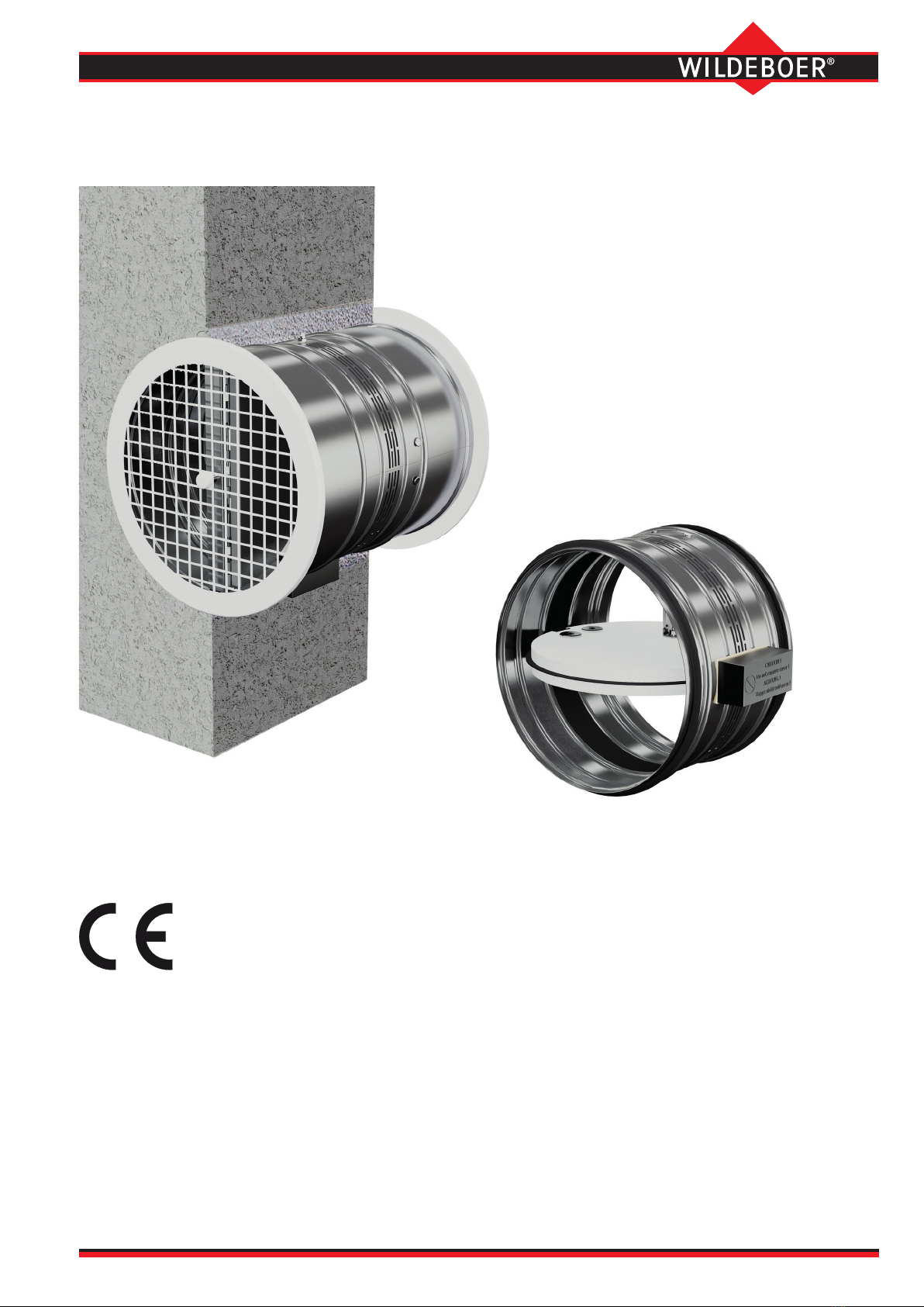
FR90 re dampers in short lengths
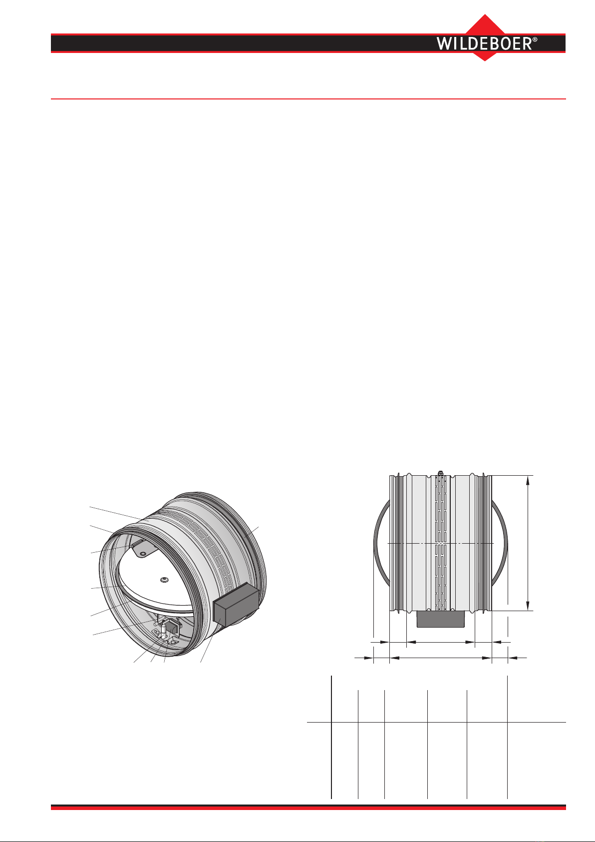
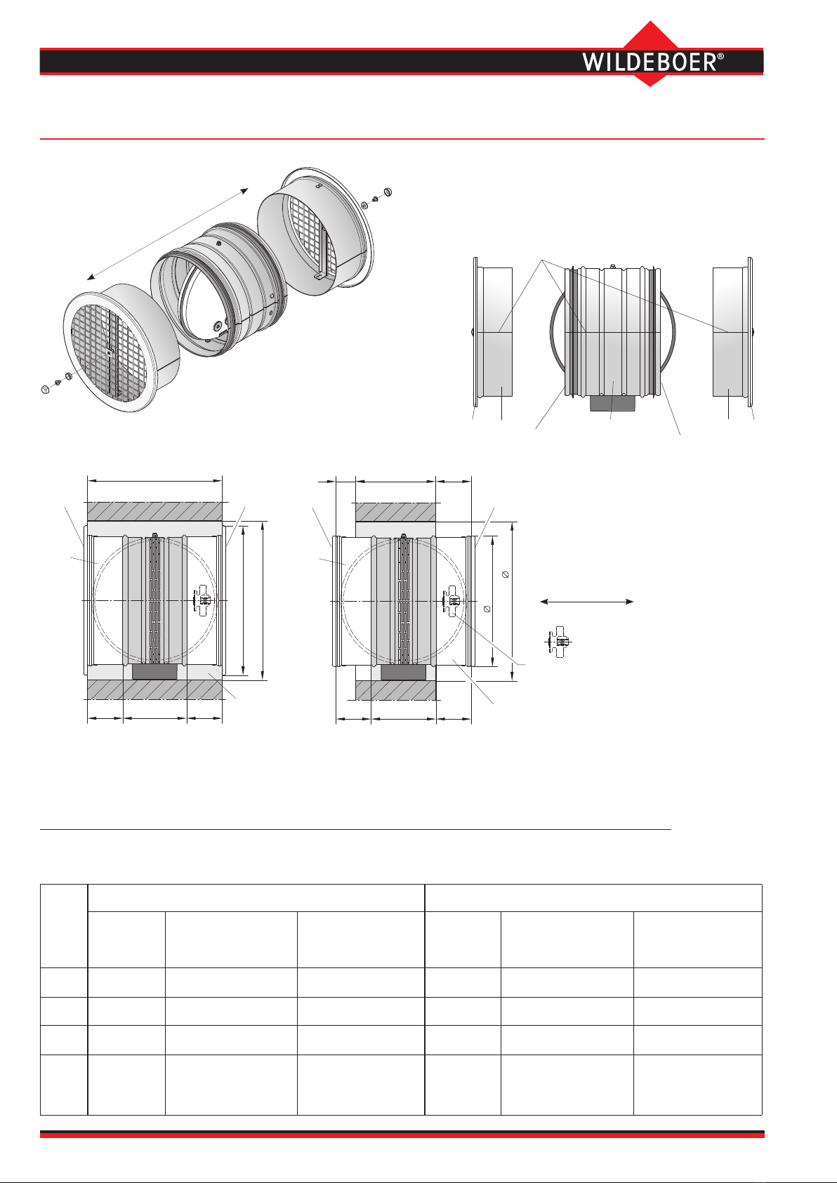
Description
1 Casing
2 Damper blade
3 Damper blade seal
4 Release element with
pipe fusible link 70°C
5 Fusible link holder
on the casing
6
Enclosed
closing spring actuator
7 Bearing axis
8 Plug connection with
lip seal
9 Limit switch (optional)
10 Fusible link holder on
damper blade
DN
Fire damper Protective
grille
Afree
[m2]
∅ d
[mm]
U
[mm]
AA
[m2]
Afree
[m2]
Weight
[kg]
100 99.3 00.0068 0.004 0.565 0.0049
125 124.3 00.0110 0.008 0.685 0.0081
160 159.3 5 0.0185 0.014 0.865 0.0138
200 199.3 25 0.0293 0.024 1.105 0.0221
250 249.3 50 0.0465 0.038 1.715 -
315 314.3 85 0.0747 0.064 2.415 -
Maintenance-free FR90 re dampers according to EN 15650: FR92K series, short length 150 mm
Fire classication: EI 30/60/90/120 (ve- ho, i ↔ o) S
Declaration of performance: DoP no.: CPR/FR90/003
• FR90 re dampers are essentially made from non-combustible building
materials. Certication: Certicate MPA-BS 6000/593/18
•Use in air transfer applications is based on compatibility for approval in accordance
with the building code in each individual case. Approvals are no longer issued.
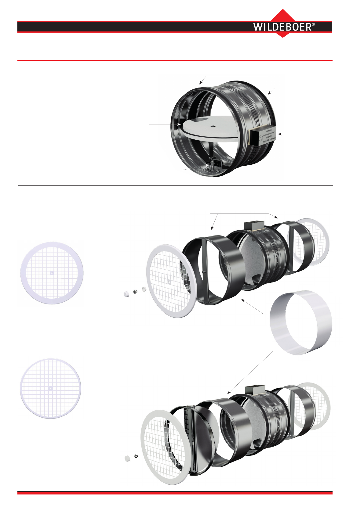
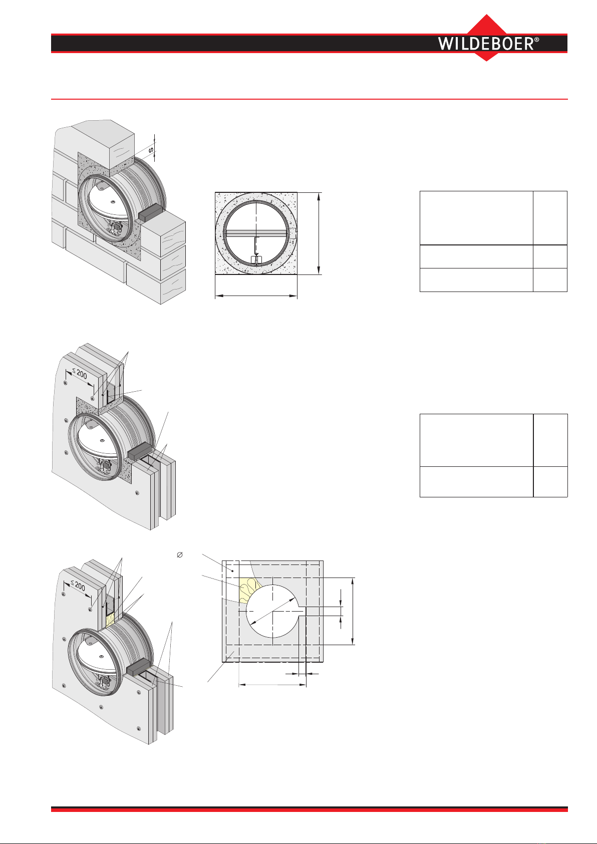
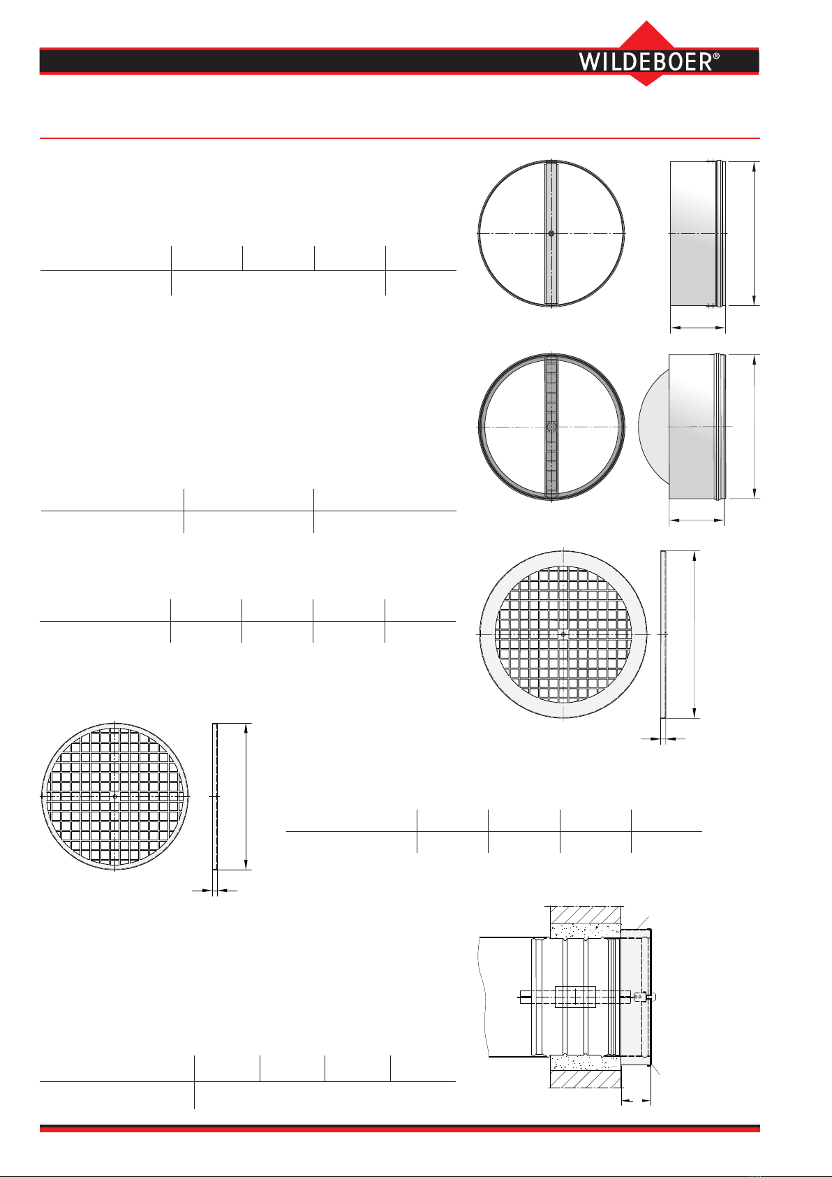
Optional accessories:
•Connecting piece AS with traverses for screw fastening
the protective grille SG1 or SG2 to the operation side
L1 or non-operation side L2. Sizes DN 100 to DN 200.
⇒ see pages 2 and 8 to 10
• Connecting piece AR with non-return valve and trav-
erse for screw fastening the protective grille SG1 or SG2
on the non-operation side L2. Sizes DN 160 to DN 200.
⇒ see pages 2, 8 to 10
•Protective grille SG1 with wide edge for installation
ush with the wall or in combination with the duct frame
RB. Sizes DN 100 to DN 200.⇒ see pages 2 and 8 to 10
•Protective grille SG2 with narrow edge for installation
ush with the connecting piece AS. Sizes DN 100 to
DN 200. ⇒ see pages 2, 8 to 10
•Duct frame RB for covering connecting piece and pro-
tective grille SG1 which protrude from the wall. Sizes
DN 100 to DN 200. ⇒ see pages 2 and 8 to 10
Single-piece casing made of galvanized sheet steel with
plug connections and lip seals on both sides.
Release element for 70°C nominal temperature.
Casing leak tightness class C according to EN 1751.
Enclosed, maintenance-free drive mechanism outside
the casing wall, sealed drive axles made of stainless
steel, with red metal bearings.
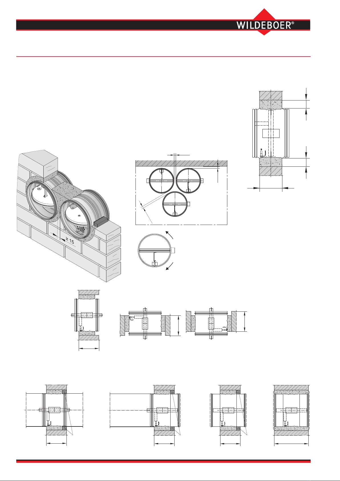
For installation in rigid walls and ceilings with a thickness
of at least 100 mm and in metal stud walls with a thick-
ness of 95 mm or more. Installation can be carried out
with the damper blade axis in the vertical or horizontal
position, or anywhere in between. Installation with the
connecting piece AR and non-return valve must be in a
vertical axis position.
Connection to ventilation ducts made from non-combus-
tible or combustible materials, or with protective grille.
Optional accessories:
•
Limit switch for damper blade position CLOSED. ⇒ see page 11
Nominal sizes DN [mm]
100 - 125 - 160 - 200 - 250 - 315