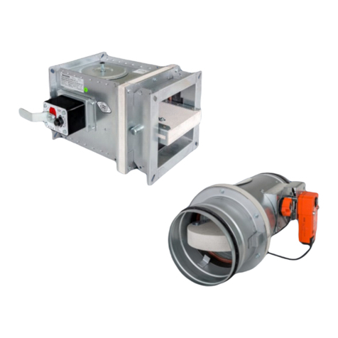
Wildeboer FK90 User manual

User Manual 5.02 (2016-10) 1Subject to change
Maintenance-free
FK90 re dampers - series FK120 -
■ Heights up to 1000 mm
■ Fire resistance period up to 120 minutes
Fire classication: EI 30/60/90/120 (ve- ho, i ↔ o) S C10ooo
■ Hygiene certicate
■ Environmental Product Declaration according to ISO 14025 and EN 15804
The German original version of this document shall prevail.

User Manual 5.0-2 (2016-10) 2 Subject to change
Series FK120
FK90 re dampers
Features and characteristics
Break-resistant damper blade
for vertical or horizontal installation,
with galvanized metal frame and
attached
elastomer lip seal
- frictionless sealing -
- replaceable -
Options:
Metal cover made of galvanized steel
Metal frame made of 1.4301 stainless steel
Metal frame and metal cover made of
1.4301 stainless steel
All-round enclosed
thermal release elements
70°C, 95°C or 100°C
Option:
Corrosion-resistant release element 70°C
Large free cross-section
Maximum volume ows
Minimum pressure drop
Extremely low sound
power level
Connection holes
for proles from 20 mm in height
Two control openings
(inspection openings)
for viewing both sides of the
damper blade
Thermal-mechanical
release mechanism
for manual single handed operation
Option:
Electric actuators, also explosion-protected
⇒ see page 5
Single-piece sheet steel casing
galvanized - pressure-joined - extremely
robust,
airtight
Leak tightness class C according to EN 1751
Option: Epoxy resin powder coating
Dimensions B and H in 5-mm increments
Nominal width B: 200 mm to 1500 mm
Nominal height H: 200 mm to 1000 mm
Lengths: 400 mm and 500 mm
Fully enclosed:
• Operation unit
• Release mechanism
•Release element

User Manual 5.02 (2016-10) 3Subject to change Series FK120
FK90 re dampers
Description
Increased corrosion protection through powder coating and stainless steel
Casings coated internally and externally are recommended:
•
metal frames of the damper blades made of 1.4301 stainless steel and
– if present – the metal cover as well
•
thermal-mechanical release mechanisms with corrosion-resistant (coated) release element 70°C.
These combinations allow additional corrosion protection for harsh service conditions.
FK90 re dampers
•
Meet the hygiene requirements according to VDI 6022-1, DIN 1946-4 and DIN EN 13779
•Do not promote the growth of microorganisms 1) (fungi, bacteria).
This reduces the risk of infection for people and also the necessary
cleaning and disinfection work!
•Are resistant to disinfectants 2)
•Are suitable for use in hospitals and similar facilities!
•
Permanently perform their function under high corrosion condi-
tions.Tested according to EN 15650, annex B with 20% saline solution.
1) The corresponding resistance of the materials to fungi and bacteria was veried by testing the microbial metabolic potential under
DIN EN ISO 846 for all materials in the FR90 re dampers.
2) The resistance to disinfectants of the materials in the FR90 re dampers was tested with the disinfectant groups of active ingredients alcohol and
quaternary compounds. These disinfectants are on the list by the Robert Koch Institute, and were used in accordance with the specications in
the list of disinfectants by the Disinfectants Commission in the German Association for Applied Hygiene (VAH). It has been veried that FR90 re
dampers can withstand normal use of disinfectants and disinfection methods.
Pressure-joined casing with all-round single-piece design,
made of galvanized sheet steel, leak tightness class C
according to EN 1751. Formed connection anges, outer
beading and tapered inner beading ensure stability, free-
dom of damper blade movement, minimum pressure drop
and low noise level.
Option: Casing with epoxy resin powder coating.
Replaceable damper blade made of high-temperature-re-
sistant, corrosion-resistant and abrasion-proof calcium
silicate with galvanized metal frame and folded, wear-re-
sistant elastomer lip seals.
Options: Damper blade with metal frame made of 1.4301
stainless steel/damper blade with metal cover made of
galvanized steel/damper blade with metal cover made of
1.4301 stainless steel.
Fully enclosed, maintenance-free slider crank transmis-
sion in the area of the casing wall, as a self-locking drive
mechanism for break-proof torque transmission. Sealed
drive axles made of stainless steel, with red metal bea-
rings.
Thermal release mechanisms for 70°C, 95°C and 100°C
nominal temperature. The operation units can be actua-
ted manually or electrically.
⇒ see pages 4 and 5
Release mechanisms, operation units and electric actu-
ators are enclosed and tted with a spring return. They are
maintenance-free, can be connected in a form-locking or
force-tting manner, are easy to replace and can be easily
retrotted as required.
For installation with horizontal or vertical damper blade
axles. Air inow from any connection side. Connection to
ventilation ducts made of non-combustible or combustible
materials, including protective grilles.
Option: Additional openings on the operation side in the
casing.⇒see page 14
Widths B: 200 mm to 1500 mm | 200 mm to 1000 mm
Heights H: 200 mm to 800 mm | 200 mm to 1000 mm
Lengths: 400 mm and 500 mm
The respective width and height dimensions are available
in 5-mm increments and can be combined. ⇒ see page 14
For installing in rigid walls, ceilings and in metal
stud walls. ⇒ see pages 11 and 12
Maintenance-free FK90 re dampers according to EN 15650
Fire classications: EI 30/60/90/120 (ve- ho, i ↔o) S C10ooo ⇒see page 11
Declaration of performance: DoP no.: CPR/FK120/002
EU Declaration of Conformity according to Directive 2014/34/EU
for use in potentially explosive atmospheres
Environmental Product Declaration ISO 14025, EN 15804: EPD-WWB-20130081-IBA1-DE

User Manual 5.0-2 (2016-10) 4 Subject to change
Series FK120
FK90 re dampers
Release mechanisms and actuators (1)
Thermal-mechanical release mechanism - standard -
with 70°C release element.
Option: with coated 70°C release element.
Option: with coated 95°C release element.
Option: with limit switch
E Changeover with gold-plated contacts for 5 A
at 250 V AC or 24 V DC; IP67;
1 m silicone-free connection cable, 3 x 0.34 mm².
One or two can be plugged in for the CLOSED and/or OPEN
position indicator; instead of blind caps.
Enclosed relea-
se element
can be replaced
from the front.
Blind cap can
be replaced with
the OPEN limit
switch.
Manual release
‘Red button’
Lever for opening the
re damper.
Inserted limit
switch CLOSED.
FK90 re dampers, series FK120, are tted with maintenance-free thermal-mechanical release mechanisms or with
thermal-electrical release mechanisms on the spring return actuators. Release occurs at a nominal temperature of
70°C. Coated release elements provide increased corrosion protection. Release mechanisms with a release element
for nominal temperatures of 95°C and 100°C are provided for warm air heating systems. The requirements for use in
ventilation systems for "cold smoke extraction" are country-specic.
Electric spring return actuators also close the re dampers if the supply voltage is interrupted. They reopen the re
dampers as soon as the voltage is present again.
Release mechanisms and operation units can be replaced on site!
Release mechanism and remote release with lifting solenoid
Option: with additional remote release based on the:
closed circuit principle. The re dampers must be opened
manually, and close after the electrical supply voltage is inter-
rupted.
GU24 with magnetic clamp 24 V DC; 1.6 W;
100% duty cycle; IP42.
WU220 with magnetic clamp 230 V AC; 4 VA;
100% duty cycle;IP42.
Open circuit principle. The re dampers must be opened
manually, and close by means of electrical or pneumatic stimu-
lus.
G24 with lifting solenoid 24 V DC; 3.5 W; 100% duty
cycle; IP42.
W220 with lifting solenoid 230 V AC; 5.5 VA; 100% duty
cycle; IP42.
P with lift cylinder 4 to 8 bar.
P2 with lift cylinder 1.2 to 8 bar.
Option: Electric spring return actuator - standard -
with 70°C release element; IP54.
M220-9/V 230 V AC; 9.2 VA; Imax ≤ 2 ms = 0.27 A.
M24-9/V 24 V AC/DC; 6.1 VA / 3.5 W;Imax ≤ 2 ms = 3.5 A.
Runtime: Opening ≈60 s, closing ≈21 s.
CLOSED/OPEN position indicators via limit switches for
5 A at ≤ 240 V AC.
Halogen-free connection cable; 0.9 m long; 2 x 0.75 mm²
and 6 x 0.75 mm². The AMP connector plugs are
detachable.
Option: with 100°C release element.
Enclosed release element

}
User Manual 5.02 (2016-10) 5Subject to change Series FK120
Option: Electric spring return actuator
with 70°C release element and terminal box.
EM-1 10 Nm
EM-2 15 Nm
RM-1 10 Nm
Power consumption up to 20 W including heating;
Irated ≤0.7 A; Imax ≤
1 ms
≈2.5 A
Runtime: Opening ≈30 s, closing ≈10 s.
CLOSED and OPEN position indicators via limit swit-
ches for ≤ 3 A at 24 V AC/DC and ≤ 0.25 A at 250 V
AC/DC; at least 5 V, 10 mA.
The 12 x 0.5 mm² halogen-free connection cable must be wired
in the terminal box! All of the contained voltages must be the
same!
Option: Electric spring return actuator
with 70°C release element; IP54.
M220-7 230 V AC; 7 VA/6 W; Imax ≤
10 ms
= 0.15 A.
M24-7 24 V AC/DC; 7 VA/5 W; Imax ≤
5 ms
= 5.8 A.
Runtime: Opening 40 to 75 s, closing ≈20 s.
CLOSED/OPEN position indicators via limit switches
for 0.5 A at ≤ 250 V AC or for 1 mA up to 3 A at 5 up to
250 V DC.
Halogen-free connection cable; 1 m long; 2 x 0.75 mm²
and 6 x 0.75 mm². The AMP connector plugs are
detachable.
Option: with 95°C release element.
Enclosed release element
The actuators can be rotated into suspen-
ded and vertical positions on site.
Terminal box
FK90 re dampers
Release mechanisms and actuators (2)
Thermal-mechanical release mechanism
with 70°C release element.
Option: with coated 70°C release element.
Option: with explosion-protected limit switch
E-Ex with normally open contact and normally closed
contact for 6 A at ≤ 250 V AC
or 0.25 A at ≤ 230 V DC; IP65;
2 m connection cable 4 x 0.75 mm².
One or two can be attached for the CLOSED and/or OPEN
position indicator.
- designs
Building area where a dangerous, potentially explo-
sive atmosphere may occur in normal operation...
... as a mixture of air and combustible gases, mists or vapours... ... in the form of a cloud of combustible dust contained in the air...
... occasionally ... temporarily or not at all. ... occasionally ... temporarily or not at all.
Zone 1 2 21 22
Identication of the re damper II 2 G c IIc T6/T5 II 3 G c IIc T6/T5 II -/2 D c T80°C/T95°C II -/3 D c T80°C/T95°C
Thermal-mechanical release mechanism with or
without explosion-protected limit switch X X *)X X *)
Motor drive EM-1 or EM-2 X X *)X X *)
RM-1 - X - X
Ambient temperatures: -20°C … +40°C for T6 and T80°C/-20°C … +50°C for T5 and T95°C *) Can also be used in this zone!
24 to 240 V AC/DC; IP66.
Use of explosion-protected designs
Enclosed release element
Enclosed relea-
se element

Release element
Lip seal
Damper
blade
Manual lever
Manual release
Casing
Control opening
Thermal-
mechanical
release mechanism
Limit switch
E-CLOSED (optional)
Manual release
Operation unit
Limit switch
E-OPEN (optional)
Closing spring
Control opening
Enclosed transmission
Operation side down
Operation side up
Connection flanges
only, if
only, if
Connection holes
User Manual 5.0-2 (2016-10) 6 Subject to change
Series FK120
Damper blade
• Operation side: K
•Non-operation side: K400, K500
L = 400 and L = 500
Height-independent excess lengths
T U J
Thermal-mechanical release
mechanism 95 - -
with: • W220, WU220 120
• G24, GU24 120 - -
•P, P2 105 - -
•E-Ex limit switch 105 - -
M220-9/V, M24-9/V 90 - -
M220-7, M24-7 145 40 -
EM-1, EM-2, RM-1 245 150 J3
Thermal-mechanical release mechanisms
are labelled with V1, V2, V4 and are mounted
based on the width B and height H of the re
dampers.
These size-dependent allocations must not
be changed on site!
H J3 K K400 K500
200 170 - - -
225 160 - - -
250 145 - - -
275 135 - 4 -
300 120 - 17 -
325 110 - 29 -
350 95 - 42 -
375 85 - 54 -
400 70 - 67 -
450 45 - 92 -
500 20 - 117 17
550 - - 142 42
600 - 7 167 67
650 - 32 192 92
700 - 57 217 117
750 - 82 242 142
800 - 107 267 167
850 - 132 292 192
900 - 157 317 217
950 - 182 342 242
1000 - 207 367 267
Additional space must be provided for assembly, electrical connections
and servicing; observe the cable entry points!
In addition to the "T" measurement, it is recommended that a distance of 400
mm be kept from adjacent walls, ceilings or other re dampers, in order to ensu-
re that the release mechanisms and actuators can be accessed for operational
purposes.
Connection anges are tted with connection holes. If additional holes are requi-
red for duct connection, these can be added on site!
H/B ≤400 > 400 to 750 > 750
≤300 V2 V4 V1
> 300 to 1000
FK90 re dampers
Data sheet (1) Dimensions
Maximum excess lengths of mechanical and electrical equipment parts.
Actuators
U horizontal (delivery condition)
J rotated to vertical or suspended position:
J3 EM-1, RM-1, EM-2

User Manual 5.02 (2016-10) 7Subject to change Series FK120
FK90 re dampers
Data sheet (2) Free cross-sections, weights
B/H 200 225 250 275 300 350 400 450 500 550 600 650 700 750 800 900 1000
200 0.018 0.022 0.026 0.030 0.034 0.041 0.049 0.057 0.065 0.073 0.080 0.088 0.096 0.104 0.112 0.127 0.143
225 0.021 0.026 0.030 0.035 0.039 0.048 0.057 0.066 0.075 0.084 0.093 0.102 0.111 0.121 0.130 0.148 0.166
250 0.024 0.029 0.034 0.039 0.044 0.055 0.065 0.075 0.086 0.096 0.106 0.117 0.127 0.137 0.147 0.168 0.189
275 0.027 0.033 0.038 0.044 0.050 0.061 0.073 0.085 0.096 0.108 0.119 0.131 0.142 0.154 0.165 0.188 0.212
300 0.030 0.036 0.042 0.049 0.055 0.068 0.081 0.094 0.106 0.119 0.132 0.145 0.158 0.170 0.183 0.209 0.234
325 0.033 0.040 0.047 0.054 0.061 0.075 0.089 0.103 0.117 0.131 0.145 0.159 0.173 0.187 0.201 0.229 0.257
350 0.035 0.043 0.051 0.058 0.066 0.081 0.097 0.112 0.127 0.143 0.158 0.173 0.188 0.204 0.219 0.250 0.280
375 0.038 0.047 0.055 0.063 0.071 0.088 0.105 0.121 0.138 0.154 0.171 0.187 0.204 0.220 0.237 0.270 0.303
400 0.041 0.050 0.059 0.068 0.077 0.095 0.112 0.130 0.148 0.166 0.184 0.201 0.219 0.237 0.255 0.290 0.326
450 0.047 0.057 0.067 0.078 0.088 0.108 0.128 0.149 0.169 0.189 0.209 0.230 0.250 0.270 0.291 0.331 0.372
500 0.053 0.064 0.076 0.087 0.098 0.121 0.144 0.167 0.190 0.212 0.235 0.258 0.281 0.304 0.326 0.372 0.418
550 0.059 0.071 0.084 0.097 0.109 0.135 0.160 0.185 0.210 0.236 0.261 0.286 0.312 0.337 0.362 0.413 0.463
600 0.064 0.078 0.092 0.106 0.120 0.148 0.176 0.203 0.231 0.259 0.287 0.315 0.342 0.370 0.398 0.454 0.509
650 0.070 0.085 0.101 0.116 0.131 0.161 0.191 0.222 0.252 0.282 0.313 0.343 0.373 0.404 0.434 0.494 0.555
700 0.076 0.092 0.109 0.125 0.142 0.174 0.207 0.240 0.273 0.306 0.338 0.371 0.404 0.437 0.470 0.535 0.601
750 0.082 0.100 0.117 0.135 0.152 0.188 0.223 0.258 0.294 0.329 0.364 0.400 0.435 0.470 0.505 0.576 0.647
800 0.088 0.107 0.125 0.144 0.163 0.201 0.239 0.277 0.314 0.352 0.390 0.428 0.466 0.503 0.541 0.617 0.692
850 0.093 0.114 0.134 0.154 0.174 0.214 0.255 0.295 0.335 0.376 0.416 0.456 0.496 0.537 0.577 0.658 0.738
900 0.099 0.121 0.142 0.163 0.185 0.228 0.270 0.313 0.356 0.399 0.442 0.484 0.527 0.570 0.613 0.698 0.784
950 0.105 0.128 0.150 0.173 0.196 0.241 0.286 0.332 0.377 0.422 0.467 0.513 0.558 0.603 0.649 0.739 0.830
1000 0.111 0.135 0.159 0.183 0.206 0.254 0.302 0.350 0.398 0.445 0.493 0.541 0.589 0.637 0.684 0.780 0.876
1050 0.117 0.142 0.167 0.192 0.217 0.268 0.318 0.368 0.418 0.469 0.519 0.569 0.620 0.670 0.720
1100 0.122 0.149 0.175 0.202 0.228 0.281 0.334 0.386 0.439 0.492 0.545 0.598 0.650 0.703 0.756
1150 0.128 0.156 0.184 0.211 0.239 0.294 0.349 0.405 0.460 0.515 0.571 0.626 0.681 0.737 0.792
1200 0.134 0.163 0.192 0.221 0.250 0.307 0.365 0.423 0.481 0.539 0.596 0.654 0.712 0.770 0.828
1250 0.140 0.170 0.200 0.230 0.260 0.321 0.381 0.441 0.502 0.562 0.622 0.683 0.743 0.803 0.863
1300 0.146 0.177 0.208 0.240 0.271 0.334 0.397 0.460 0.522 0.585 0.648 0.711 0.774 0.836 0.899
1400 0.157 0.191 0.225 0.259 0.293 0.361 0.428 0.496 0.564 0.632 0.700 0.767 0.835 0.903 0.971
1500 0.169 0.205 0.242 0.278 0.314 0.387 0.460 0.533 0.606 0.678 0.751 0.824 0.897 0.970 1.042
B/H 200 225 250 275 300 350 400 450 500 550 600 650 700 750 800 900 1000
200 10 11 11 12 12 13 14 15 15 16 17 18 19 19 20 22 24
225 11 11 12 12 13 13 14 15 16 17 18 19 19 20 21 23 24
250 11 12 12 13 13 14 15 16 17 17 18 19 20 21 22 24 25
275 12 12 13 13 13 14 15 16 17 18 19 20 21 22 23 24 26
300 12 13 13 13 14 15 16 17 18 19 20 21 22 22 23 25 27
325 12 13 13 14 14 15 16 17 18 19 20 21 22 23 24 26 28
350 13 13 14 14 15 16 17 18 19 20 21 22 23 24 25 27 29
375 13 14 14 15 15 16 17 19 20 21 22 23 24 25 26 28 30
400 14 14 15 15 16 17 18 19 20 21 22 23 24 26 27 29 31
450 15 15 16 16 17 18 19 20 21 23 24 25 26 27 28 30 33
500 15 16 17 17 18 19 20 21 23 24 25 26 27 29 30 32 35
550 16 17 17 18 19 20 21 23 24 25 26 28 29 30 31 34 36
600 17 18 18 19 20 21 22 24 25 26 28 29 30 32 33 36 38
650 18 19 19 20 21 22 23 25 26 28 29 30 32 33 35 37 40
700 19 19 20 21 22 23 24 26 27 29 30 32 33 35 36 39 42
750 19 20 21 22 22 24 26 27 29 30 32 33 35 36 38 41 44
800 20 21 22 23 23 25 27 28 30 31 33 35 36 38 39 42 46
850 21 22 23 24 24 26 28 29 31 33 34 36 38 39 41 44 48
900 22 23 24 24 25 27 29 30 32 34 36 37 39 41 42 46 49
950 23 24 25 25 26 28 30 32 33 35 37 39 41 42 44 48 51
1000 24 24 25 26 27 29 31 33 35 36 38 40 42 44 46 49 53
1050 24 25 26 27 28 30 32 34 36 38 40 42 43 45 47
1100 25 26 27 28 29 31 33 35 37 39 41 43 45 47 49
1150 26 27 28 29 30 32 34 36 38 40 42 44 46 48 50
1200 27 28 29 30 31 33 35 37 39 42 44 46 48 50 52
1250 28 29 30 31 32 34 36 38 41 43 45 47 49 51 54
1300 28 30 31 32 33 35 37 40 42 44 46 49 51 53 55
1400 30 31 32 34 35 37 40 42 44 47 49 51 54 56 58
1500 32 33 34 35 37 39 42 44 47 49 52 54 57 59 62
Free cross-sections Afree [m²]
Weights [kg] for the standard version
To be added on:
• Damper blade with
metal cover 10%
•Actuators:
M220-9/V; M24-9/V 2 kg
M220-7; M24-7 3 kg
EM-1; EM-2; RM-1 5 kg

6
5
55
3
2
120 30 50 70
7
200
250 300 350 400 500 600 700 800 1000 1200 1500
Height H [mm]
1
Pressure drop p [Pa]
S
3
4
8
10
12
2
Flow velocity v [m/s]
A
200
250
300
350
400
800
500
600
Width B [mm]
200
250
300
350
400
500
600
700
800
Height H [mm]
Volume flow V [m³/h]
225 275
200
300
400
600
800
1000
2000
3000
4000
6000
8000
10000
20000
30000
40000
50000
150
900
1000
900
1000
ooo050 40ooo30ooo20ooo10ooo
0
2500
3000
2000
1000
1500
500
]aP[kcurdsbeirteB
1400
1300
mm0051=B
1200
Metal damper blade B = 1500 mm
1400
v > 12 m/s
A
Volume flow [m³/h]
v > 12 m/s
A
Operating pressure
User Manual 5.0-2 (2016-10) 8 Subject to change
Series FK120
FK90 re dampers
Dimensioning (1) Pressure drop with ventilation duct connection on both sides
FK90 re dampers can be used in the area of the nomograms. With large dimensions, restrictions
should be taken into account depending on operating pressure and volume ow.
Example: At an operating pressure of 1500 Pa and a width of 1400 mm, the permissible volume ow is 26475 m³/h. This may increase if
the width is smaller or if the damper blade has a metal cover, or if an electric drive version is being used.

6
5
55
3
2
120 30 50 70
7
200
250 300 350 400 500 600 700 800 1000 1200 1500
Height H [mm]
1
Pressure drop p [Pa]
S
3
4
8
10
12
2
Flow velocity v [m/s]
A
200
250
300
350
400
800
500
600
Width B [mm]
200
250
300
350
400
500
600
700
800
Height H [mm]
Volume flow V [m³/h]
225 275
200
300
400
600
800
1000
2000
3000
4000
6000
8000
10000
20000
30000
40000
50000
150
900
1000
900
1000
User Manual 5.02 (2016-10) 9Subject to change Series FK120
FK90 re dampers
Dimensioning (2) Sound power level with ventilation duct connection on both sides
Example: ⇒ see page 10

ve sound power levelitaleR ]Bd[L
-20
+10
+5
0
-5
-15
-25
125 250 500 1000 2000 4000 8000
Octave mid frequency [Hz]
+15
-10
Flow velocity v [m/s]
A
63
-30
2
4
6
810
12
2
4
6
8
12
v [m/s]
A
User Manual 5.0-2 (2016-10) 10 Subject to change
Series FK120
FK90 re dampers
Dimensioning (3) Relative sound power level, examples, nomenclature
Relative sound power level
Example:
V = 4000 m³/h
B = 500 mm
H = 300 mm
AA = 0.150 m²
Afree = 0.098 m²
Dps = 29 Pa
v
A = 7.4 m/s
LWA = 47 dB(A)
Sound power level LW-Oct for the octave mid frequencies
f [Hz] 63 125 250 500 1000 2000 4000 8000
LWA [dB(A)] 47 47 47 47 47 47 47 47
DL7.4 m/s [dB] 5 6 1 -3 -6 -9 -15 -22
LW-Oct [dB] 52 53 48 44 41 38 32 25
B [mm] Width
H [mm] Height
AA [m²] Inow cross-section B x H
Afree [m²] Free cross-section
V [m³/h] Volume ow
vA [m/s] Flow velocity in inow cross-section
Dps [Pa] Static pressure drop
LWA [dB(A)] A-weighted, area-corrected sound power level
LW-Oct [dB] Octave sound power level LW-Oct = LWA + DL
DL [dB] Relative sound power level to LWA
f [Hz] Octave mid frequency
Nomenclature

Blind cap
E-CLOSED
Release mechanism
(always fitted on the H-side)
Control openings
(inspection openings)
No spacing required
Visible side
Visible side
Visible side
Visible side
User Manual 5.02 (2016-10) 11Subject to change Series FK120
Actuator on the left
Horizontal damper blade axle
Actuator below
Actuator on the right Actuator above
Actuator underneath the ceiling
Actuator above the ceiling
Vertical damper blade axle Horizontal damper blade axle
Vertical installation positions
Operation side Non-operation side
Operation side
Non-operation side
The release mechanisms and actuators are always located to the H-side on the casing of the re dampers ⇒ see page 6
FK90 re dampers
Installation in rigid walls and ceilings and in metal stud walls (1) with cladding on both sides
The re dampers are
EI 30/60/90/120 (ve- ho, i ↔o) S C10ooo
classied and labelled.
The eective re resistance period is
dependent on the installation.
Minimum thicknesses W, D [mm] are required:
All dimensions in mm
Fire resistance period in
minutes
30
60
90
120
Rigid walls 100 100
Rigid ceilings
•with H ≤ 800 and B ≤ 1500 100
115
Rigid ceilings
•with H > 800 and B ≤ 1000 115
Metal stud walls
with ≤ 1000 mm stud spacing 95 95
Horizontal installation positions
The drive positions of right, left, up and down all relate to the visible side.
Typical installation with mortar
in masonry walls.
"Flange-to-ange" installation.

1000≤1000≤1000≤1000≤1000≤
B
b
15≤
W, D 120≤
H
h
W, D > 120
„s“
≈05sib04
Two layer or multi-layer
wall cladding
Operation side
FK90 casing
W = 100
W 125≤
L=500
L=400
W > 125
to
User Manual 5.0-2 (2016-10) 12 Subject to change
Series FK120
FK90 re dampers
Installation in rigid walls and ceilings and in metal stud walls (2) with cladding on both sides
All dimensions in mm
Installation in rigid walls
Installation in rigid ceilings is carried out in the same way.
Installation in metal stud walls
Installation between supports Support interrupted
(trimmer)
Installation openings (examples)
The rigid walls and ceilings can be made of concrete, lightweight concrete, porous concrete (aerated concrete) or
plaster. They can be constructed as masonry or from wallboard. Walls may also be congured as re walls, shaft
walls, shafts or ducts.
Ceilings are generally made of concrete or aerated concrete in solid construction.
•Rigid walls and ceilingsmust have bulk density ≥ 450 kg/m³.
•Metal stud wallsshould be clad on both sides in two or more layers with 12.5-mm GKF plasterboard.
Installation openings produced from metal stud proles must be used as circumferential frames for installing the re
dampers. Cladding should be fastened to these using drywall screws ∅≥ 3.5 mm in ≤ 200 mm.
All frame parts should be joined to each other correctly and appropriately with respect to the type of wall. The top
and bottom frame parts must always be connected to the stud proles. Frames can also be congured as trimmers.
• Installation
is carried out
with mortar
of groups II or III according to DIN 1053 or with class M10 according to
EN 998-2 or with the corresponding re protection mortar or gypsum mortar.
•Minimum thicknesses
of walls,ceilings, and spacings
⇒ see table on page 11
•Recommended size ofinstallation opening b x h = (B + 80 to 100 mm) x (H + 80 to 100 mm).
The structural conditions should be taken into account by the customer, particularly when installing in metal stud walls.

Heating CLOSED OPEN
terminal box
Control voltages
to
Potential equation
(on site)
Control voltages
230 V AC or 24 V AC/DC
Cable
Cable
Fire damper
CLOSED OPEN
Control voltages
230
V AC or 24 V AC/DC
Cable
Cable
CLOSED OPEN
CLOSED OPEN
Fire damper
white
white
white
green
green
brown
brown
white
white
white
green green
brown brown
User Manual 5.02 (2016-10) 13Subject to change Series FK120
FK90 re dampers
Electrical connections, installation, functional testing, servicing
Actuators EM-1, EM-2 and RM-1Actuators M220-7, M24-7
Limit switches on thermal-mechanical release mechanisms
The CLOSED limit switches are actuated when the re damper is closed, and the OPEN
limit switches are actuated when the re damper is open.
Limit switch not actuated Limit switch actuated
Actuators M220-9/V, M24-9/V
Remote release
E-Ex limit switch
Installation
• FK90 re dampers, series FK120, must be installed based
on the instructions in this user manual. The technical
regulations and national statutory regulations must be obser-
ved during installation.
In Germany, this means the “Technical Building Regulations”
(VV TB) and the "Guideline on Fire Protection Requirements
Pertaining to Ventilation Systems" (Lüftungsanlagenrichtlinie -
LüAR).
FK90 re dampers meet these requirements and generally
recognised technical regulations.
•Electric wiring must be installed by the customer.
•Potential equalisation conductors to bridge exible
connection pieces on re dampers can be fastened
with metal screws if they are made of copper up to a
cross-section of 6 mm² or made of aluminium.
• Fire dampers in potentially explosive atmospheres must
be grounded in accordance with regulations.
Functional testing and servicing
• Fire dampers must be serviced by the owner and tested
periodically to ensure they are functioning correctly.
The intervals largely depend on the system operation. Rele-
vant regulations should be followed.
• FK90 re dampers, series FK120, are maintenance-free due
to fully enclosed components, corrosion-resistant materials
and precise manufacture.There is no need for regular clea-
ning and lubrication, which would otherwise be necessary.
• Functional tests on FK90 re dampers, series FK120, are
generally limited to a release and re-opening.This can be
performed remotely with electric actuators.
• Repairs or service work are required in the event of malfunc-
tions.Original spare parts must be used for this.
• Cleaning work required in ventilation systems for hygiene
reasons must be performed in an operation-dependent
manner, and also includes the re dampers.
Operating instructions for the FK90 re dampers, series FK120, can be downloaded online at www.wildeboer.de/en.
W220, G24
Closed during current ow
WU220, GU24
Closed during power interruption
Control voltages 230 V AC or 24 V DC
Limit switch not actuated
Connection cable colour coding
1 Thermostats, smoke detectors and switches
should only be installed if required.
On site delivery.
2 Thermal-electrical release element
70°C or 95°C; EM-1,
EM-2 and RM-1 only 70°C!
3 Thermal cut-o approx. 70°C
4 Electric actuator with limit switches for
OPEN-CLOSED position indicator.
The illustration shows the de-energised
operating position where the re dam-
pers are closed.
• The plugs on the connection cables can
be removed if they are not being used.
• Due to their in-built thermal release ele-
ments, all actuators must be stored at tem-
peratures not exceeding 50°C.
5 Switches or buttons for testing the actuators
6 Thermal-electrical release element 70°C or
100°C with plug-in connection for testing the
actuator.
7 Lifting solenoid
8 Magnetic clamp
The right to allow for variations in delivery from
the versions shown remains reserved.

User Manual 5.0-2 (2016-10) 14 Subject to change
Series FK120
FK120 - - - - - -
Size
B [mm] x H [mm] x L [mm]
⇒see page 3
Option: Damper blade
• Metal frame made of 1.4301
stainless steel
• Galvanized metal cover
• Metal frame and metal cover made of
1.4301 stainless steel
Metal frames/metal covers made of stainless steel should be
used with casings coated with epoxy resin.
⇒see page 3
Option: Casing design
• Casing with inner and outer epoxy
resin coating.
⇒see page 3
Option:
Additional casing openings
• 132-mm ∅
with cover;
position of the
opening:
top/bottom/top + bottom
Option: Release temperature
• 95°C or 100°C 1)
• 70°C corrosion protected 2)
⇒see pages 2 to 5
Option: Limit switches
• E-CLOSED
• E-OPEN
These limit switches can also be combined with the follow-
ing remote releases!
Option: Remote release
• GU24
• WU220
• G24
• W220
• P
• P2
Option: Explosion-protected
Option: Explosion-protected limit switch
• EX-CLOSED
• EX-OPEN
Option: Electric actuators
• M220-9/V
• M24-9/V
• M220-7
• M24-7
Option: Electric explosion-protected
actuators
• EM-1
• RM-1
• EM-2
⇒see pages 5 and 6
FK90 re dampers
Ordering FK90 re dampers, series FK120
1) only for actuators EM-1, EM-2, RM-1.
2) only for mechanical release mechanisms.
}Standard
200
225
250
275
300
325
350
375
400
450
500
550
600
650
700
750
800
850
900
950
1000
1050
1100
1150
1200
1250
1300
1400
1500
Heights H up to
1000 mm can be
combined with widths B
up to 1000 mm
Lengths L = 400 mm and 500 mm
All dimensions B and H can thus be combined!
}Standard
}Lifting solenoids
}Magnetic clamps
}Pneumatic cylinders
Heights H up to 800 mm can be
combined with widths B up to
1500 mm
}
also E-CLOSED together with E-OPEN
Only for thermal-mechanical release mechanisms
Actuators with thermal-electrical release
mechanisms and limit switches
}
also EX-CLOSED together with EX-OPEN
Standard widths B and heights H
Intermediate dimensions are available in
5-mm increments.

User Manual 5.02 (2016-10) 15Subject to change Series FK120
FK90 re dampers
Specication text
Maintenance-free re dampers according to EN 15650 with
30/60/90/120-minute re resistance period and the re classications
EI 30/90/90/120 (ve - ho, i ↔ o) S. C 10000. Air-tight casing, leak
tightness class C according to EN 1751, made of galvanized steel with
single-piece circumferential edging and pressure-joining, tapered inner
beading for freedom of damper blade movement, outer beading to ensure
comprehensive stability, and connection anges. Casing with epoxy resin
powder coating. Replaceable damper blade made of abrasion proof cal-
cium silicate, with folded, wear-resistant elastomer lip seals on a
prole frame made of galvanized steel/stainless steel and full cover
made of galvanized steel/stainless steel. Fully enclosed, main-
tenance-free drive mechanism in the area of the casing walls, with
self-locking slider crank for break-proof torque transmission. Sealed
drive axles made of stainless steel, with red metal bearings. Suitab-
le for installation with horizontal or vertical damper blade axles in
rigid walls and ceilings and in metal stud walls.
Enclosed maintenance-free thermal release mechanism 70C /95°C
or 100°C
•for manual single handed operation
•corrosion-resistant release element
•with (two) electrical limit switch(es) for signalling the damper
blade positions CLOSED/OPEN
•with remote release via magnetic clamp 230 V AC or 24 V DC/lifting
solenoid 230 V AC or 24 V DC/pneumatic cylinder
4 to 8 bar/1.2 to 8 bar.
•with electric actuator 230 V AC or 24 V AC/DC for remote control and
functional checks.
•explosion-protected for zones 1, 2, 21, 22
•with (two) electrical explosion-protected limit switch(es) for
signalling the damper blade positions CLOSED/OPEN
•with explosion-protected electric actuator for 24 V to 240 V AC/DC.
Tested according to 15650, annex B, with 20% saline solution,
for verication of permanent functioning under highly corrosive
conditions.
In order to comply with the hygiene requirements accor-
ding to VDI 6022-1, DIN 1946-4 and DIN EN 13779, vericati-
on of the necessary resistance of all materials to microor-
ganisms (fungi, bacteria) and disinfectant resistance.
With Environmental Product Declaration according to ISO 14025 and
EN 15804.
........ Pc Width: ....... mm
Height: ....... mm
Length: 400, 500 mm
Volume ow: ....... m³/h
Pressure drop: ....... Pa
Sound power level: ....... dB(A)
Manufacturer: WILDEBOER
Type/series: FK90/FK120
deliver: .........
install: .........
Select texts not highlighted in bold as required!

Complexity
Operating
costs
Wildeboer-Net
Operating
principle
Test
Cold
smoke
The solution:
Wildeboer Bauteile GmbH
Marker Weg 11 |26826 Weener (Germany) |+49 4951 950-0 |+49 4951 950-27120
info@wildeboer.de | www.wildeboer.de
Watch explanatory video
on YouTube
wildeboer.de/youtube
Network your fire protection and significantly minimise the cost of
planning, installation and testing. The BS2 communication system
“Wildeboer-Net” lays all the groundwork for you. Don’t miss out on
these benefits. We would be glad to advise you.
BS2 communication system
“Wildeboer-Net”
Optimum system solution combined with
our maintenance-free fire dampers
The system design, installation, programming and
commissioning of conventional control systems in
buildings is complex.
Special plug-and-play functionality allows control
systems for fire dampers to be designed, built and
connected in parent hierarchy without any measuring
and control know-how.
Preventing smoke spreading is a challenge. Detect smoke and close fire dampers reliably and in good
time via flexible release groups.
Recurring functional tests are time-consuming, affect
operation and incur high costs.
The BS2 communications system “Wildeboer-Net” performs
functional testing in less than 10 minutes in all.
Fire dampers have to operate reliably. Changes in the
building control system always require new operating
principle testing.
The BS2 communication system “Wildeboer-Net” controls
and safeguards the functioning of fire dampers. Changes
in the building control system have no effect.
BS2 communication system “Wildeboer-Net”
Our response:Existing problems:
Table of contents
Other Wildeboer Fire And Smoke Damper manuals