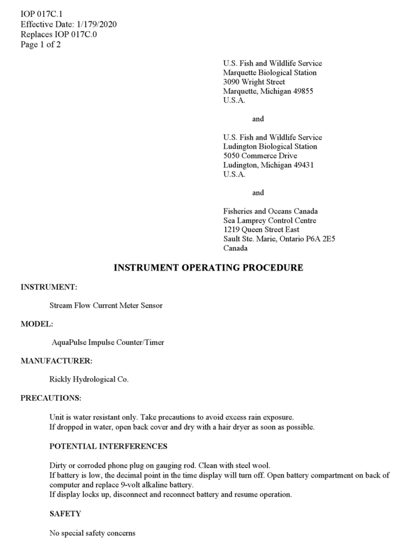
WILDLIFE 1001 User manual

IOP 007E.2
Effective Date: 2/02/2018
Replaces IOP 007E.1
Page 1 of 8
U.S. Fish and Wildlife Service
Marquette Biological Station
3090 Wright Street
Marquette, Michigan 49855
U.S.A.
and
U.S. Fish and Wildlife Service
Ludington Biological Station
5050 Commerce Drive
Ludington, Michigan 49431
U.S.A.
and
Fisheries and Oceans Canada
Sea Lamprey Control Centre
1219 Queen Street East
Sault Ste. Marie, Ontario P6A 2E5
Canada
INSTRUMENT OPERATING PROCEDURE
INSTRUMENT:
Handheld pH Meter
MODEL:
-Pro10 Meter (6050010)
-Cable (60510-1)
-pH Probe (1001)
-or for mobile laboratory applications cable + probe kit (1007)
MANUFACTURER:
Yellow Springs Instrument Co., Inc. (YSI)
PRECAUTIONS:
POTENTIAL INTERFERENCES
General –
-Greatest accuracy is achieved if the actual samples to be measured are within 10 ˚C of the
calibration solutions.
-Longer cable lengths introduce more error into the readings.
pH –
-Do not measure pH in metal containers.
-Water currents in streams can cause unstable readings.
-pH measurements will drift if the sample is not stirred.
-Do not expose the meter or probe to freezing temperatures.

IOP 007E.2
Effective Date: 2/02/2018
Page 2 of 8
-High humidity and cold temperatures may affect meter operation.
-Be sure that the temperature sensor is immersed in the sample.
-Buffers degrade from exposure to light - change daily.
SAFETY
No special precautions
PROCEDURES:
I. Components
A. Meter – The YSI Pro10 instrument includes internal hardware and software for
calculation of parameters, a display screen, and a keypad for data entry and screen
navigation.
B. Cable – The ruggedized cable connects the meter to the sensor. These cables are
designed for field applications and long lifetime.
C. Sensors – The cable includes a temperature sensor. A pH sensor is installed in the ISE
port of the cable.
D. For mobile laboratory applications, the pH/temp probe kit (1007) can be used in place of
the field grade cable and sensor.
II. Instrument setup
A. Battery installation and replacement
A battery symbol will blink in the lower, left corner of the display to indicate low
batteries when approximately 1 hour of battery life remains.
1. Use a screwdriver to remove the 4 screws securing the battery chamber cover.
2. Lift off the battery chamber cover.
3. Install two alkaline C-size batteries according to the inscribed battery symbols
on the inside of the battery chamber. Make sure batteries are in correct polarity.
4. Close the battery chamber cover and secure with the 4 screws.
5. Press and release the Power button ( ) on the keypad. The LCD will come on;
if not, consult the trouble shooting guide in the Pro10 User Manual.
6. Under normal conditions, the average battery life is 425 hours at room
temperature without using the back light. A battery symbol will blink in the
lower, left corner of the display to indicate low batteries when approximately 1
hour of battery life remains.
B. Sensor installation or replacement (not required for pH/temp probe kit 1007)
1. Locate sensor port on the 60510 cable.

IOP 007E.2
Effective Date: 2/02/2018
Page 3 of 8
2. If using the cable for the first time, remove the plastic plug from the cable’s
bulkhead port by pulling it straight out of the port. Otherwise, remove the old
sensor by unscrewing it from the bulkhead.
3. Ensure both the sensor connector and bulkhead connector are clean and dry.
4. Apply a small amount of grease to the o-ring.
5. Grasp the sensor with one hand and the cable bulkhead in the other.
6. Push the sensor into the connector on the cable until it is firmly seated with only
1 o-ring visible. Failure to properly seat the sensor may result in damage.
7. Twist the sensor clockwise to engage the threads and finger tighten. Do NOT
use a tool. This connection is water-tight.
8. The sensor is shipped with the tip in a storage bottle. To remove, twist the bottle
off the lid and remove the bottle from the sensor. Next, remove the o-ring and
slide the lid off the sensor.
C. Connecting the cable to the meter
1. To connect the cable, align the keys on the cable connector to the slots on the
instrument connector. Push together firmly and then twist the outer ring until it
locks into place. This connection is waterproof.
D. First Power on
1. Press the power/backlight key to turn the instrument on. The instrument will run
through a self-test and briefly display a splash screen
with system information.
2. The instrument will step through an initial
configuration when powered on for the first time to
select the language. Use the up or down arrow keys to
highlight the appropriate language, then press enter to
confirm. The language can be changed again in the
System Setup menu.
3. After initial configuration, the instrument will display
the Run Screen shown to the right.
E. Pro10 Key Pad Functions
Key Description
☼
Power and Backlight - Press once to turn instrument on. Press a second
time to turn backlight on. Press a third time to turn backlight off. Press and
hold for 3 seconds to turn instrument off.

IOP 007E.2
Effective Date: 2/02/2018
Page 4 of 8
Down Arrow - Use to navigate through menus, to navigate through box
options at the bottom of the Run screen and to decrease numerical inputs.
ENTER
Enter - Press to confirm selections, including alpha/numeric key
selections.
Up Arrow - Use to navigate through menus, to navigate through box
options along the bottom of the Run screen and to increase numerical
inputs.
Cal Calibrate - Press and hold for 3 seconds to calibrate. Opens Calibrate
menu from the Run screen.
Menu Menu - Press to enter the System Setup menu from the Run screen.
F. System Setup
Press the Menu key to access the System Setup menu. Use the up and down arrow keys
to scroll through setup options.
1. Audio – Disable audio by highlighting Audio and pressing enter. When
disabled, there will not be an ‘X’ in the box next to Audio.
2. Contrast – To adjust the display Contrast, use the up or down arrow keys to
highlight Contrast, then press enter. Next, use the up or down arrow keys to
adjust the contrast. The up arrow key will darken the contrast and the down
arrow key will lighten the contrast. After adjusting the contrast, press enter to
save and exit the Contrast adjustment function.
3. ISE Sensor Type – Use the up or down arrow keys to highlight ISE Sensor
Type, then press enter to open a submenu. Highlight the sensor type (pH, model
#1001) and press enter to confirm. The enabled sensor type will have an ‘X’ in
the box next to it. Use the down arrow key to highlight the ESC – Exit box, then
press enter to save changes and to close the sensor submenu.
4. ISE Units – Highlight ISE Units and press enter to open a submenu that allows
you to select the ISE units to be displayed on the Run screen. An enabled ISE
unit will have an ‘X’ in the box next to it. Highlight pH and press enter to enable
it. Highlight pH mV and press enter to enable it. pH mV is the sensor’s electrical
measurement signal before being converted into pH units. pH mVs can help you
determine if you are performing a good calibration and the condition of the pH
electrode. Highlight the ESC-Exit box along the bottom of the display and press
enter to save any changes and to close the ISE Units submenu.
5. Auto Stable – Auto Stable utilizes preset values to indicate when a reading is
stable. The preset values are adjustable in the System Setup menu. The user can
input a % change (0.0 to 9.9%) in measurement reading over ‘x’ amount of time
in seconds (3 - 19). The auto stable criteria is applied to the pH measurement or
the ORP mV reading depending on which sensor is enabled in the ISE Sensor
menu. When Auto Stable is enabled, an AS symbol will display next to the
reading on the Run screen and blink during stabilization. When the ISE reading
stabilizes based on the Auto Stable settings, the AS symbol will display steadily
and the instrument will beep twice if Audio is turned on. To enable Auto Stable,
highlight ISE Auto Stable, then press enter to open the submenu. Next, use the
up or down arrow keys to highlight the % change or seconds (secs) input field,
then press enter to make the highlighted field adjustable. Use the up or down
arrow keys to adjust the selected value, then press enter to confirm changes.

IOP 007E.2
Effective Date: 2/02/2018
Page 5 of 8
Once you have confirmed any changes, highlight the ESC-Exit box along the
bottom of the display and press enter to close the Auto Stable submenu. To
disable Auto Stable, set the % Change input to 0.0.
6. pH Buffer Set – Highlight pH Buffer Set and press enter to open a submenu
that allows you to select the Buffer Set used for auto buffer recognition during a
pH calibration. Highlight the USA buffer set option and press enter to enable.
The enabled buffer set will have an ‘X’ in the box next to it. Highlight the ESC-
Exit box and press enter to save any changes and to close the submenu.
7. Temperature Units – Highlight Temperature Units and press enter to open a
submenu that allows you to change the temperature units displayed on the Run
screen. Highlight Celsius and press enter to enable. The enabled temperature
unit will have an ‘X’ in the box next to it. Highlight the ESC-Exit box and press
enter to save any changes and to close the Temperature Units submenu.
8. Auto Shutoff - Auto Shutoff allows you to set the instrument to turn off
automatically after a period of time since the last button press. In the setup
menu, use the up or down arrow keys to highlight Auto Shutoff, then press enter
to open the submenu. Press enter while the minute field is highlighted to make it
adjustable. Next, use the up or down arrow keys to adjust the shut off time to 15
minutes. Press enter to save the new shutoff time. Next, highlight the ESC-Exit
box and press enter to close the submenu.
III. Calibration
A. Temperature – All Pro10 cables have built-in temperature sensors. Temperature
calibration is not required nor is it available.
B. pH - The Pro10 pH sensors can be calibrated by performing a 1, 2 or 3-point calibration.
A minimum of 2 point calibration is required for quality assurance purposes in the SLCP.
At least one of the calibration points must be done with pH 7 buffer. For auto buffer
recognition to work properly with an older or dirty sensor, calibrate in pH 7 buffer first.
For highest accuracy, use fresh, traceable pH buffers and ensure the sensor and
calibration cup are clean. Most applications in the SLCP use a two point calibration:
1. Place the sensor in pH 7 buffer and allow the temperature and pH readings to
stabilize for at least 5 minutes.
2. Press and hold Cal for three seconds.
3. Highlight pH and press enter. If pH is not listed as an option, check the System
Setup menu to ensure pH is enabled in the ISE Sensor Type menu.
4. Highlight 2 point and press enter.
5. If necessary, use the up and down arrow keys to adjust the pH buffer value. Note
the pH mV reading which ideally should be between -50 and +50 in pH 7 buffer.
If the pH mV reading is outside of this range, clean the sensor as described in
the maintenance section of this protocol.
6. Press enter to continue to second point.
7. Rinse the sensor and place it in the second pH buffer (4 for alkalinity
measurements or 10 for stream pH measurements).
8. If necessary, use the up and down arrow keys to adjust the pH buffer value.

IOP 007E.2
Effective Date: 2/02/2018
Page 6 of 8
9. Wait at least 5 minutes for the pH sensor to stabilize and for the temperature
reading to stabilize. Note the pH mV reading. pH mVs in buffer 4 should be
+159 to 180 mV from the previous buffer 7 pH mV value. pH mVs in buffer 10
should be -159 to 180 mV from the previous buffer 7 pH mV value. If the mV
readings are outside of these ranges, clean the sensor as described in the
maintenance section of this protocol.
10. Press enter to complete the calibration or press Cal to cancel.
11. ‘Calibration Successful’ will display for a few seconds to indicate a successful
calibration and then the instrument will return to the Run screen.
12. If the calibration is unsuccessful, an error message will displayon the screen.
Press the Cal key to exit the calibration error message and return to the Run
screen. See the Troubleshooting section of this manual for possible solutions.
pH Values of Standard Buffers with Temperature
Temperature oC
pH buffer
0
10
20
30
4.00
4.00
4.00
4.00
4.01
7.00
7.12
7.06
7.02
6.99
10.00
10.31
10.17
10.05
9.95
IV. Calibration check
A. A complete calibration check is conducted approximately every two hours, if ambient
temperature has changed considerably, at shift change, at the end of the working day, and
at any time that results are suspect. The procedure for this check varies from the initial
calibration. The meter is not recalibrated; the standards are treated as water samples.
B. Rinse the sensor in deionized water, pat dry with lab wipe tissue, and then immerse in
one of the buffers. After at least 5 minutes and once the values stabilize, record the
measurement. Record the pH and temperature in the instrument log book.
C. Rinse the sensor in deionized water, pat dry with lab wipe tissue and immerse in the
second buffer. Measure the pH according to the procedure followed in step B. Record
the pH and temperature in the instrument log book.
V. Measurements
pH readings are typically quick and accurate. However, it may take sensors a little longer to
stabilize if they become coated or fouled. To improve the response time of a sensor, follow the
cleaning steps in the Maintenance section of User manual.
A. Ensure the cable/probe is connected to the meter.
B. Be sure the meter has been calibrated.
C. For in stream measurements, install the sensor guard to protect the sensor. The sensor
guard need not be used for measurements in sample bottles.

IOP 007E.2
Effective Date: 2/02/2018
Page 7 of 8
D. Place the probe in the sample to be measured. Be sure the sensors are completely
submerged in the sample (note that the temperature sensor is at the top of the pH sensor).
E. Give the probe a quick shake to release any air bubbles.
F. Allow temperature reading to stabilize.
G. Stir the sample water with the probe at a moderate pace.
H. After at least 5 minutes and once the values stabilize, record the measurement.
VI. Storage of the pH sensor
A. During preliminary water chemistries, the sensor attached to the cable can be stored in
the humidity chamber containing a moistened sponge between measurements.
B. At all other times if the sensor is not being used to take repeated measurements, store the
sensor in pH 4 buffer solution in the supplied storage bottle.
MAINTENANCE:
I. Routine cleaning at the end of each treatment session or when pH response is slow
A. Use clean water and a soft clean cloth, lens cleaning tissue, or cotton swab to remove all
foreign material from the glass bulb or platinum button. Then use a moistened cotton
swab to carefully remove any material that may be blocking the reference electrode
junction of the sensor.
B. Soak the sensor for 10-15 minutes in clean water (Not DI water. Soaking in DI water will
shorten the life span of the probe) containing a few drops of commercial dish washing
liquid. Gently clean the glass bulb and platinum button by rubbing with a cotton swab
soaked in the cleaning solution. Rinse the sensor in clean water, wipe with a cotton swab
saturated with clean water, and then re-rinse with clean water.
II. Additional cleaning when good pH response is not restored using Step I
A. Soak the sensor for 30-60 minutes in one molar hydrochloric acid. Rinse the sensor in clean
water, wipe with a cotton swab saturated with clean water, and then re-rinse with clean water.
To be certain all traces of acid are removed, soak the sensor in clean water (Not DI water.
Soaking in DI water will shorten the life span of the probe) for about an hour with occasional
stirring.
B. If biological contamination of the reference junction is suspected or good response is not
restored, soak the sensor for approximately 1 hour in a 1:1 dilution of household chlorine
bleach. Rinse the sensor with clean water and then soak for at least 1 hour (more if
possible) in clean water (Not DI water. Soaking in DI water will shorten the life span of
the probe) with occasional stirring to remove residual bleach from the junction. Then re-
rinse the sensor with clean water and retest.
III. For additional troubleshooting, see user manual.
REFERENCE:
User Manual for YSI Pro 10
Calibration Tips for YSI Professional Plus Multiparameter Water Quality Meter

Jessica M. Barber
Digitally signed by
JESSICA BARBER
Date: 2020.03.10
10:57:48 -04'00'
This manual suits for next models
3
Table of contents
Other WILDLIFE Measuring Instrument manuals
Popular Measuring Instrument manuals by other brands

Domino
Domino F520i user guide

Orion
Orion 24792 user manual

Rohde & Schwarz
Rohde & Schwarz ZN-Z15 Series user manual

Underground Magnetics
Underground Magnetics Mag 6 Series Getting started

Hanna Instruments
Hanna Instruments Nitrite Low HI 707 quick start guide

Reply
Reply Sidekick Pre-Installation Design Guide