Wilfley SolidLock User manual

5870 E. 56th Avenue, Commerce City, CO 80022 USA • Toll Free: 1-800-525-9930 • Phone: +1 (303) 779-1777 • Fax: +1 (303) 779-1277 • www.wilfley.com • pumps@wilfley.com
IM-SL rev 6 2
Table of Contents
FOREWORD ..............................................................................................................................................................3
1.0 SEAL DESCRIPTION ..........................................................................................................................................4
1.1 STANDARD CONFIGURATION ............................................................................................................................5
1.2 PURGE PORT CONFIGURATION.........................................................................................................................6
2.0 PRE-INSTALLATION...........................................................................................................................................7
3.0 SETTING THE SEAL –SOLIDLOCK..................................................................................................................8
4.0 SPRING NUMBER ...............................................................................................................................................9
4.1 SPRING SPACING...............................................................................................................................................9
4.2 ADJUSTING PERFORMANCE..........................................................................................................................10
5.0 ROTARY SEAL SUBASSEMBLY.....................................................................................................................11
5.1 ROTARY SEAL ASSEMBLY STEP 2...................................................................................................................12
6.1 STATIONARY SEAL –A7/A9 CHEMICAL PUMP............................................................................................13
6.2 STATIONARY SEAL - AF CHEMICAL PUMP..................................................................................................14
6.3 STATIONARY SEAL - EMW® SLURRY PUMP ...............................................................................................15
6.4 STATIONARY SEAL - HD SLURRY PUMP .....................................................................................................17
6.5 STATIONARY SEAL - KPRO®SLURRY PUMP ..............................................................................................18
6.6 STATIONARY SEAL - S3 CHEMICAL SLURRY PUMP...................................................................................20
7.0 RECOMMENDED SPARES...............................................................................................................................22
8.0 REVISION HISTORY .........................................................................................................................................23

5870 E. 56th Avenue, Commerce City, CO 80022 USA • Toll Free: 1-800-525-9930 • Phone: +1 (303) 779-1777 • Fax: +1 (303) 779-1277 • www.wilfley.com • pumps@wilfley.com
IM-SL rev 6 3
Foreword
This manual contains instructions and guidelines for the assembly of the Wilfley SolidLock®static seal cartridge.
The information contained herein is meant to serve only as a general guideline. If detailed questions or problems
arise, contact Wilfley or your authorized Wilfley representative.
Use of the equipment on a service other than what was specified at the time of purchase could void the warranty
unless Wilfley has provided written approval otherwise.
To assure proper installation, supervision from an authorized Wilfley representative is recommended.
A.R. Wilfley and Sons, Inc. shall not be liable for damage or delays caused by a failure to observe the
instructions that are contained in this manual.
Warranty is only valid when genuine Wilfley parts are used. Contact your authorized Wilfley representative
for basic warranty information and before making any changes.
Proper pump selection should be made for applications based on conditions of service, material compatibility,
solids content, fluid temperature, footprint size, as well as motor speed and energy considerations. Improper
selection or improper use of pumps could risk injury or damage. For maximum safety and reliability, use only
factory-supplied parts and closely follow all operating instructions and maintenance recommendations.

5870 E. 56th Avenue, Commerce City, CO 80022 USA • Toll Free: 1-800-525-9930 • Phone: +1 (303) 779-1777 • Fax: +1 (303) 779-1277 • www.wilfley.com • pumps@wilfley.com
IM-SL rev 6 4
1.0 Seal Description
Wilfley Centrifugal pumps have a shaft seal designed for performance and dry running in a broad variety of
applications called the Solidlock®static Seal. For pumping applications with abrasives and some degree of solids
or particulates that tend to crystalize, the Solidlock seal is an excellent solution. The two seal faces operate as a
dynamic seal in tandem with the pump’s expeller.
Upon start up, centrifugal forces act upon governor weights to physically separate the seal faces during rotation.
This means there is no seal drag during operation, no wear or rubbing of parts or seal faces. At shut down,
isolated springs force the seal faces to close prior to the transition of dynamic sealing to static sealing. The soft
stationary seal face will flex outwards against the harder rotary seal face to eliminate leakage of internal pressure.
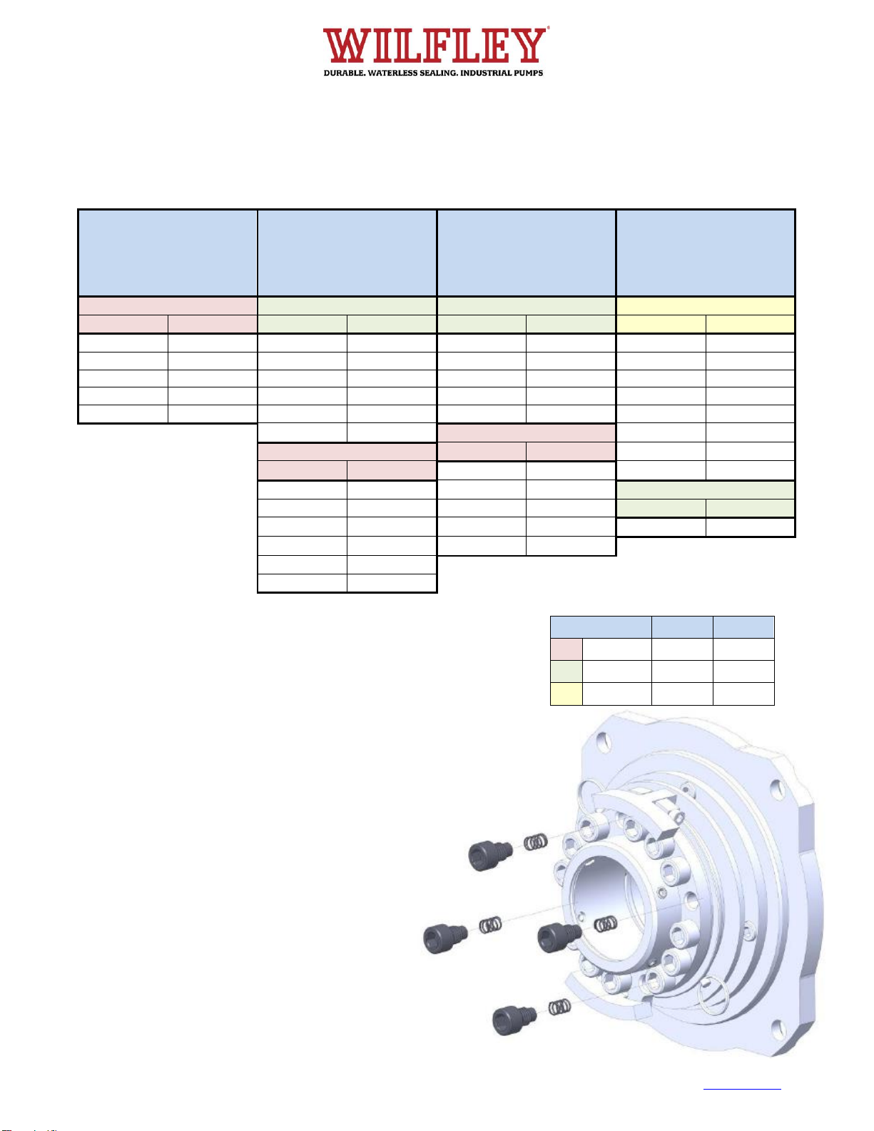
The major components of the seal are the rotary seal assembly and the stationary
seal. As indicated by their names, the stationary seal stays fixed in position, and the
rotary seal rotates with the shaft of the pump.
The basis of performance is the static seal face which is designed to pull inward via
the suction created by the expeller. This seal is optimum for slurry applications which
will still seal with particles between the sealing faces because of the combination of
seal faces.
A matched set of springs and governor weights are used in combination to open and
close the seal at specifically designed speeds based on the customer’s application.
No flushing plan is required and the Solidlock®seal may operate dry without issue,
such as if a tank level is dropped accidentally. The cartridge design allows the units
to be installed easily and quickly, offering installation in many Wilfley pump families.
The life of the seal is dependent upon the correct placement of the seal based on
suction pressure, pump speed and characteristics of the pumping liquid. With the
correct selection of materials, the unit will be able to accommodate up to 400 degrees
Fahrenheit applications.
Since chemical processes are all unique, the construction material for the Solidlock®
components should be reviewed for compatibility with the pumped liquid.
Seal Name
Seal
Type
Runs
Dry
Solids
Crystallizing
liquids
Vapors
High
Temp.
Solidlock®Seal
Dynamic
(with Expeller)
Yes
Yes
Yes
No
No

5870 E. 56th Avenue, Commerce City, CO 80022 USA • Toll Free: 1-800-525-9930 • Phone: +1 (303) 779-1777 • Fax: +1 (303) 779-1277 • www.wilfley.com • pumps@wilfley.com
IM-SL rev 6 5
1.1 Standard Configuration
Ref. #
Description
Qty.
S1A
Stationary Seal Housing
1
S1D
Stationary Seal
1
S1E
Seal Lock
1
S1F
Stationary Seal Bolt
3-8
S2A
Rotary Seal
1
S2B
Rotary Seal Bolt
4
S2C
Rotary Seal Carrier
1
S2D
Weight Spider
1
S2E
Weight
2
S2F
Spring Bolt
TBD1
S2G
Spring
TBD1
S2H
Pull Pin
2
S2J
Weight Bolt
2
S2K
O-Ring, Rotary Seal
1
S2L
O-Ring, Rotary Seal Carrier
1
S2M
O-Ring, Weight Spider
1
S2N
O-Ring, Weight Spider to Shaft Sleeve
1
S2P
Shaft Sleeve Set Screw
4
See
Table
Shaft Sleeve
1
1. Quantity varies with pump size and operating
speed.
Not all components are used on each pump model.
Shaft Sleeve Ref. Numbers:
Model
Ref. #
A7
39
A9
5A
AF
14
EMW®
14
HD
17
Kpro®
19C
S3
39

5870 E. 56th Avenue, Commerce City, CO 80022 USA • Toll Free: 1-800-525-9930 • Phone: +1 (303) 779-1777 • Fax: +1 (303) 779-1277 • www.wilfley.com • pumps@wilfley.com
IM-SL rev 6 6
1.2 Purge Port Configuration
Ref. #
Description
Qty.
S1A
Stationary Seal Housing
1
S1D
Stationary Seal
1
S1E
Seal Lock
1
S1F
Stationary Seal Bolt
3-8
S1H
Lip Seal
1
S2A
Rotary Seal
1
S2B
Rotary Seal Bolt
4
S2C
Rotary Seal Carrier
1
S2D
Weight Spider
1
S2E
Weight
2
S2F
Spring Bolt
TBD1
S2G
Spring
TBD1
S2H
Pull Pin
2
S2J
Weight Bolt
2
S2K
O-Ring, Rotary Seal
1
S2L
O-Ring, Rotary Seal Carrier
1
S2M
O-Ring, Weight Spider
1
S2N
O-Ring, Weight Spider to Shaft Sleeve
1
S2P
Shaft Sleeve Set Screw
4
See
Table
Shaft Sleeve
1
1. Quantity varies with pump size and operating
speed.
Not all components are used on each pump model.
Shaft Sleeve Ref. Numbers:
Model
Ref. #
A7
39
A9
5A
AF
14
EMW®
14
HD
17
Kpro®
19C
S3
39
Back up and sealing of vapors is possible on select product lines.

5870 E. 56th Avenue, Commerce City, CO 80022 USA • Toll Free: 1-800-525-9930 • Phone: +1 (303) 779-1777 • Fax: +1 (303) 779-1277 • www.wilfley.com • pumps@wilfley.com
IM-SL rev 6 7
2.0 Pre-Installation
1. Assemble pump according to the pump IOM manual until the step to install the seal is reached.
2. Slide the rotary seal subassembly onto the pump shaft so that the weights and bolts face the bearing frame.
Do not tighten the four set screws (S2P) on the subassembly yet.
3. Install stationary seal subassembly onto the pump so that the stationary seal (S1D) is facing the recently
installed rotary seal assembly.
4. Complete final assembly of the pump according to the pump IOM manual –this will include setting the impeller
clearances and final position of the shaft.
5. Set seal according to section 3.0 Setting the Seal.
*Stationary seal subassembly varies by pump model (Kpro®shown above)

5870 E. 56th Avenue, Commerce City, CO 80022 USA • Toll Free: 1-800-525-9930 • Phone: +1 (303) 779-1777 • Fax: +1 (303) 779-1277 • www.wilfley.com • pumps@wilfley.com
IM-SL rev 6 8
3.0 Setting the Seal –Solidlock
The seal MUST be adjusted and locked AFTER the pump has been assembled AND the impeller clearance has
been set according to pump IOM. Before you begin, ensure that the set screws (S2P) are loose and that the rotary
seal subassembly can freely move axially along the shaft sleeve.
1. Firmly push the rotary seal subassembly against
the stationary subassembly until the seal faces
come into contact.
2. Evenly tighten the four set screws (S2P) to lock
the position of the rotary seal subassembly to the
shaft.
3. Pull the two pins (S2H) out of the rotary seal
subassembly. It may be necessary to pull on the
weights (S2E) or push the assembly slightly to be
able to pull out the two pins (S2H).
The seal should be ready for use. One way to verify
this is to check that the shaft has become more
difficult to turn since the seal faces are engaged with
each other.
When resetting pump clearances, performing
maintenance, or disassembling the pump, the rotary
seal subassembly must be reset by reinstalling the pull
pins (S2H). Pulling up on the weight (S2E) nearest the
hole with the pin (S2H) will help line up the two radial
holes. Once both pins (S2H) are in, the set screws
(S2P) may be loosened and the rotary seal
subassembly may be adjusted or disassembled from
the pump.

5870 E. 56th Avenue, Commerce City, CO 80022 USA • Toll Free: 1-800-525-9930 • Phone: +1 (303) 779-1777 • Fax: +1 (303) 779-1277 • www.wilfley.com • pumps@wilfley.com
IM-SL rev 6 9
4.0 Spring Number
The Solidlock spring number depends on the weights used and the pump model. There are three weight sizes
possible. Use the table to determine the quantity of springs required for your application. If you are using a
variable frequency drive and are operating the pump as various speeds, use your lowest operating speed to
determine the quantity of springs.
1A7 –2A7
1A9 –2A9
1AF –4AF
EMW50 –EMW75
1Kpro –3Kpro
3A7 –4A7
3A9
EMW100
4Kpro –5Kpro
4A9 –5A9
EMW150
6Kpro
1S3
EMW200 –EMW250
HD8x4 –HD8x6
8Kpro
2S3
Small Weight
Medium Weight
Medium Weight
Large Weight
Speed
Spring Qty.
Speed
Spring Qty.
Speed
Spring Qty.
Speed
Spring Qty.
< 1,400
4
< 600
6
< 600
4
< 400
4
1,400-1,600
6
600-800
8
600-700
8
400-500
6
1,600-1,800
8
800-900
10
700-800
12
500-600
8
1,800-2,000
10
900-1,000
12
800-900
14
600-700
10
> 2,000
12
1,000-1,100
14
900-1,100
16
700-800
12
1,100-1,200
16
Small Weight
800-900
16
Small Weight
Speed
Spring Qty.
900-1,000
20
Speed
Spring Qty.
1,100-1,300
8
1,000-1,100
24
1,200-1,400
6
1,300-1,500
10
Medium Weight
1,400-1,700
8
1,500-1,700
12
Speed
Spring Qty.
1,700-2,000
10
1,700-1,900
14
> 1,100
24
2,000-2,200
12
> 1,900
16
2,200-2,400
14
> 2,400
16
SolidLock assemblies are shipped with the correct quantity of springs
and weight size for your application. Identification of springs and weights
may be found on the etched part number or the overall width from end to
end. Altenatively, the part number may eb found on the Pump Card or
Bill of Materials listing. For clarification, Wilfley will be able to identify the
size and number if the pump serial number is identified.
4.1 Spring Spacing
Spring selection must be completed before
assembly. During assembly, it is important for
proper seal performance and actuation that the seal
springs (S2G) be spaced evenly throughout the bolt
pattern. As shown, this size seal assembly uses
four springs. They are evenly spaced between the
sixteen spring bolts (S2F).
It is also important that they be tightened in a criss-
cross or star pattern to prevent any misalignment or
cocked seal faces. As a visual indicator, all bolts
should be bottomed to the same height.
WEIGHT SIZE
Part #
Length
Small
A3193
2.6”
Medium
A3199-02
3.2”
Large
A3199
4.3”

5870 E. 56th Avenue, Commerce City, CO 80022 USA • Toll Free: 1-800-525-9930 • Phone: +1 (303) 779-1777 • Fax: +1 (303) 779-1277 • www.wilfley.com • pumps@wilfley.com
IM-SL rev 6 10
4.2 Adjusting Performance
The Solidlock seal may be fine-tuned for specific customer applications with the ability to change the seal opening
and closing speeds. Spring bolts and springs may be added or removed to change the speed at which the seal
faces open and close. Adding springs will make the seal close more quickly as the pump slows down but also
take longer to open. Subtracting springs will make the seal open faster but take longer to close during shutdown.
Shown below is the standard spring number by speed for the smallest size of the Solidlock seal. Follow the
spring recommendations in Section 4.0 Spring Number or consult a Wilfley representative for additional opening
and closing adjustment.

5870 E. 56th Avenue, Commerce City, CO 80022 USA • Toll Free: 1-800-525-9930 • Phone: +1 (303) 779-1777 • Fax: +1 (303) 779-1277 • www.wilfley.com • pumps@wilfley.com
11 IM-SL rev 6
5.0 Rotary Seal Subassembly
1. Install o-ring (S2K) into the rotary seal (S2A).
2. Install o-ring (S2L) into bore of the rotary seal
carrier (S2C).
3. Insert rotary seal (S2A) into the rotary seal carrier
(S2C) attaching them with bolts (S2B).
4. Insert o-ring (S2N) into the bore on the weight
spider (S2D), and o-ring (S2M) onto the outer
diameter groove of the weight spider (S2D).
5. Loosely install set screws (S2P) into the weight
spider (S2D).
6. Insert weight spider (S2D) into the rotary seal carrier (S2C) in the orientation shown above, making sure the
two sets of radial holes line up with each other.
Ref. #
QTY.
DESCRIPTION
S2A
1
Rotary Seal
S2B
4
Rotary Seal Bolt
S2C
1
Rotary Seal Carrier
S2D
1
Weight Spider
S2K
1
O-ring, Rotary Seal
S2L
1
O-ring, Rotary Seal Carrier
S2M
1
O-ring, Weight Spider
S2N
1
O-ring, Weight Spider to Shaft Sleeve
S2P
4
Shaft Sleeve Set Screw

5870 E. 56th Avenue, Commerce City, CO 80022 USA • Toll Free: 1-800-525-9930 • Phone: +1 (303) 779-1777 • Fax: +1 (303) 779-1277 • www.wilfley.com • pumps@wilfley.com
12 IM-SL rev 6
5.1 Rotary Seal Assembly Step 2
Shaft sleeve reference number varies by pump model:
*Refer to section 4.0 for quantities
1. Insert pins (S2H) to hold the rotary seal carrier (S2C) and weight spider (S2D) together.
2. Install weights (S2E) using the weight bolts (S2J) making sure the weights (S2E) are hooking onto the lip on
the rotary seal carrier (S2C).
3. Install springs (S2G) and spring bolts (S2F), spacing them out evenly. Springs and spring bolts should be in an
even pattern starting with one bolt directly under each weight.
4. Insert shaft sleeve into the subassembly.
Ref. #
QTY.
DESCRIPTION
S2E
2
Weight
S2F
TBD*
Spring Bolt
S2G
TBD*
Spring
S2H
2
Pull Pin
S2J
2
Weight Bolt
MODEL
Ref. #
A7
39
A9
5A
AF
14
EMW®
14
HD
17
Kpro®
19C
S3
39

5870 E. 56th Avenue, Commerce City, CO 80022 USA • Toll Free: 1-800-525-9930 • Phone: +1 (303) 779-1777 • Fax: +1 (303) 779-1277 • www.wilfley.com • pumps@wilfley.com
13 IM-SL rev 6
6.1 Stationary Seal –A7/A9 Chemical Pump
1. Press lip seal (S1H) into the seal lock (S1E).
2. Insert elbows (S1J) into the seal lock (S1E).
3. Insert stationary seal (S1D) and seal lock (S1E) into the
stationary seal housing (S1A). Secure in place with the stationary
seal bolts (S1F). Tighten in a crisscross fashion.
Ensure lip seal (S1H) is installed in the correct direction:
Ref. #
QTY.
DESCRIPTION
S1A
1
Stationary Seal Housing
S1D
1
Stationary Seal
S1E
1
Seal Lock
S1F
4
Stationary Seal Bolt
S1H
1
Lip Seal
S1J
2
Elbow
A7 / A9

5870 E. 56th Avenue, Commerce City, CO 80022 USA • Toll Free: 1-800-525-9930 • Phone: +1 (303) 779-1777 • Fax: +1 (303) 779-1277 • www.wilfley.com • pumps@wilfley.com
14 IM-SL rev 6
6.2 Stationary Seal - AF Chemical Pump
*Not included in retrofit kits
** Optional
1. Verify shaft is locked and that the impeller position will not move.
2. This requires a spacer or washers to ensure that the Governor Sleeve (24) and Thrust Drive Sleeve (38) are
spaced apart as far as possible. Contact your Wilfley representative for additional details on this.
3. Press lip seal (S1H) into the seal lock (S1E).
4. Insert elbows (S1J) into the seal lock (S1E).
5. Insert gasket (67A), lab ring (S1A), and stationary seal (S1D) into the
case plate (5).
6. Secure in place with the seal lock (S1E) and bolts (S1F). Tighten in a
crisscross fashion.
Ensure lip seal (S1H) is installed in the correct
direction:
Ref. #
QTY.
DESCRIPTION
5*
1
Case Plate
67A
1
Case Plate Lab Ring Gasket
S1A
1
Lab Ring
S1D
1
Stationary Seal
S1E
1
Seal Lock
S1F
3
Stationary Seal Bolt
S1H
1
Lip Seal
S1J**
2
ELBOW
AF

5870 E. 56th Avenue, Commerce City, CO 80022 USA • Toll Free: 1-800-525-9930 • Phone: +1 (303) 779-1777 • Fax: +1 (303) 779-1277 • www.wilfley.com • pumps@wilfley.com
15 IM-SL rev 6
6.3 Stationary Seal - EMW® Slurry Pump
EMW® Slurry Pump (Standard Configuration)
ITEM NO.
QTY.
DESCRIPTION
S1A
1
Stationary Seal Housing
S1D
1
Stationary Seal
S1E
1
Seal Lock
S1F
4-6*
Stationary Seal Bolt
* Depends on pump size
1. Insert stationary seal (S1D) into the stationary seal housing (S1A).
2. Secure in place with the seal lock (S1E) and bolts (S1F). Tighten in a crisscross fashion.
EMW®

5870 E. 56th Avenue, Commerce City, CO 80022 USA • Toll Free: 1-800-525-9930 • Phone: +1 (303) 779-1777 • Fax: +1 (303) 779-1277 • www.wilfley.com • pumps@wilfley.com
16 IM-SL rev 6
EMW® Slurry Pump (Purge Port Configuration)
*Depends on pump size
1. Press lip seal (S1H) into the seal lock (S1E).
2. Insert elbows (S1J & S1L) into the seal lock (S1E).
3. Insert stationary seal (S1D) into the stationary seal housing (S1A).
4. Secure in place with the seal lock (S1E) and bolts (S1F). Tighten in a crisscross fashion.
Ensure lip seal (S1H) is installed in the correct direction:
Ref. #
QTY.
DESCRIPTION
S1A
1
Stationary Seal Housing
S1D
1
Stationary Seal
S1E
1
Seal Lock
S1F
4-6*
Stationary Seal Bolt
S1H
1
Lip Seal
S1J
1
Elbow
S1L
1
Elbow

5870 E. 56th Avenue, Commerce City, CO 80022 USA • Toll Free: 1-800-525-9930 • Phone: +1 (303) 779-1777 • Fax: +1 (303) 779-1277 • www.wilfley.com • pumps@wilfley.com
17 IM-SL rev 6
6.4 Stationary Seal - HD Slurry Pump
1.Insert o-ring (S1C), seal lock (S1E), and stationary seal (S1D) into the stationary
seal housing (S1A).
2.Secure in place with the stationary seal holder (S1G) and bolts (S1F). Tighten in a
crisscross fashion.
Ref. #
QTY.
DESCRIPTION
S1A
1
Stationary Seal Housing
S1C
1
O-Ring, Stationary Seal Housing
S1D
1
Stationary Seal
S1E
1
Seal Lock
S1F
8
Stationary Seal Bolt
S1G
1
Stationary Seal Holder
HD

5870 E. 56th Avenue, Commerce City, CO 80022 USA • Toll Free: 1-800-525-9930 • Phone: +1 (303) 779-1777 • Fax: +1 (303) 779-1277 • www.wilfley.com • pumps@wilfley.com
18 IM-SL rev 6
6.5 Stationary Seal - Kpro®Slurry Pump
Kpro® Slurry Pump (Standard Configuration)
1. Insert stationary seal (S1D) into the stationary seal housing
(S1A).
2. Secure in place with the seal lock (S1E) and bolts (S1F).
Tighten in a crisscross fashion.
Ref. #
QTY.
DESCRIPTION
S1A
1
DESCRIPTION
S1D
1
Stationary Seal Housing
S1E
1
Stationary Seal
S1F
4
Seal Lock
Kpro®

5870 E. 56th Avenue, Commerce City, CO 80022 USA • Toll Free: 1-800-525-9930 • Phone: +1 (303) 779-1777 • Fax: +1 (303) 779-1277 • www.wilfley.com • pumps@wilfley.com
19 IM-SL rev 6
Kpro® Slurry Pump (Purge Port Configuration)
1. Press lip seal (S1H) into the seal lock (S1E).
2. Insert o-rings (S1N), transfer tube (S1M), and flush block (S1L)
into the seal lock (S1E).
3. Insert stationary seal (S1D) into the stationary seal housing
(S1A).
4. Secure in place with the seal lock (S1E) and bolts (S1F). Tighten
in a crisscross fashion.
Ensure lip seal (S1H) is installed in the correct direction:
Ref. #
QTY.
DESCRIPTION
S1A
1
Stationary Seal Housing
S1D
1
Stationary Seal
S1E
1
Seal Lock
S1F
4
Stationary Seal Bolt
S1H
1
Lip Seal
S1L
1
Flush Block
S1M
1
Transfer Tube
S1N
2
O-Ring, Transfer Tube

5870 E. 56th Avenue, Commerce City, CO 80022 USA • Toll Free: 1-800-525-9930 • Phone: +1 (303) 779-1777 • Fax: +1 (303) 779-1277 • www.wilfley.com • pumps@wilfley.com
20 IM-SL rev 6
6.6 Stationary Seal - S3 Chemical Slurry Pump
S3 Chemical Slurry Pump (Standard Configuration)
1. Insert o-ring (S1C), stationary seal holder (S1G), and
stationary seal (S1D) into the stationary seal
housing (S1A).
2. Secure in place with the seal lock (S1E) and bolts (S1F).
Tighten in a crisscross fashion.
Ref. #
QTY.
DESCRIPTION
S1A
1
Stationary Seal Housing
S1C
1
O-Ring, Stationary Seal Housing
S1D
1
Stationary Seal
S1E
1
Seal Lock
S1F
4
Stationary Seal Bolt
S1G
1
Stationary Seal Holder
S3
Other manuals for SolidLock
1
Table of contents