WILHELM KELLER GmbH & Co. KG
Herdweg 1 · D-72147 Nehren · phone: +49 (0)74 73 9449-0 · fax: +49 (0)74 73 9449 49
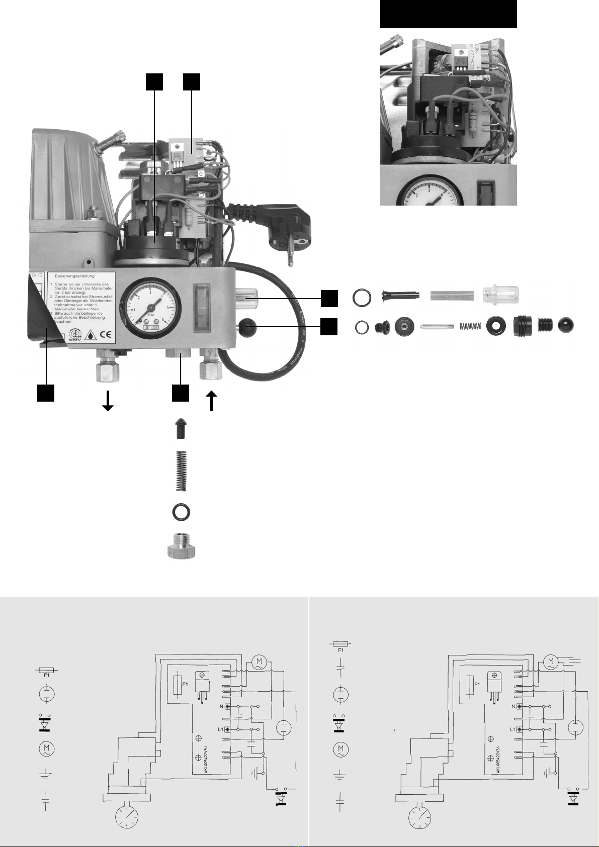
Test, over-pressure and
drain valve
The test, over-pressure and drain valve is the
cut-off point between the supply line and
suction line. When opened, it connects the
pressure and suction areas. No non-return
valve may therefore be installed in the
suction line. The over-pressure valve comes
into operation when the maximum set pres-
sure of 4 bar is exceeded. The proper
operation of the valve can be checked by
actuating it manually. It also enables the
pressure to be relieved in the complete
piping system and the storage vessel, and
the draining of the unit via the suction line.
Non-return valve
The non-return valve is fitted by means of
the plug screw. This prevents return flow or
loss of pressure in the oil already pumped
into the pressure storage vessel and the
supply line. To ventilate the unit, the plug
screw is removed complete with the non-
return valve.
Pressure switch
The pressure switch switches the motor on
at a lower working pressure of approx. 1.6
bar, and switches it off again on reaching the
upper working pressure of approx. 2.6 bar.
The pressure range can be regulated upward
in the case of supply heights of over 15 m.
This is done by screwing in the pressure set-
ting screw, using a small screwdriver or
small pin of max. 1.5 mm diameter in the
four slots of the pressure setting screw. The
safety cut-off must in this case be adjusted
to the lower working pressure of minus 0.1
bar. The pressure for the safety cut-off is
reduced by screwing the cross-head screw
in, and increased by screwing it out. In the
event of a drop in pressure to below the set
pressure as a result of a power failure, lack
of oil or break in the line, the safety cut-off
switches to “fault”, and the control lamp
lights up.
The installation, connection and testing of
heating oil supply systems must be carried
out in accordance with DIN 4755 Part 2. The
unit can be installed up to 1.5 m below the
upper tank level. The maximum suction head
of 3 m must not be exceeded. About 1.0 m
of suction head must be deducted for every
10 m of horizontal suction distance.
Example:
Calculating the suction head
Tank floor - unit = 1.5 m W1.5 m vertical
Horizontal = 2.0 m W0.2 m vertical
suction distance
Calculated suction head 1.7 m
The unit is mounted horizontally against the
wall. The unit is easy to adjust by means of
the movable assembly plates.
The leak detection system LS 1 (Art. No.
800.912) with collecting trough must be
mounted under the device.
If the pressure storage vessel is operated
with a double-walled safety tank or a GFK
tank, the pressure relief valve DV 1 (Art. No.
754.912) must be installed in conjunction
with leak detection system LS 1.
Suction line
The installation of a filter in the suction line is
not necessary, since a filter of adequate
capacity with a mesh size of 0.1 mm is already
built into the unit. The suction line should ter-
minate at least 5 cm above the tank floor.
No non-return valve may be
installed in the suction line.
The tank connection 041.912 for individual
tanks fulfils this requirement. In the case of
normal suction lines for plastic PE and PA
battery tanks, the rocker-lever non-return
valves must be replaced by rocker-lever
shut-off valves. In the case of OILPRESS
suction lines, rocker-lever shut-off valve can
be ordered under article no. 594.912.
Supply line
OILPRESS pressure storage units allow the
use of a single-line supply system (see
Piping diagram). The line can be laid in any
way required. Oil pressure regulators must
be installed so that the permissible pressure
range of the oil regulator of 125 mm – 3000
mm of oil is not exceeded at the combustion
point. The line from the oil pressure regulator
to the oil regulator should be laid at an
incline. When used for the supply of atomis-
ing burners, the user must check whether a
pressure regulator should also be installed.
178.822/07/15
The installation and maintenance instructions
are intended only for qualified technicians!
1. Open all valves in the system, including
the inlet valve at the oil regulator.
2. Insert the plug into the socket. The control
lamp will light up.
3. Unscrew the plug screw with the complete
non-return valve .
4. Press down the push button on the
underside of the unit until oil flows without
air bubbles.
5. Refit the plug screw with the complete
non-return valve .
6. Press down the push button until the
pointer of the manometer has reached the
green area (this may take up to 10 min.).
The unit then starts to operate automatical-
ly. On reaching the upper cut-off pressure
(approx. 2.6 bar), the unit switches off.
7. For testing purposes, the button of the
over-pressure valve is now slightly
withdrawn until the motor starts again.
Note the starting pressure, which should
be approx. 1.6 bar.
following lack of oil or power failure
Check whether the manometer is still
showing any pressure, and if so, press the
starter button until the motor continues to
run automatically. If the manometer shows
no pressure, restart as described under
“Starting and ventilation”.
The installation and electrical connection of
the unit, commissioning and maintenance,
must be carried out by a qualified technician.
In the event of maintenance work, and before
removing the cover hood, the unit must be
disconnected from the power supply by
removing the plug, and the pressure in the
pressure storage vessel must be relieved.
The operating instructions must be kept in
the vicinity of the system following installation.
An essential requirement for smooth opera-
tion of the pressure storage units is proper
installation in accordance with the technical
rules applicable to the planning, installation
and operation of the complete system.
The pressure storage units and the corre-
sponding pipes must be installed so that
they are protected against frost.
Heating oil is a material harmful to water.
Spilt or leaked heating oil must be disposed
of properly. All components which have
come into contact with heating oil must be
disposed of properly in accordance with
applicable disposal regulations.
This device is not intended for use by people
(incl. children) with restricted physical, sen-
sory or intellectual abilities or lack of expe-
rience and/or lack of knowledge, unless they
are supervised by a person responsible for
their saftey or received, from this person,
instructions about how to use the device.
Children should be supervised to ensure that
they do not play with the device.
If the device’s power cable is damaged it
must be replaced by the manufacturer or the
manufacturer’s customer service or a simi-
larly qualified specialist.
Pressure setting
screw
Cross-head screw
E
F
B
Installation Starting and ventilation
F
F
E
Restarting
Instructions
Maintenance work
Replacing the filter
In case of contamination and during mainte-
nance work, the filter should be replaced, in
order to ensure trouble-free operation.
D