Installation & Service Instructions
83-059-000
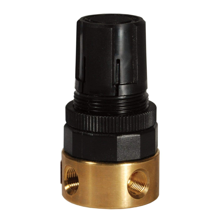
Regulator Model R16
With Variations and Accessories
ISSUED: April, 2006
Supersedes: September, 1995
Doc.# 83059000, ECN# 060135, Rev. 1
Richland, MI 49083 Tel: (269) 629-5000
WARNING
To avoid unpredictable system behavior that can cause personal injury
and property damage:
• Disconnect electrical supply (when necessary) before installation,
servicing, or conversion.
• Disconnect air supply and depressurize all air lines connected to
this product before installation, servicing, or conversion.
• Operate within the manufacturer’s specified pressure, temperature,
and other conditions listed in these instructions.
• Medium must be moisture-free if ambient temperature is below
freezing.
• Service according to procedures listed in these instructions.
• Installation, service, and conversion of these products must be
performed by knowledgeable personnel who understand how
pneumatic products are to be applied.
• After installation, servicing, or conversion, air and electrical supplies
(when necessary) should be connected and the product tested for
proper function and leakage. If audible leakage is present, or the
product does not operate properly, do not put into use.
• Warnings and specifications on the product should not be covered
by paint, etc. If masking is not possible, contact your local
representative for replacement labels.
!
!
WARNING
Product rupture can cause serious injury.
Do not connect regulator to bottled gas.
Do not exceed maximum primary pressure rating.
WARNING
FAILURE OR IMPROPER SELECTION OR IMPROPER USE OF THE
PRODUCTS AND/OR SYSTEMS DESCRIBED HEREIN OR RELATED ITEMS
CAN CAUSE DEATH, PERSONAL INJURY AND PROPERTY DAMAGE.
This document and other information from The Company, its subsidiaries
and authorized distributors provide product and/or system options for further
investigation by users having technical expertise. It is important that you
analyze all aspects of your application, including consequences of any
failure and review the information concerning the product or systems in the
current product catalog. Due to the variety of operating conditions and
applications for these products or systems, the user, through its own
analysis and testing, is solely responsible for making the final selection of
the products and systems and assuring that all performance, safety and
warning requirements of the application are met.
The products described herein, including without limitation, product features,
specifications, designs, availability and pricing, are subject to change by
The Company and its subsidiaries at any time without notice.
EXTRA COPIES OF THESE INSTRUCTIONS ARE AVAILABLE FOR
INCLUSION IN EQUIPMENT / MAINTENANCE MANUALS THAT UTILIZE
THESE PRODUCTS. CONTACT YOUR LOCAL REPRESENTATIVE.
!
REPAIR KITS AND REPLACEMENT PARTS
SELF-RELIEVING REPAIR KIT
(includes self-relieving diaphragm assembly,
valve assembly and o-rings) ........................................... RRP-95-130
NON-RELIEVING REPAIR KIT
(includes nonrelieving diaphragm assembly,
valve assembly and o-rings) ........................................... RRP-95-129
Self-Relieving Diaphragm Kit ............................................ RRP-96-213
Non-Relieving Diaphragm Kit ........................................... RRP-96-216
Valve Assembly (valve stem, valve spring) ...................... RRP-96-215
Regulating Springs:
0-50 psi ............................................................................ RRP-95-222
0-125 psi .......................................................................... GRP-95-224
0-250 psi .......................................................................... RRP-95-218
Adjusting Knob Assembly ................................................. RRP-95-023
ACCESSORIES
Gauges:
0-60 psig ....................................................................... K4520N14060
0-160 psig ..................................................................... K4520N14160
0-300 psig ..................................................................... K4520N14300
Panel Mount Nut ................................................................ GPA-95-032
Wall Mounting Bracket ...................................................... GPA-95-012
Wall Mounting with Panel Nut ........................................... GPA-95-011
Wall Mounting Bracket (Combo’s) .................................... RRP-95-090
Tamper Resistant Kit ......................................................... RRP-95-006
INSTALLATION
1. Install as close as possible to where regulated air is needed.
2. Install the unit with the air flowing in the direction indicated by the
arrow.
3. Install the same pipe size unit as the pipe line in use. Avoid using
fittings, couplings etc., that restrict airflow, unless maximum flow is
not needed.
4. Regulator may be installed with the adjusting knob in any position.
Attach gauge to one 1/4" female gauge port and plug the other 1/4"
female port or use it as a regulated outlet port.
5. Turning the adjusting screw clockwise increases the regulated
pressure and turning it counterclockwise decreases the regulated
pressure.
6. Panel mount regulators require a 15/16" diameter hole and are
mountable on panels from 1/8" to 1/2" thick.
7. Maximum inlet pressure and operating temperature ratings are
300 psig (21 bar) and 175°F (79°C).
MAINTENANCE
1. The regulator can be disassembled for servicing without removal
from line.
2. Occasionally remove bottom plug and clean plug, body and valve
seat (vent air line on both sides of regulator).
3. TO DISASSEMBLE - shut off air to regulator and vent air line on both
sides of regulator. Turn adjusting knob counterclockwise to relieve
compression on spring. Remove screw, lock knob, adjusting knob
(panel mount nut, if used), tamper-resistant kit (on tamper-resistant
models) and cover cap. Remove the four screws, cover and
regulating spring. Diaphragm assembly can now be removed. By
removing bottom plug and spring the valve stem can be removed
from the bottom of the regulator.
4. IF UNIT WILL NOT REGULATE TO PRESSURE NEEDED OR IF
PRESSURE BECOMES EXCESSIVE-remove bottom plug, spring,
and valve assembly. Clean and check o-ring, valve stem and valve
seat for water damaged parts. Install Repair Kit No. RRP-95-130 for
self-relieving models and Repair Kit RRP-95-129 for non-relieving
models for complete overhaul.
5. IF UNIT LEAKS AT RELIEF PORT, install proper repair kit as listed
under Repair Kits and Replacement Parts.
6. WHEN REPLACING DIAPHRAGM ASSEMBLY - Diaphragm
assembly RRP-96-213 includes disk seal (not shown) installed. Seal
not required on nonrelieving models.
7. TO REPLACE O-RING-This o-ring is above a metal washer which
cannot be removed. Using a pointed probe of some kind, pull o-ring
out. Force new o-ring through washer hole into o-ring cavity.

