MAINTENANCE INSTRUCTIONS
A. Field Adjustments – Following proper installation of the Wilkerson DE heatless air dryer, no
field adjustments are necessary. No lubrication is required on the dryer.
B. Six-Month Check – It is recommended that every 6 months of operation, unit be thoroughly
inspected. Inspection should include audible inspection of the towers switching and purge flow.
Visual inspection should include checking for excessive dirt or oil fouling and for desiccant
attrition at the outlet and purge exhaust area. Remove mufflers, if installed, and check for
excessive pressure drop by blowing through the muffler. If large resistance is felt, mufflers
should be replaced.
C. Purge Orifice – If the operating conditions change from the label specifications (eg. inlet pres-
sure, outlet flow), it is necessary to replace the purge orifice. There is one orifice in the DE3,
DE4 and DE5 air dryers. The orifice is an extremely critical part in determining the perfor-
mance of the dryer and no attempt should be made to enlarge or reduce the hole size. An ori-
fice of the proper size must be obtained from your local Wilkerson distributor. The label on the
dryer should also be changed, noting the present operating conditions. The purge orifice is
precision drilled in the outlet shuttle spool. To change the orifice, remove the three screws on
one side of the outlet shuttle valve. Remove and replace the orifice. Reassemble shuttle valve.
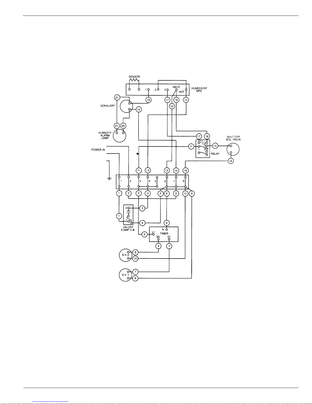
D. Cycle Timer – The solid state cycle timer requires no maintenance and can be replaced in
field.
E. Desiccant Towers – Desiccant towers are an all-welded design and are not repackable.
Replacement chambers should be obtained from your local Wilkerson distributor.
F. Operating Air Dryer Improperly – Following improper dryer operation, i.e., low inlet pressure,
high air temperature or high outlet flow, shut off the outlet flow from the air dryer for several
hours to allow the dryer to operate, purging the desiccant towers of excessive moisture. If this
does not restore dryer to proper working order, consult the troubleshooting guide.
G. Oil Contamination – Oil contamination of the desiccant towers will cause complete loss of
drying capability. If oil is detected in the desiccant towers or any other components, it will be
necessary to install replacement towers in order to restore dryer to normal operation. For this
reason, proper maintenance of the prefilters is essential.
H. Replacement Parts – Contact your local authorized Wilkerson distributor for dryers or replace-
ment parts.
IMPORTANT INFORMATION
The installation of parts not supplied by
Wilkerson will void the warranty of our air dryers.
For replacement part information, contact Wilkerson Applications Engineering, toll free at
1-888-223-5126.
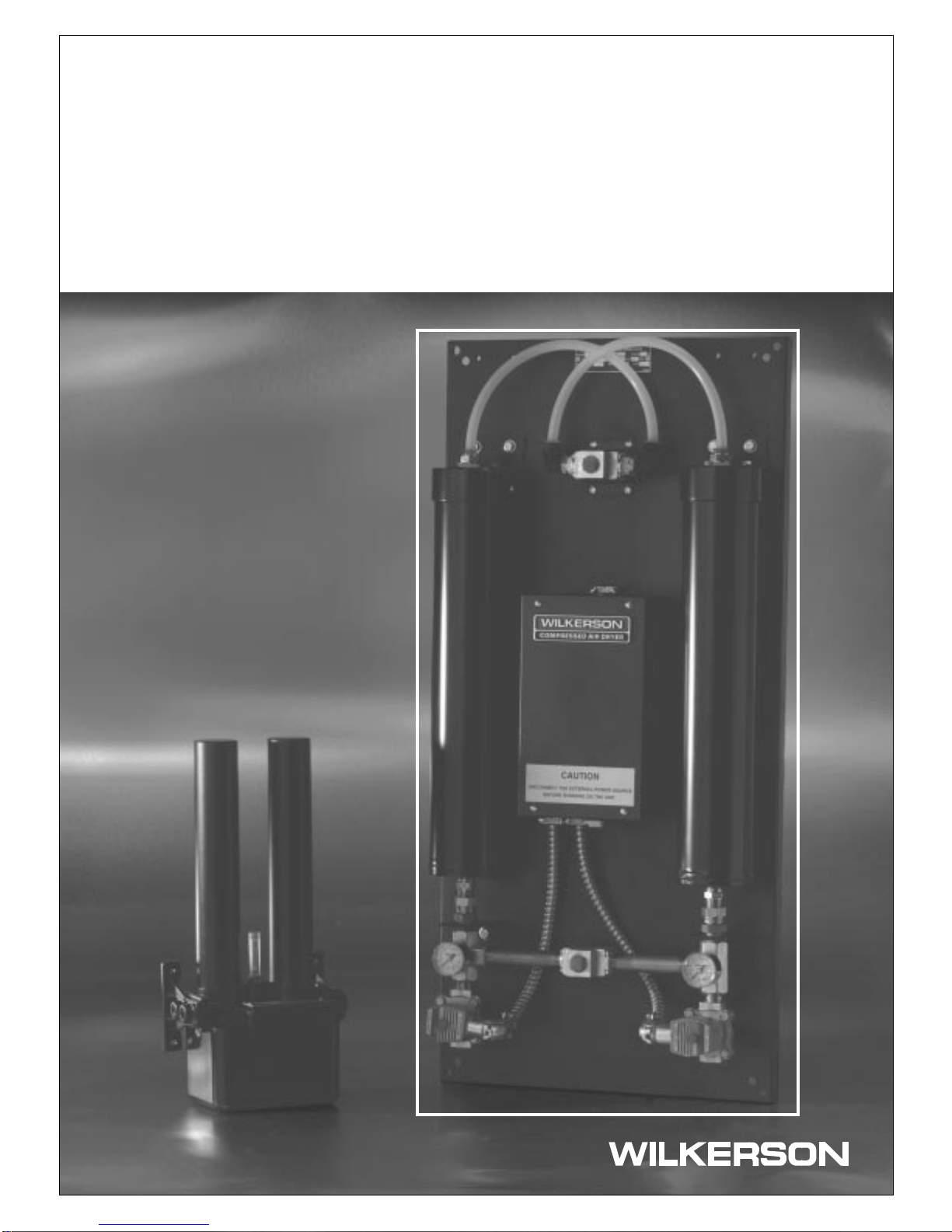
Instruction Manual / DE3, DE4 and DE5
Wilkerson Compact Heatless Air Dryers