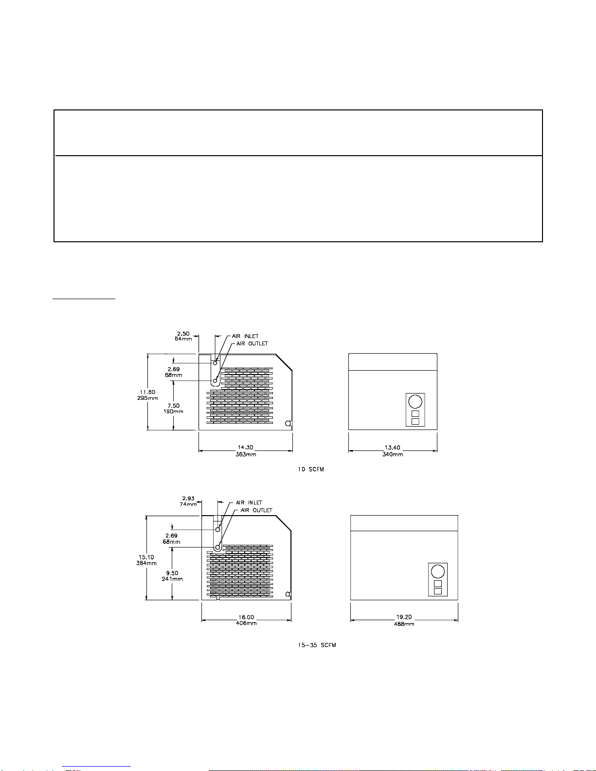
INSTALLATION
Air-Cooled Condenser (Standard)
The dryer should be installed in a well-ventilated area.
Ambient air should flow freely into the condenser
opening (right side of dryer). Do not block or restrict this
opening. There should be at least 12" (305 mm)
clearance at the back and both sides of the dryer. The
condenser fins and surfaces should be regularly
cleaned with an air blow gun. The grill can easily be re-
moved to access the condenser coil.
Ambient temperature should never be above 110°F
(43°C) or below 40°F (4.4°C).
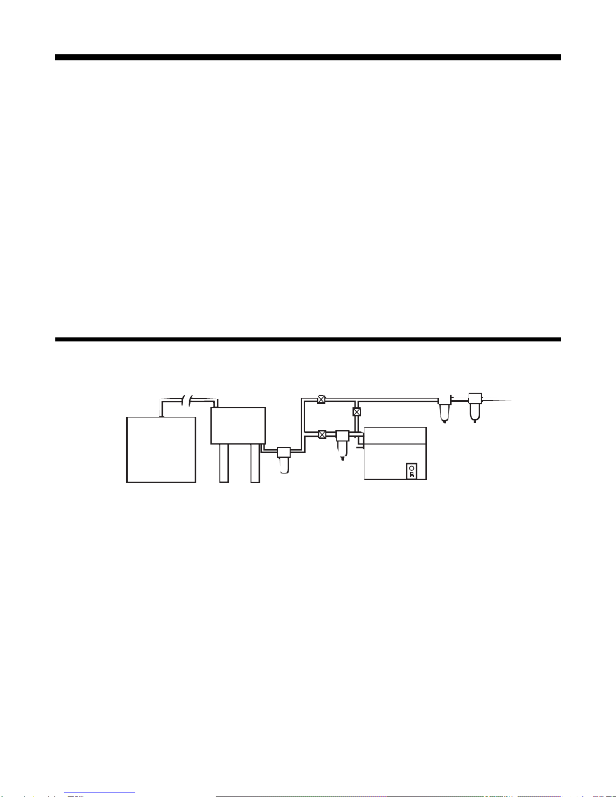
Compressed Air Piping
Pipe air “in” and “out” as indicated on dryer. Compressor
induced vibration (or any other vibration) should be
dampened by installing flexible piping between the dryer
and compressor, or vibration dampeners on dryer floor
legs. Prolonged vibration will damage dryer and void
warranty. If piping incorporates a bypass circuit
(recommended), make sure “in” and “out” shut-off
valves are normally wide open and bypass valve
completely closed. Do not undersize these valves.
Care Of Outside Of Dryer
This dryer is protected and decorated with the highest
quality paint for lasting attractive appearance. To clean
these surfaces, use a sponge, mild soap and warm
water. Dry with a clean cloth. Do not use any abra-
sives or solvents.
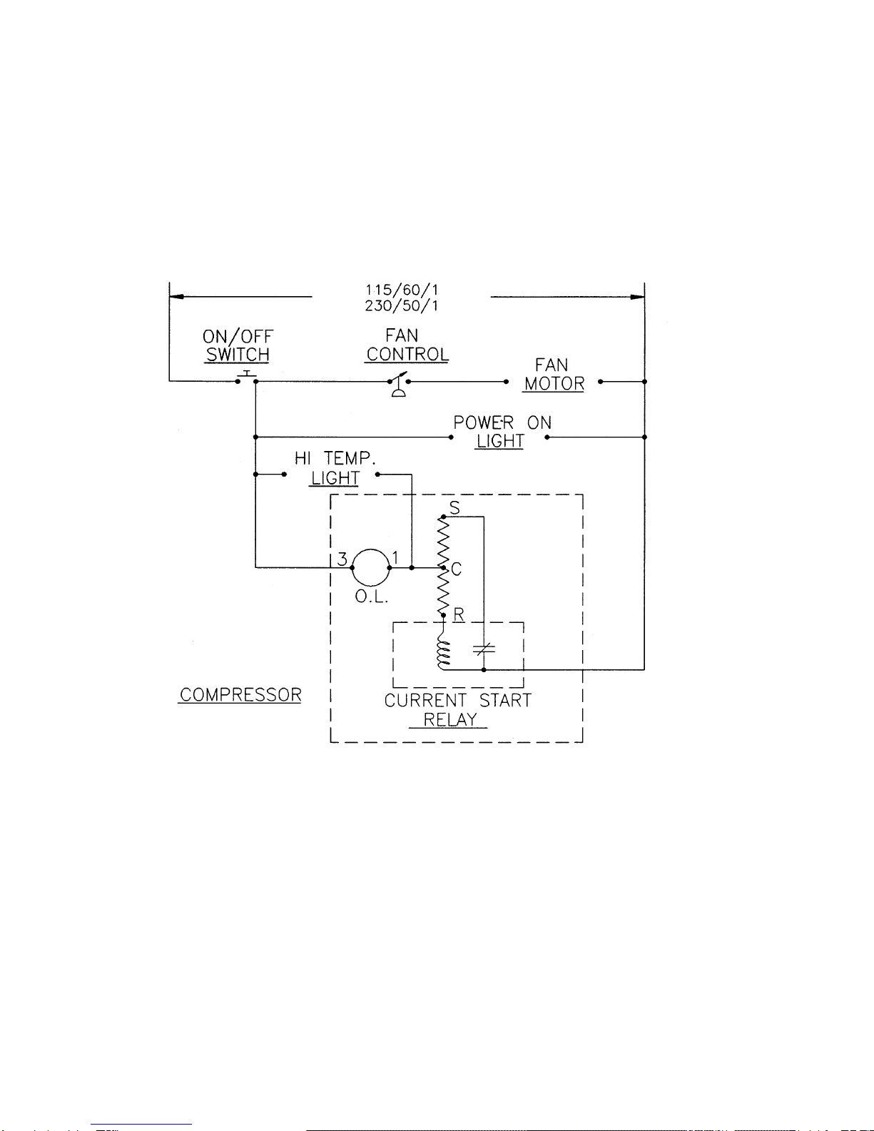
System Monitor
1. Dryer “Power on” on/off light illuminates to indicate
power is on to the dryer.
2. Optional Refrigerant Suction Gauge displays dryer
suction pressure.
3. High temperature warning light indicates the
compressor is not running.
Before Start-Up
The gauge readings BEFORE START UP will be:
1. REFRIGERANT SUCTION PRESSURE: Indicates the
refrigerant pressure and during shut down corresponds
with the ambient temperature (see page 5 for
temperature-pressure chart and convert ambient
temperature to pressure reading for R-22).
Example: 70° F ambient, R-22 pressure is approxi-
mately 121.4 psig.
Start-Up
DO NOT START WITH A LOAD ON THE DRYER
Bypass the flow of air around the dryer before pushing
the start button.
1. After pushing the start button, the power indicating
light will illuminate. Dryer is designed to run contin-
uously and must not be cycled with the air compressor.
The fan on air-cooled units will cycle in accordance with
head pressure.
2. The refrigerant suction pressure gauge readings
AFTER START UP AND WHILE OPERATING UNDER
RATED LOAD will be: R-22 (57-65 PSIG).
Page 4 WILKERSON